CN216386628U - Detection device convenient for detecting curvature of ball screw - Google Patents
Detection device convenient for detecting curvature of ball screw Download PDFInfo
- Publication number
- CN216386628U CN216386628U CN202122583193.6U CN202122583193U CN216386628U CN 216386628 U CN216386628 U CN 216386628U CN 202122583193 U CN202122583193 U CN 202122583193U CN 216386628 U CN216386628 U CN 216386628U
- Authority
- CN
- China
- Prior art keywords
- ball screw
- shaped head
- pressing mechanism
- machine tool
- head pressing
- Prior art date
- Legal status (The legal status is an assumption and is not a legal conclusion. Google has not performed a legal analysis and makes no representation as to the accuracy of the status listed.)
- Active
Links
- 238000001514 detection method Methods 0.000 title claims abstract description 18
- 230000007246 mechanism Effects 0.000 claims abstract description 57
- 208000010727 head pressing Diseases 0.000 claims description 34
- 238000005452 bending Methods 0.000 claims description 12
- 238000013016 damping Methods 0.000 claims description 7
- 230000006978 adaptation Effects 0.000 claims 1
- 238000000034 method Methods 0.000 abstract description 7
- 230000008569 process Effects 0.000 abstract description 7
- 230000008859 change Effects 0.000 description 4
- 238000005259 measurement Methods 0.000 description 4
- 230000009286 beneficial effect Effects 0.000 description 2
- 238000006073 displacement reaction Methods 0.000 description 2
- 230000036541 health Effects 0.000 description 2
- 230000005540 biological transmission Effects 0.000 description 1
- 238000012986 modification Methods 0.000 description 1
- 230000004048 modification Effects 0.000 description 1
Images


Landscapes
- A Measuring Device Byusing Mechanical Method (AREA)
Abstract
The utility model relates to the technical field of curvature detection, in particular to a detection device for conveniently detecting the curvature of a ball screw, and solves the problems that in the prior art, the ball screw needs to be detected by a curvature detection device and can only formally flow into the market after being qualified, in the conventional curvature detection process, personnel need to replace pressure heads with different shapes, such as U-shaped or V-shaped, the ball screw deforms and records data through repeated pressing, experimental data is obtained, a large number of ball screws are detected in a short time, the pressure heads need to be replaced manually and ceaselessly by the personnel, and the working efficiency cannot be improved. The utility model provides a conveniently detect detection device of ball screw crookedness, includes lathe, U-shaped head pushing down mechanism, V-arrangement head pushing down mechanism, and U-shaped head pushing down mechanism and V-arrangement head pushing down mechanism install respectively in the top both sides of lathe. The utility model saves the step of manually replacing the lower pressure head by personnel, improves the working efficiency and protects the body of the personnel at the same time.
Description
Technical Field
The utility model relates to the technical field of curvature detection, in particular to a detection device for conveniently detecting the curvature of a ball screw.
Background
The ball screw is an ideal product for converting rotary motion into linear motion or converting linear motion into rotary motion. The ball screw is the most commonly used transmission element on tool machinery and precision machinery, and has the main function of converting rotary motion into linear motion or converting torque into axial repeated acting force, and has the characteristics of high precision, reversibility and high efficiency.
However, ball need detect via crookedness detection device, just can formally flow into market after qualified, need personnel to change the pressure head of different shapes among the conventional crookedness testing process, like U-shaped or V-arrangement, make ball take place deformation and record data through the repeated pushing down, obtain experimental data, detect a large amount of ball in the short time and need personnel to change the pressure head incessantly manually, can't promote work efficiency, consequently need a detection device who conveniently detects ball crookedness.
SUMMERY OF THE UTILITY MODEL
The utility model aims to provide a detection device for conveniently detecting the curvature of a ball screw, and solves the problems that in the prior art, the ball screw needs to be detected by a curvature detection device and can only formally flow into the market after being qualified, in the conventional curvature detection process, personnel are required to replace pressure heads with different shapes, such as U-shaped or V-shaped, the ball screw is deformed and data is recorded through repeated pressing, experimental data is obtained, a large number of ball screws are detected in a short time, the pressure heads need to be replaced manually by the personnel without stopping, and the working efficiency cannot be improved.
In order to achieve the purpose, the utility model adopts the following technical scheme:
a detection device convenient for detecting the bending degree of a ball screw comprises a machine tool, a U-shaped head pressing mechanism and a V-shaped head pressing mechanism, wherein the U-shaped head pressing mechanism and the V-shaped head pressing mechanism are respectively arranged on two sides of the top of the machine tool, the four corners of the bottoms of the U-shaped head pressing mechanism and the V-shaped head pressing mechanism are fixedly connected with the top of the machine tool through telescopic rods, a measuring mechanism is arranged right below the U-shaped head pressing mechanism and positioned at the top of the machine tool, a sliding block is fixedly connected to the bottom of the measuring mechanism, a sliding plate is fixedly connected to one side of the sliding block, a sliding groove used for being in sliding connection with the sliding block is formed in the top of the machine tool, a moving groove communicated with the sliding groove and matched with the sliding plate is formed in one side of the machine tool, cylinders are fixedly connected to two sides of the outer wall of one side of the sliding plate, far away from the sliding block, and a connecting ring is sleeved on the outer rings of the cylinders, and the outer surface wall of the connecting ring is sleeved with a limiting rod, and one side of the machine tool close to the limiting rod is provided with a plurality of limiting grooves matched with one end of the limiting rod far away from the connecting ring.
Preferably, one end of the cylinder, which is far away from the sliding plate, is fixedly connected with a limiting wafer.
Preferably, four corners of the bottom of the machine tool are fixedly connected with anti-skid bases.
Preferably, one end of the limiting rod, which is close to the machine tool, is fixedly connected with a damping pad.
Preferably, a handle is arranged at the center of one side of the sliding plate far away from the sliding block.
Preferably, one side of the sliding plate, which is close to the limiting groove, penetrates through the moving groove, and the sliding plate is connected with the moving groove in a sliding manner.
The utility model has at least the following beneficial effects:
when the device is used by a person, the ball screw to be detected is placed on the upper surfaces of the two measuring mechanisms, the ball screw is stressed by the U-shaped head pressing mechanism to be bent and deformed, when the bending angle reaches a certain degree, the person detects whether the back surface of the concave part of the ball screw is broken or not, then the connecting ring of the outer ring of the moving cylinder drives the limiting rod to move, the sliding plate is pushed to drive the sliding block and the measuring mechanism on the sliding block to move to the position right below the V-shaped head pressing mechanism along the inner part of the sliding groove, the back of the concave part of the ball screw is pressed down by the V-shaped head pressing mechanism, so that the bent ball screw is reset, when a certain angle is reached, whether the pressed part is damaged or not is detected again, data are recorded, so that the measurement is completed, the step of manually replacing the pressing head by personnel is omitted, and the body of the personnel is protected while the working efficiency is improved.
The utility model also has the following beneficial effects:
through the setting of handle, make things convenient for the more convenient promotion slide of personnel for whole displacement process is smooth and easy more steadily, through the setting of spacing disk, has prevented that the go-between from droing from the cylindrical outer lane, through the setting of damping pad, has increased the compactness of being connected of gag lever post and spacing groove, through the setting of anti-skidding base, has increased device non-skid property.
Drawings
In order to more clearly illustrate the technical solutions of the embodiments of the present invention, the drawings needed to be used in the description of the embodiments are briefly introduced below, and it is obvious that the drawings in the following description are some embodiments of the present invention, and it is obvious for those skilled in the art to obtain other drawings based on these drawings without creative efforts.
FIG. 1 is a schematic view of the overall structure of the present invention;
FIG. 2 is a schematic view of the slider structure of the present invention;
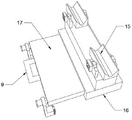
fig. 3 is a schematic structural view of a slide plate according to another embodiment of the present invention.
In the figure: 1. a machine tool; 2. a U-shaped head pressing mechanism; 3. a V-head hold-down mechanism; 4. a telescopic rod; 5. an anti-slip base; 6. a chute; 7. a moving groove; 8. a limiting groove; 9. a grip; 10. limiting the wafer; 11. a cylinder; 12. a connecting ring; 13. a limiting rod; 14. a damping pad; 15. a measuring mechanism; 16. a slider; 17. a slide board.
Detailed Description
In order to make the objects, technical solutions and advantages of the present invention more apparent, the present invention is described in further detail below with reference to the accompanying drawings and embodiments. It should be understood that the specific embodiments described herein are merely illustrative of the utility model and are not intended to limit the utility model.
Referring to fig. 1-3, a detection device for conveniently detecting the bending degree of a ball screw comprises a machine tool 1, a U-shaped head pressing mechanism 2 and a V-shaped head pressing mechanism 3, wherein the U-shaped head pressing mechanism 2 and the V-shaped head pressing mechanism 3 are respectively installed on two sides of the top of the machine tool 1, four corners of the bottoms of the U-shaped head pressing mechanism 2 and the V-shaped head pressing mechanism 3 are fixedly connected with the top of the machine tool 1 through telescopic rods 4, a measuring mechanism 15 is arranged right below the U-shaped head pressing mechanism 2 and on the top of the machine tool 1, a slide block 16 is fixedly connected with the bottom of the measuring mechanism 15, a slide plate 17 is fixedly connected with one side of the slide block 16, a chute 6 for slidably connecting with the slide block 16 is arranged on the top of the machine tool 1, a moving groove 7 communicated with the chute 6 and matched with the slide plate 17 is arranged on one side of the machine tool 1, a cylinder 11 is fixedly connected with two sides of the outer wall of one side of the slide plate 17 far away from the slide block 16, and the outer ring of the cylinder 11 is sleeved with a connecting ring 12, and the outer wall of the connecting ring 12 is sleeved with a limiting rod 13, one side of the machine tool 1 close to the limiting rod 13 is provided with a plurality of limiting grooves 8 matched with one ends of the limiting rods 13 far away from the connecting ring 12, concretely, when the machine tool is used by a person, the ball screw to be detected is placed on the upper surfaces of two measuring mechanisms 15, firstly, the ball screw is stressed by a U-shaped head pressing mechanism 2 to deform the ball screw, when the bending angle reaches a certain degree, the person detects whether the back surface of the concave part of the ball screw is broken, then the connecting ring 12 on the outer ring of the cylinder 11 is moved to drive the limiting rod 13 to move, so that one end of the limiting rod 13 is separated from the inside of the limiting groove 8, the slide plate 17 is pushed to drive the slide block 16 and the measuring mechanism 15 on the slide block 16 to move to the position right below the V-shaped head pressing mechanism 3 along the inside of the slide groove 6, the worker repositions the ball screw depression downward at the top of the measuring mechanism 15, presses down the back of the ball screw depression by the V-head pressing mechanism 3, so that the bent ball screw is reset, when the bent ball screw reaches a certain angle, whether the pressed part is damaged or not is detected again, and data is recorded, thus the measurement is completed, through the arrangement of the handle 9, the sliding plate 17 can be more conveniently pushed by personnel, so that the whole displacement process is smoother, the arrangement of the limiting wafer 10 prevents the connecting ring 12 from falling off from the outer ring of the column 11, the arrangement of the damping cushion 14 increases the connection tightness of the limiting rod 13 and the limiting groove 8, through the setting of antiskid base 5, increased device skid resistance, saved and needed personnel manual change pressure head down, protected staff's health when having promoted work efficiency.
The scheme has the following working processes:
when a person uses the device, the ball screw to be detected is placed on the upper surfaces of two measuring mechanisms 15, the ball screw is bent to deform through the stress of the U-shaped head pressing mechanism 2 on the ball screw, when the bending angle reaches a certain degree, the person detects whether the back surface of the concave part of the ball screw is broken or not, then the connecting ring 12 of the outer ring of the movable cylinder 11 drives the limiting rod 13 to displace, so that one end of the limiting rod 13 is separated from the inside of the limiting groove 8, the sliding plate 17 is pushed to drive the sliding block 16 and the measuring mechanism 15 on the sliding block 16 to move to the position under the V-shaped head pressing mechanism 3 along the inside of the sliding groove 6, the person places the concave part of the ball screw downwards on the top of the measuring mechanism 15 again, the back surface of the concave part of the ball screw is pressed through the V-shaped head pressing mechanism 3, so that the bent ball screw is reset, and when the ball screw reaches a certain angle, and detecting whether the pressed part is damaged or not again and recording data, so that the measurement is finished.
According to the working process, the following steps are known:
the step of manually replacing the lower pressure head by personnel is omitted, the working efficiency is improved, and meanwhile the body of the personnel is protected.
Further, one end of the cylinder 11, which is far away from the sliding plate 17, is fixedly connected with a limiting wafer 10, and specifically, the limiting wafer 10 is arranged to prevent the connecting ring 12 from falling off from the outer ring of the cylinder 11.
Further, the equal fixedly connected with skid resistant base 5 in four corners in bottom of lathe 1, it is concrete, through skid resistant base 5's setting, increased device skid resistance ability.
Further, one end of the limiting rod 13, which is close to the machine tool 1, is fixedly connected with a damping pad 14, and particularly, the connection tightness between the limiting rod 13 and the limiting groove 8 is increased through the arrangement of the damping pad 14.
Further, a grip 9 is installed at the center of one side of the sliding plate 17 far away from the sliding block 16, and particularly, through the arrangement of the grip 9, the sliding plate 17 can be pushed more conveniently by people.
Further, one side of the sliding plate 17, which is close to the limiting groove 8, penetrates through the moving groove 7, the sliding plate 17 is in sliding connection with the moving groove 7, and particularly, the position of the moving slide block 16 can be adjusted by a person from the outside conveniently through the arrangement of the sliding plate 17 and the moving groove 7.
In summary, the following steps: when a person uses the device, the ball screw to be detected is placed on the upper surfaces of two measuring mechanisms 15, the ball screw is stressed by a U-shaped head pressing mechanism 2 to be bent and deformed, when the bending angle reaches a certain degree, the person detects whether the back surface of the concave part of the ball screw is broken or not, then a connecting ring 12 of the outer ring of a movable cylinder 11 drives a limiting rod 13 to displace, so that one end of the limiting rod 13 is separated from the inside of a limiting groove 8, a sliding plate (17) is pushed to drive a sliding block 16 and a measuring mechanism 15 on the sliding block 16 to move to the position under a V-shaped head pressing mechanism 3 along the inside of a sliding groove 6, the person places the concave part of the ball screw downwards on the top of the measuring mechanism 15 again, the back surface of the concave part of the ball screw is pressed by the V-shaped head pressing mechanism 3, so that the bent ball screw is reset, when arriving certain angle, whether detect pressurized position again has damage and record data, so far, accomplished this measurement, saved the step that needs personnel's manual change to push down the pressure head, protected staff's health when having promoted work efficiency.
The foregoing shows and describes the general principles, essential features, and advantages of the utility model. It will be understood by those skilled in the art that the present invention is not limited to the embodiments described above, which are merely illustrative of the principles of the utility model, but that various changes and modifications may be made without departing from the spirit and scope of the utility model, which fall within the scope of the utility model as claimed. The scope of the utility model is defined by the appended claims and equivalents thereof.
Claims (6)
1. A detection device convenient for detecting the bending degree of a ball screw comprises a machine tool (1), a U-shaped head pressing mechanism (2) and a V-shaped head pressing mechanism (3), wherein the U-shaped head pressing mechanism (2) and the V-shaped head pressing mechanism (3) are respectively installed on two sides of the top of the machine tool (1), the detection device is characterized in that four corners of the bottoms of the U-shaped head pressing mechanism (2) and the V-shaped head pressing mechanism (3) are fixedly connected with the top of the machine tool (1) through telescopic rods (4), a measuring mechanism (15) is arranged right below the U-shaped head pressing mechanism (2) and positioned on the top of the machine tool (1), a sliding block (16) is fixedly connected to the bottom of the measuring mechanism (15), a sliding plate (17) is fixedly connected to one side of the sliding block (16), a sliding groove (6) used for being in sliding connection with the sliding block (16) is formed in the top of the machine tool (1), the utility model discloses a lathe, including lathe (1), spout (6) and slide (17), the equal fixedly connected with cylinder (11) in both sides of the outer wall of one side of slider (16) are kept away from in slide (17), and the outer lane cover of cylinder (11) is equipped with go-between (12) to the outer wall of go-between (12) has cup jointed gag lever post (13), lathe (1) is close to one side of gag lever post (13) and has seted up a plurality of and gag lever post (13) and keep away from spacing groove (8) of go-between (12) one end looks adaptation with gag lever post (13).
2. The device for detecting the bending degree of the ball screw conveniently according to the claim 1, characterized in that, a limiting disc (10) is fixedly connected with one end of the cylinder (11) far away from the sliding plate (17).
3. The device for detecting the bending degree of the ball screw conveniently according to claim 1, characterized in that anti-skid bases (5) are fixedly connected to four corners of the bottom of the machine tool (1).
4. The device for detecting the bending degree of the ball screw conveniently according to the claim 1, characterized in that a damping pad (14) is fixedly connected to one end of the limiting rod (13) close to the machine tool (1).
5. The device for detecting the bending degree of the ball screw conveniently according to the claim 1, characterized in that a handle (9) is installed at the center position of one side of the sliding plate (17) far away from the sliding block (16).
6. The device for detecting the bending degree of the ball screw conveniently according to the claim 1, characterized in that one side of the sliding plate (17) close to the limiting groove (8) penetrates through the moving groove (7), and the sliding plate (17) is connected with the moving groove (7) in a sliding way.
Priority Applications (1)
| Application Number | Priority Date | Filing Date | Title |
|---|---|---|---|
| CN202122583193.6U CN216386628U (en) | 2021-10-26 | 2021-10-26 | Detection device convenient for detecting curvature of ball screw |
Applications Claiming Priority (1)
| Application Number | Priority Date | Filing Date | Title |
|---|---|---|---|
| CN202122583193.6U CN216386628U (en) | 2021-10-26 | 2021-10-26 | Detection device convenient for detecting curvature of ball screw |
Publications (1)
| Publication Number | Publication Date |
|---|---|
| CN216386628U true CN216386628U (en) | 2022-04-26 |
Family
ID=81248006
Family Applications (1)
| Application Number | Title | Priority Date | Filing Date |
|---|---|---|---|
| CN202122583193.6U Active CN216386628U (en) | 2021-10-26 | 2021-10-26 | Detection device convenient for detecting curvature of ball screw |
Country Status (1)
| Country | Link |
|---|---|
| CN (1) | CN216386628U (en) |
Cited By (2)
| Publication number | Priority date | Publication date | Assignee | Title |
|---|---|---|---|---|
| CN116465319A (en) * | 2023-03-27 | 2023-07-21 | 深圳市三雅科技有限公司 | A ball screw gap measuring device |
| CN118583086A (en) * | 2024-07-31 | 2024-09-03 | 如东县丰利机械厂有限公司 | A barbell bar bending detection device |
-
2021
- 2021-10-26 CN CN202122583193.6U patent/CN216386628U/en active Active
Cited By (2)
| Publication number | Priority date | Publication date | Assignee | Title |
|---|---|---|---|---|
| CN116465319A (en) * | 2023-03-27 | 2023-07-21 | 深圳市三雅科技有限公司 | A ball screw gap measuring device |
| CN118583086A (en) * | 2024-07-31 | 2024-09-03 | 如东县丰利机械厂有限公司 | A barbell bar bending detection device |
Similar Documents
| Publication | Publication Date | Title |
|---|---|---|
| CN104493643B (en) | Online machining detection device and method for directional sleeve of overrun clutch | |
| CN101750208A (en) | Diaphragm spring tester | |
| CN219694802U (en) | Spring hardness detection device | |
| CN204381977U (en) | The machining on-line measuring device of the directed sleeve of a kind of freewheel clutch | |
| CN214952784U (en) | Grain hardness detection device | |
| CN210375051U (en) | Pressing structure of sheet metal part checking fixture | |
| CN212206013U (en) | Automatic length detection device for miniature shaft parts | |
| CN210119355U (en) | Plane closing device convenient to measure accuracy | |
| CN218062923U (en) | Hydraulic cylinder performance testing device | |
| CN213147675U (en) | Measuring device for circular angle of valve seat of engine cylinder cover valve | |
| CN214333600U (en) | Work piece protruding height detection tool | |
| CN217504756U (en) | Bearing roller ovality detection device | |
| CN215217398U (en) | Dial indicator calibrating device | |
| CN219747888U (en) | Valve pocket position measurement clamp | |
| CN216133100U (en) | Measuring jig convenient to clamping | |
| CN217237510U (en) | Sensor pressure testing device | |
| CN220508676U (en) | Oil cylinder push rod detection device | |
| CN222481810U (en) | A spring check fixture | |
| CN218628000U (en) | Gauge with anti-skid function | |
| CN221248543U (en) | Positioning mechanism for centering outside part | |
| CN219404076U (en) | Clamping mechanism for pressure weighing sensor | |
| CN222719355U (en) | Automobile piston hardness detection device | |
| CN221037254U (en) | Detection device for workpiece positioning | |
| CN215448744U (en) | Clamping type hardness detection device for steel structure round pipe | |
| CN218725993U (en) | Plastic goods resistance to compression check out test set |
Legal Events
| Date | Code | Title | Description |
|---|---|---|---|
| GR01 | Patent grant | ||
| GR01 | Patent grant |