Unloading mechanism in binary channels of battery electricity core
Technical Field
The utility model relates to the technical field of battery cells, in particular to a double-channel feeding and discharging mechanism of a battery cell.
Background
The battery cell is a raw material of a lithium ion polymer battery product, the battery cell is provided with pole ear parts, the pole ear parts are metal conductors leading positive and negative poles out of the battery cell, the ears of the positive and negative poles of the battery are in popular terms, one battery cell can extend out of the two pole ear parts, the pole ear parts are used as contact points of the battery during charging and discharging, and the pole ear parts comprise a plurality of pole ears.
In the production process of the lithium battery, whether the number of the tabs of the battery cell is correct and whether the tabs are folded are important factors directly related to the quality of the lithium battery product, so whether the number of the tabs of the battery cell is correct and whether the tabs are folded need to be detected.
In the tab detection process of the battery electric core, the conventional manual mode is usually adopted for feeding and discharging the battery electric core, so that the feeding and discharging efficiency is low, and the tab detection efficiency of the battery electric core is influenced.
SUMMERY OF THE UTILITY MODEL
Technical problem to be solved
Aiming at the defects of the prior art, the utility model provides a double-channel feeding and discharging mechanism of a battery cell, which can solve the technical problem.
(II) technical scheme
In order to solve the technical problems, the utility model provides the following technical scheme: the utility model provides a unloading mechanism on binary channels of battery electricity core, includes: the device comprises a support frame, two manipulator devices and two positioning cameras, wherein the two manipulator devices are arranged on one side of the support frame in the length direction, the two positioning cameras are respectively arranged close to two sides of the support frame in the width direction, and the shooting direction of the positioning cameras is vertical downwards; the manipulator device comprises a manipulator, a manipulator adjusting component and a pressing component, wherein the manipulator adjusting component comprises an x-axis adjusting component, a y-axis adjusting component, a z-axis adjusting component and a rotating component, the x-axis adjusting component is arranged on the support frame, the z-axis adjusting component is arranged on the x-axis adjusting component, the rotating component is arranged on the z-axis adjusting component, the y-axis adjusting component is arranged on the rotating component, and the manipulator and the pressing component are both arranged on the y-axis adjusting component.
Preferably, the fixed plates are arranged on two sides of the supporting frame in the width direction, and the positioning camera is arranged on the fixed plates.
Preferably, the x-axis adjusting assembly comprises a first motor, a first lead screw, a first adjusting plate and a first sliding block, the first adjusting plate is arranged on the support frame, the first adjusting plates of the two manipulator devices are adjacently arranged along the length direction of the support frame, the first adjusting plate is provided with a first sliding rail, the first sliding rail and the first lead screw are horizontally arranged along the length direction of the support frame, the first motor is arranged at one end of the first adjusting plate, the first motor is connected with the first lead screw, the first sliding block is arranged on the first sliding rail, and the first sliding block is in threaded connection with the first lead screw.
Preferably, the z-axis adjusting assembly comprises a second motor, a second lead screw, a second adjusting plate and a second slider, the second adjusting plate is provided with a second sliding rail, the second sliding rail and the second lead screw are vertically arranged, the second adjusting plate is fixedly connected with the first slider, the second motor is arranged at the top of the second adjusting plate and is connected with the second lead screw, the second slider is arranged on the second sliding rail, and the second slider is in threaded connection with the second lead screw.
Preferably, the rotating assembly comprises a third motor and a rotating disc, the third motor is arranged on the second sliding block, and the third motor is meshed with the rotating disc.
Preferably, the y-axis adjusting assembly comprises a third adjusting plate, a third sliding block, a fourth sliding block, a first air cylinder and a second air cylinder, the third adjusting plate is fixedly connected with the rotary table, the third adjusting plate is provided with a third sliding rail, the third sliding block and the fourth sliding block are arranged on the third sliding rail, the first air cylinder and the second air cylinder are arranged on the third adjusting plate, the third sliding block is connected with the first air cylinder, and the fourth sliding block is connected with the second air cylinder.
Preferably, the manipulator includes first backup pad and second backup pad, and first backup pad sets up with the second backup pad relatively, first backup pad and third slider fixed connection, second backup pad and fourth slider fixed connection.
Preferably, the pressing assembly comprises a third cylinder, a fourth cylinder, a first pressing plate and a second pressing plate, the top of the first pressing plate is connected with the third cylinder, the top of the second pressing plate is connected with the fourth cylinder, the first pressing plate is arranged close to the first supporting plate, the second pressing plate is arranged close to the second supporting plate, the third cylinder is fixedly connected with the third sliding block, and the fourth cylinder is fixedly connected with the fourth sliding block.
(III) advantageous effects
Compared with the prior art, the utility model provides a double-channel loading and unloading mechanism of a battery cell, which has the following beneficial effects: the battery cell is grabbed through the manipulator, the compaction assembly ensures the grabbing firmness, and the manipulator adjusting assembly can realize the left-right, up-down, front-back direction adjustment and rotation adjustment of the manipulator; in addition, the vision positioning of the feeding and discharging position is realized by arranging the positioning camera.
Drawings
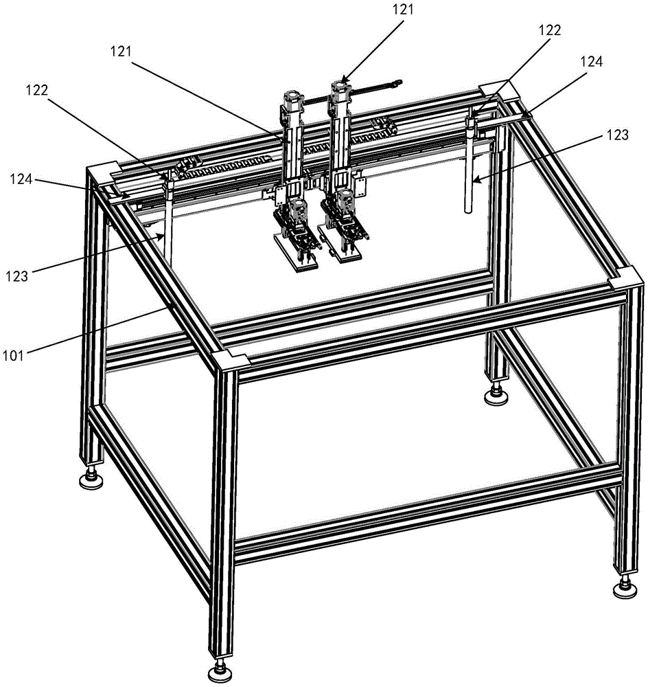
Fig. 1 is a schematic perspective view of a dual-channel loading and unloading mechanism of a battery cell according to the present invention;
fig. 2 is a first partial structural schematic diagram of a dual-channel loading and unloading mechanism of a battery cell according to the present invention;
fig. 3 is a second partial structural schematic diagram of the dual-channel loading and unloading mechanism of the battery electric core according to the utility model;
fig. 4 is a third partial structural schematic diagram of the dual-channel loading and unloading mechanism of the battery electric core according to the present invention;
fig. 5 is a fourth partial structural schematic diagram of the dual-channel loading and unloading mechanism of the battery cell.
The reference numbers in the figures are: 101 support frame, 102 first motor, 103 first regulating plate, 104 first slider, 105 second motor, 106 second regulating plate, 107 second slider, 108 third motor, 109 third regulating plate, 110 third slider, 111 fourth slider, 112 first support plate, 113 second support plate, 114 third cylinder, 115 fourth cylinder, 116 first press plate, 117 second press plate, 118 battery cell, 119 first cylinder, 120 second cylinder, 121 manipulator device, 122 positioning camera, 123 positioning camera shooting direction, 124 fixing plate.
Detailed Description
The technical solutions in the embodiments of the present invention will be clearly and completely described below with reference to the drawings in the embodiments of the present invention, and it is obvious that the described embodiments are only a part of the embodiments of the present invention, and not all of the embodiments. All other embodiments, which can be derived by a person skilled in the art from the embodiments given herein without making any creative effort, shall fall within the protection scope of the present invention.
The utility model relates to a double-channel loading and unloading mechanism of a battery cell, which comprises: the two positioning cameras 122 are respectively arranged close to two sides of the width direction of the support frame 101, and the shooting direction 123 of the positioning cameras is vertical downwards.
The manipulator device 121 comprises a manipulator, a manipulator adjusting assembly and a pressing assembly, the manipulator adjusting assembly comprises an x-axis adjusting assembly, a y-axis adjusting assembly, a z-axis adjusting assembly and a rotating assembly, the x-axis adjusting assembly is arranged on the support frame 101, the z-axis adjusting assembly is arranged on the x-axis adjusting assembly, the rotating assembly is arranged on the z-axis adjusting assembly, the y-axis adjusting assembly is arranged on the rotating assembly, and the manipulator and the pressing assembly are arranged on the y-axis adjusting assembly.
It should be understood that the manipulator is used for grabbing the battery cell 118, the pressing assembly is used for pressing the battery cell 118, the x-axis adjusting assembly is used for adjusting the position of the manipulator in the left-right direction of the x-axis, the y-axis adjusting assembly is used for adjusting the position of the manipulator in the front-back direction of the y-axis, the z-axis adjusting assembly is used for adjusting the position of the manipulator in the up-down direction of the z-axis, and the rotating assembly is used for controlling the rotation of the y-axis adjusting assembly. After the manipulator is adjusted to a proper position by the manipulator adjusting assembly, the manipulator grabs the battery cell 118, and further moves the battery cell 118 to a loading position for detection or blanking by the manipulator adjusting assembly; it should be understood that detection stations of the battery cells 118 are arranged on two sides of the support frame 101 in the width direction, so as to realize double-channel loading or unloading corresponding to the operations of the two manipulator devices 121; in addition, the positioning camera 122 is configured to perform shooting positioning on the battery electric core 118 to determine whether the battery electric core 118 is in place, so as to implement visual positioning on a loading and unloading position.
Compared with the prior art, the utility model provides a double-channel loading and unloading mechanism of a battery cell, which has the following beneficial effects: the battery cell is grabbed through the manipulator, the compaction assembly ensures the grabbing firmness, and the manipulator adjusting assembly can realize the left-right, up-down, front-back direction adjustment and rotation adjustment of the manipulator; in addition, the vision positioning of the feeding and discharging position is realized by arranging the positioning camera.
In this embodiment, the fixing plates 124 are disposed on both sides of the supporting frame 101 in the width direction, and the positioning camera 122 is disposed on the fixing plates 124; other structures may be provided in other embodiments to achieve fixation of the positioning camera 122, without limitation.
It is to be understood that the two robot devices 121 have the same structure, and the structure of the robot device 121 will be described in detail below.
In this embodiment, the x-axis adjusting assembly specifically includes a first motor 102, a first lead screw, a first adjusting plate 103, and a first slider 104. The first adjusting plate 103 is arranged on the support frame 101, the first adjusting plates 103 of the two manipulator devices 121 are arranged adjacently along the length direction of the support frame 101, the first adjusting plates 103 are provided with first slide rails, the first slide rails and first lead screws are horizontally arranged along the length direction of the support frame 101, the first motor 102 is arranged at one end of the first adjusting plates 103, the first motor 102 is connected with the first lead screws, the first sliding blocks 104 are arranged on the first slide rails, and the first sliding blocks 104 are in threaded connection with the first lead screws. It can be understood that the first motor 102 drives the first lead screw to rotate, so as to drive the first slider 104 to slide left and right on the first slide rail. Of course, in other embodiments, the x-axis adjustment assembly may be provided in other configurations, and is not limited herein.
In this embodiment, the z-axis adjusting assembly includes a second motor 105, a second lead screw, a second adjusting plate 106, and a second slider 107. The second adjusting plate 106 is provided with a second slide rail, the second slide rail and the second lead screw are both vertically arranged, the second adjusting plate 106 is fixedly connected with the first slider 104, the second motor 105 is arranged at the top of the second adjusting plate 106, the second motor 105 is connected with the second lead screw, the second slider 107 is arranged on the second slide rail, and the second slider 107 is in threaded connection with the second lead screw. It can be understood that the first slide block 104 can drive the z-axis adjusting assembly to move left and right integrally; the second motor 105 drives the second lead screw to rotate, so as to drive the second slide block 107 to slide up and down on the second slide rail.
In the present embodiment, the rotating unit includes a third motor 108 and a turntable. The third motor 108 is disposed on the second slider 107, and the third motor 108 is engaged with the turntable. It can be understood that the second slider 107 can drive the rotating assembly to move up and down integrally; the third motor 108 may drive the turntable to rotate.
In the present embodiment, the y-axis adjusting assembly includes a third adjusting plate 109, a third slider 110, a fourth slider 111, a first cylinder 119, and a second cylinder 120. The third adjusting plate 109 is fixedly connected with the turntable, the third adjusting plate 109 is provided with a third slide rail, the third slider 110 and the fourth slider 111 are both arranged on the third slide rail, the first air cylinder 119 and the second air cylinder 120 are both arranged on the third adjusting plate 109, the third slider 110 is connected with the first air cylinder 119, and the fourth slider 111 is connected with the second air cylinder 120. It can be understood that the rotating component can drive the y-axis adjusting component to integrally rotate; the first air cylinder 119 drives the third slider 110 to slide back and forth on the third slide rail, and the second air cylinder 120 drives the fourth slider 111 to slide back and forth on the third slide rail.
In this embodiment, the manipulator includes a first support plate 112 and a second support plate 113, the first support plate 112 and the second support plate 113 are disposed opposite to each other, the first support plate 112 and the third slider 110 are fixedly connected, and the second support plate 113 and the fourth slider 111 are fixedly connected. The pressing assembly comprises a third air cylinder 114, a fourth air cylinder 115, a first pressing plate 116 and a second pressing plate 117, the top of the first pressing plate 116 is connected with the third air cylinder 114, the top of the second pressing plate 117 is connected with the fourth air cylinder 115, the first pressing plate 116 is arranged close to the first supporting plate 112, the second pressing plate 117 is arranged close to the second supporting plate 113, the third air cylinder 114 is fixedly connected with the third sliding block 110, and the fourth air cylinder 115 is fixedly connected with the fourth sliding block 111. It is understood that the third slider 110 can move the first support plate 112, the first cylinder 114 and the first press plate 116 back and forth on the third slide rail, and the fourth slider 111 can move the second support plate 113, the second cylinder 115 and the second press plate 117 back and forth on the third slide rail. The first pressing plate 116 and the second pressing plate 117 are used for supporting the battery cell 118, the third air cylinder 114 is used for controlling the first pressing plate 116 to ascend and descend so as to compress the battery cell 118, and the fourth air cylinder 115 is used for controlling the second pressing plate 117 to ascend and descend so as to compress the battery cell 118.
Of course, in other embodiments, the number of the slide blocks of the y-axis adjusting assembly can be one, and the manipulator can be connected with the single slide block by adopting a single gripper structure correspondingly.
It is to be noted that the terms "comprises," "comprising," or any other variation thereof, are intended to cover a non-exclusive inclusion, such that a process, method, article, or apparatus that comprises a list of elements does not include only those elements but may include other elements not expressly listed or inherent to such process, method, article, or apparatus. Without further limitation, an element defined by the phrase "comprising an … …" does not exclude the presence of other identical elements in a process, method, article, or apparatus that comprises the element.
Although embodiments of the present invention have been shown and described, it will be appreciated by those skilled in the art that changes, modifications, substitutions and alterations can be made in these embodiments without departing from the principles and spirit of the utility model, the scope of which is defined in the appended claims and their equivalents.