CN216373496U - Inner lining paper processing and boxing equipment - Google Patents
Inner lining paper processing and boxing equipment Download PDFInfo
- Publication number
- CN216373496U CN216373496U CN202122977230.1U CN202122977230U CN216373496U CN 216373496 U CN216373496 U CN 216373496U CN 202122977230 U CN202122977230 U CN 202122977230U CN 216373496 U CN216373496 U CN 216373496U
- Authority
- CN
- China
- Prior art keywords
- lining paper
- adsorption
- station
- die
- paper
- Prior art date
- Legal status (The legal status is an assumption and is not a legal conclusion. Google has not performed a legal analysis and makes no representation as to the accuracy of the status listed.)
- Active
Links
- 238000012545 processing Methods 0.000 title claims abstract description 25
- 238000004806 packaging method and process Methods 0.000 claims abstract description 24
- 238000004026 adhesive bonding Methods 0.000 claims abstract description 16
- 230000007246 mechanism Effects 0.000 claims description 96
- 238000001179 sorption measurement Methods 0.000 claims description 66
- 230000007306 turnover Effects 0.000 claims description 41
- 238000012856 packing Methods 0.000 claims description 39
- 230000033001 locomotion Effects 0.000 claims description 8
- 238000005096 rolling process Methods 0.000 claims description 6
- 230000003044 adaptive effect Effects 0.000 claims description 2
- 238000013459 approach Methods 0.000 claims description 2
- 238000004519 manufacturing process Methods 0.000 abstract description 8
- 230000000670 limiting effect Effects 0.000 description 15
- 238000013461 design Methods 0.000 description 13
- 238000010521 absorption reaction Methods 0.000 description 12
- 230000000694 effects Effects 0.000 description 10
- 229920000297 Rayon Polymers 0.000 description 9
- 238000009957 hemming Methods 0.000 description 9
- 239000000463 material Substances 0.000 description 8
- 238000003825 pressing Methods 0.000 description 8
- 238000000034 method Methods 0.000 description 5
- 238000010586 diagram Methods 0.000 description 4
- 239000003292 glue Substances 0.000 description 4
- 238000009434 installation Methods 0.000 description 4
- 230000008569 process Effects 0.000 description 4
- 239000000853 adhesive Substances 0.000 description 2
- 230000001070 adhesive effect Effects 0.000 description 2
- 238000005452 bending Methods 0.000 description 2
- 230000002093 peripheral effect Effects 0.000 description 2
- 241000252254 Catostomidae Species 0.000 description 1
- 206010066054 Dysmorphism Diseases 0.000 description 1
- 230000009471 action Effects 0.000 description 1
- 230000006978 adaptation Effects 0.000 description 1
- 239000002390 adhesive tape Substances 0.000 description 1
- 230000000712 assembly Effects 0.000 description 1
- 238000000429 assembly Methods 0.000 description 1
- 238000010009 beating Methods 0.000 description 1
- 230000009286 beneficial effect Effects 0.000 description 1
- 230000005540 biological transmission Effects 0.000 description 1
- 230000003139 buffering effect Effects 0.000 description 1
- 230000008859 change Effects 0.000 description 1
- 235000019504 cigarettes Nutrition 0.000 description 1
- 239000002131 composite material Substances 0.000 description 1
- 230000006835 compression Effects 0.000 description 1
- 238000007906 compression Methods 0.000 description 1
- 230000008094 contradictory effect Effects 0.000 description 1
- 238000013016 damping Methods 0.000 description 1
- 230000007547 defect Effects 0.000 description 1
- 238000010030 laminating Methods 0.000 description 1
- 239000012528 membrane Substances 0.000 description 1
- 238000012986 modification Methods 0.000 description 1
- 230000004048 modification Effects 0.000 description 1
- 230000001737 promoting effect Effects 0.000 description 1
- 238000007493 shaping process Methods 0.000 description 1
- 238000012546 transfer Methods 0.000 description 1
Images





Landscapes
- Making Paper Articles (AREA)
Abstract
The utility model discloses a lining paper processing and boxing device, which comprises: the gluing station is used for receiving the inner lining paper with the A surface facing upwards and the B surface facing downwards and gluing the A surface of the inner lining paper; the overturning station is used for sucking the lining paper from the surface A of the lining paper and overturning the lining paper to enable the surface B to face upwards and the surface A to face downwards; the edge folding station is used for adsorbing and fixing the lining paper from the surface B of the lining paper and folding the lining paper; and the boxing station is used for loading the lining paper into the packaging box. According to the utility model, by changing the sequence of the folding edge and the gluing, the inner lining paper can be glued in a planar state and then folded, so that the existing planar gluing equipment can be used, and automatic production and assembly can be realized.
Description
Technical Field
The utility model relates to the technical field of packaging box processing, in particular to lining paper processing and packaging equipment.
Background
Some products, such as cigarette, white spirit, etc. can lay interior slip sheet in the packing carton for increase protection and aesthetic property, and in order to guarantee interior slip sheet and the laminating degree of packing carton and adhere to firm nature, will generally fold interior slip sheet into the shape with packing carton adaptation and glue on interior slip sheet, then paste in the packing carton.
To the processing demand that this kind of needs are attached in the box, current producer is solved like this: set up an artifical station and fold the shaping back in advance with interior slip sheet specially, pile up and regard as the prepareeing material in accomodating the basket, then take one in another artifical station with the single centre form of interior slip sheet matching, cover interior slip sheet in the peripheral week side rubberizing of interior slip sheet again, then put into the opening box with centre form and interior slip sheet together, close the lid and extrude the gluing fastness to the four lateral walls of packing carton, open the lid at last, take out the centre form in the interior slip sheet.
The inventor aims at the production requirement to adopt a new process route to realize automatic assembly so as to replace a manual assembly line, so the inventor urgently needs to develop a new lining paper processing and boxing device to solve the technical problems.
SUMMERY OF THE UTILITY MODEL
The utility model mainly aims to provide lining paper processing and boxing equipment, and aims to solve the technical problem of replacing the existing manual assembly line.
In order to achieve the purpose, the utility model provides lining paper processing and boxing equipment, which comprises:
the gluing station is used for receiving the inner lining paper with the A surface facing upwards and the B surface facing downwards and gluing the A surface of the inner lining paper;
the overturning station is used for sucking the lining paper from the surface A of the lining paper and overturning the lining paper to enable the surface B to face upwards and the surface A to face downwards;
the edge folding station is used for adsorbing and fixing the lining paper from the surface B of the lining paper and folding the lining paper;
and the boxing station is used for loading the lining paper into the packaging box.
Further, be equipped with on the upset station:
the turnover mechanism is used for sucking the lining paper from the surface A of the lining paper and driving the lining paper to turn over towards the bearing mechanism by facing the surface A of the lining paper to the bearing mechanism;
and the bearing mechanism is used for enabling the A surface positioned on the turnover mechanism to receive the lining paper after the turnover mechanism drives the lining paper to turn over, and driving the lining paper to move.
Further, the receiving mechanism comprises a receiving bracket, a receiving table movably arranged on the receiving bracket and a movement driving component for driving the receiving table to move on the receiving bracket, and the turnover mechanism receives the lining paper by the receiving table.
Furthermore, offer on the accepting table and be used for letting to be located the protection of interior slip sheet on viscose groove of stepping down after receiving interior slip sheet.
Further, be provided with on the hem station:
the mould mechanism comprises an adsorption mould and is used for fixing the inner lining paper;
the edge folding mechanism comprises at least one narrow-edge roller and is used for extruding the lining paper to bend due to incomplete rolling contact with the lining paper;
the positioning mechanism and/or the edge folding mechanism is/are provided with a driving mechanism which is used for driving the corresponding adsorption mould or the narrow-edge roller to move so as to enable the adsorption mould and the narrow-edge roller to approach and separate from each other.
Furthermore, the number of the narrow-edge rollers is more than two and the narrow-edge rollers are distributed at intervals.
Further, be provided with on the dress box station:
the opening positioning mechanism is used for keeping the packing box in an open state;
the combined die is used for carrying the lining paper to be filled into the packaging box and comprises an adsorption die I, an adsorption die II and a splicing and withdrawing moving mechanism, the splicing and withdrawing moving mechanism can drive the adsorption die II to move to the whole body which is spliced with the adsorption die I to form the inner lining paper adaptive to the adsorption die II before assembly, and the adsorption die II is driven to move out the inner lining paper from the opening of the inner lining paper before the adsorption die I is assembled.
Further, the opening positioning mechanism includes:
the conveyor can form limit fit with the lower cover of the packing box and is used for conveying the packing box;
the first gag lever post and the second gag lever post that the interval set up, the upper cover slip card of packing carton is established between first gag lever post and second gag lever post for carry on spacingly to the upper cover of packing carton.
Furthermore, the whole formed by splicing the first adsorption mould and the second adsorption mould is cuboid.
Further, an included angle between the side surface and the bottom surface of the first adsorption mold and/or the second adsorption mold is smaller than 90 degrees.
The utility model has the beneficial effects that:
according to the utility model, by changing the sequence of the folding edge and the gluing, the inner lining paper can be glued in a planar state and then folded, so that the existing planar gluing equipment can be used, and automatic production and assembly can be realized.
Drawings
FIG. 1 is a layout diagram of stations of a liner paper boxing apparatus according to an embodiment of the present invention;
FIG. 2 is a flow chart of the packing apparatus for lining paper processing according to an embodiment of the present invention;
FIG. 3 is a schematic structural diagram of an apparatus at a flipping station according to an embodiment of the present disclosure;
FIG. 4 is a schematic structural diagram of a receiving mechanism according to an embodiment of the present invention;
FIG. 5 is a schematic view of the flip arm and the receiving platform in accordance with an embodiment of the present invention;
FIG. 6 is a schematic view of the apparatus at the hemming station according to an embodiment of the present invention;
FIG. 7 is a side view of the structure of FIG. 6 (with the mounting bracket omitted);
FIG. 8 is a schematic perspective view of a folding mechanism according to an embodiment of the present invention;
FIG. 9 is a schematic side view of the structure of FIG. 8;
FIG. 10 is a schematic structural view of a mold mechanism according to an embodiment of the present invention;
FIG. 11 is a schematic view of an apparatus at a boxing station in one embodiment of the present invention;
FIG. 12 is a schematic view of a position relationship between a stop lever and a packing box according to an embodiment of the present invention;
FIG. 13 is a schematic perspective view of a mold assembly according to an embodiment of the present invention;
FIG. 14 is a side view of the structure of FIG. 13;
FIG. 15 is a schematic structural diagram of a supporting mechanism according to an embodiment of the present invention;
FIG. 16 is a flow chart illustrating operation of the boxing station in one embodiment of the present invention.
Description of reference numerals:
01 gluing station, 02 turning station, 03 flanging station, 04 boxing station, 05 feeding station and 06 turntable;
10 turnover mechanisms, 101 turnover supports, 102 turnover arms, 103 turnover driving parts and 104 adsorption parts;
20 bearing mechanisms, 201 bearing brackets, 202 bearing tables, 203 moving driving parts, 204 linear drivers, 205 clappers, 2021 turnover mechanism abdicating grooves, 2022 clapping abdicating grooves, 2023 anti-touch abdicating grooves, 2024 ribs and 2025 air suction holes;
30 of a die mechanism, an adsorption die 301, a support assembly 302, a vertical moving module 3021 and a horizontal moving module 3022;
40 edge folding mechanisms, 401 narrow-edge rollers, 402 supporting parts, 403 driving parts, 404 rollers, 405 bases, 406 elastic parts, 407 supports, 408 supporting shafts and 409 mounting frames;
the device comprises a 50-opening positioning mechanism, a 501 conveyor, a 502 first limiting rod and a 503 second limiting rod;
the assembling die comprises a 60 assembling die, a 601 adsorption die I, a 602 adsorption die II, a 603 splicing and retreating moving module, a 604 assembling and moving module, a 605 retreating moving module, a 606 additional adsorption die, a 607 supporting and pressing component, a 6011 movable abdicating notch, a 6071 push rod, a 6072 supporting and pressing driver and a 6073 bracket;
100 lining paper, 1001 glue and 200 packaging boxes.
Detailed Description
The technical solutions in the embodiments of the present invention will be clearly and completely described below with reference to the drawings in the embodiments of the present invention, and it is obvious that the described embodiments are only a part of the embodiments of the present invention, and not all of the embodiments. The embodiments and features of the embodiments in the present application may be combined with each other without conflict. All other embodiments, which can be derived by a person skilled in the art from the embodiments given herein without making any creative effort, shall fall within the protection scope of the present invention.
It should be noted that, if directional indications (such as up, down, left, right, front, and back … …) are involved in the embodiment of the present invention, the directional indications are only used to explain the relative positional relationship between the components, the movement situation, and the like in a specific posture (as shown in the drawing), and if the specific posture is changed, the directional indications are changed accordingly.
In addition, if there is a description of "first", "second", etc. in an embodiment of the present invention, the description of "first", "second", etc. is for descriptive purposes only and is not to be construed as indicating or implying relative importance or implicitly indicating the number of technical features indicated. Thus, a feature defined as "first" or "second" may explicitly or implicitly include at least one such feature. In addition, the meaning of "and/or" appearing throughout includes three juxtapositions, exemplified by "A and/or B" including either A or B or both A and B. In addition, "a plurality" means two or more. In addition, technical solutions between various embodiments can be combined with each other, but must be realized by a person skilled in the art, and when the technical solutions are contradictory or cannot be realized, the combination of the technical solutions should be considered to be nonexistent.
Referring to fig. 1 to 16, the inner liner paper processing and boxing apparatus of the present invention includes:
the gluing station 01 is used for receiving the inner lining paper 100 with the A surface facing upwards and the B surface facing downwards and gluing the A surface of the inner lining paper 100;
an inverting station 02 for sucking the inner liner paper 100 from the a-side of the inner liner paper 100 and inverting the inner liner paper 100 into a B-side up and a-side down;
a folding station 03 for fixing the lining paper 100 by suction from the side B of the lining paper 100 and folding the lining paper 100;
and a boxing station 04 for loading the lining paper 100 into the packing box 200.
Generally speaking, it is easier to operate to glue on the stock when the stock is in the plane state than being in the viscose on the stock under the three-dimensional state, and prior art selects the processing mode of viscose after the hem, and the interior slip sheet after the hem is three-dimensional shape, and is high to viscose equipment requirement, and equipment cost is high, consequently, is forced to select artifical rubberizing.
According to the utility model, by changing the sequence of the folding edge and the gluing, the inner lining paper can be glued in a planar state, and then the glued inner lining paper is folded, so that the automatic production and assembly can be realized by using the existing planar gluing equipment, such as a rolling brush, or a double-faced adhesive tape tearing device (application No. 2020216938677) previously applied by the applicant.
In the utility model, the lining paper comprises two meanings, namely the lining paper before forming, namely the lining paper supplied material without the folded edge, and the lining paper after forming, namely the formed lining paper with the folded edge, for the sake of brevity, the utility model is not described in a distinguishing way, the lining paper is uniformly described, and the meanings of the lining paper can be understood by a person skilled in the art according to the station where the lining paper is located.
The transfer of interior slip sheet can adopt the conveyer belt, and in the concrete implementation, can also set up interior slip sheet material loading station 05 before viscose station 01 for place interior slip sheet on the conveyer belt one by one, the material loading station can use artifical material loading, also can use current paper material loading attachment, does not do the special restriction.
Referring to fig. 3 to 5:
in an embodiment, the turning station 02 is provided with:
a turnover mechanism 10 configured to suck the lining paper 100 from the a surface of the lining paper 100, and drive the lining paper 100 to turn over toward the receiving mechanism 20 with the a surface of the lining paper 100 facing the receiving mechanism 20;
and the receiving mechanism 20 is configured to receive the lining paper 100 on the a surface of the lining paper 100 by the turnover mechanism 10 after the turnover mechanism 10 drives the lining paper 100 to turn over, and drive the lining paper 100 to move.
The inner lining paper is pasted in the packaging box, in the pasting process, one surface of the inner lining paper facing the packaging box is the surface A, and the surface of the inner lining paper facing away from the packaging box is the surface B. In order to ensure the liner paper is firmly attached, the surface A of the liner paper is generally partially glued.
The existing operation flow is that firstly, the A surface of the lining paper faces upwards, the B surface faces downwards, then, the A surface of the lining paper is glued, then, the B surface of the lining paper is adsorbed by the turnover device to drive the lining paper to turn over to the B surface faces upwards, the A surface faces downwards, finally, the turnover device is moved to send the lining paper to the next station, and the lining paper is subsequently pasted in the packaging box. The defect of this method is that the adhesive is adhered to the side A of the inner lining paper, the inner lining paper needs to be sucked from the side B during the adhering process, so that the side A of the inner lining paper can be conveniently adhered in the packing box, and the turnover device is positioned on the side B of the inner lining paper after the turnover device is turned over to cause blockage, so that the turnover device needs to be moved away to suck the inner lining paper from the side B, and the working hours are increased.
This application distinguishes prior art, slip sheet upset in not absorbing from the B face of slip sheet, but absorb the material upset from the A face of slip sheet, after the upset, tilting mechanism and supporting mechanism give way each other, the A face that can not interfere the slip sheet contacts with supporting mechanism, thereby the slip sheet can its A face place on supporting mechanism, and thus, after the upset, the A face side of slip sheet including tilting mechanism still, can not cause and block, the B face side of slip sheet exposes completely, slip sheet in the equipment of next station can directly absorbing from the B face, the action has been reduced, work efficiency obtains promoting.
In one embodiment, the flipping mechanism 10 includes a flipping bracket 101, a flipping arm 102 mounted on the flipping bracket 101, a flipping driving part 103 for driving the flipping arm 102 to flip, and an adsorption part 104 mounted on the flipping arm 102. Adsorption element is used for absorbing interior slip sheet, can select adsorption equipment such as sucking disc, and the upset arm is used for supporting and drives adsorption element, and the optional rotation is installed on the upset support, and upset drive division is used for driving the reciprocal upset of upset arm, and the rotary motor can be chooseed for use to the upset drive division, and the rotary motor (not shown) output shaft is connected with the upset arm.
The turnover angle of the turnover mechanism is designed according to actual needs, and the turnover mechanism can be designed to turn 180 degrees in a horizontal plane in a general production process. When the turnover mechanism absorbs the lining paper from the surface A of the lining paper, the turnover mechanism needs to avoid a viscose or other contact-proof areas, in order to realize the function, the adsorption part can be arranged to be composed of a plurality of small suckers, or other modes such as abdicating space are arranged, and no special limitation is made.
In one embodiment, the receiving mechanism 20 includes a receiving frame 201, a receiving platform 202 movably disposed on the receiving frame 201, and a movement driving part 203 for driving the receiving platform 202 to move on the receiving frame 201, and the turnover mechanism 10 receives the liner paper 100 with the receiving platform 202. After the lining paper is turned over, the surface A of the lining paper is placed on the bearing table, and the movable driving part drives the bearing table to convey the lining paper to the next station.
During specific implementation, the bearing table can be slidably mounted on the bearing support through components such as a sliding rail or a sliding rod, the moving driving part can select linear drivers such as an air cylinder, an oil cylinder and a linear motor, no special limitation is needed, and a damping structure can be arranged for improving stability.
In an embodiment, the receiving platform 202 is provided with a turnover mechanism receding groove 2021 for allowing the turnover mechanism 10 to recede after the turnover mechanism 10 drives the inner lining paper 100 to turn over. The turnover mechanism stretches into the turnover mechanism yielding groove after turnover, so that yielding is realized, interference with the bearing table is prevented, and the surface A of the lining paper is ensured to be placed on the bearing table.
Preferably, the tilting arm 102 is designed in an L-shape. The design is convenient for configure into the slip direction perpendicular to the upset direction of upset arm of bearing platform to change the production line trend, make spatial layout more reasonable.
In one embodiment, the receiving mechanism 20 further comprises at least one patting arrangement structure for patting the lining paper 100 from the side of the lining paper 100. Pat arrangement structure and be used for lining paper to arrange in order and align.
In an embodiment, two of the flapping arrangements are disposed, the two flapping arrangements are disposed on two sides perpendicular to each other, and the other two sides of the receiving platform 202 opposite to the two flapping arrangements are disposed with protruding ribs 2024 for limiting the inner lining paper. Design like this, it is spacing to follow the internal slip sheet of four sides to beat the arrangement from both sides, can align the lining paper arrangement, ensure the processing accuracy.
In one embodiment, the clapping arrangement comprises a linear drive 204 and a clapper 205 connected to the linear drive 204. The clapper is used for beating interior slip sheet from the side, and linear actuator is used for driving the clapper flexible, and linear actuator can select drive devices such as cylinder, hydro-cylinder, linear motor for use, and the mountable is not do the special restriction on bearing platform or other peripheral equipment.
In an embodiment, the receiving platform 202 has at least one flapping way groove 2022, and the flap plate 205 of the flapping arrangement structure is located in the flapping way groove 2022. To slip sheet in some dysmorphism, the side is whole or the part does not expose the platform that holds, sets up to beat and gives the groove and supply to clap the board activity, can realize the arrangement of clapping to 100 sides of slip sheet.
In an embodiment, the a surface of the lining paper 100 has a contact-proof area, and the receiving platform 202 has a contact-proof groove 2023 for receiving the lining paper 100 and then allowing the lining paper to be located in the contact-proof area. The design is mainly aimed at the design that the surface A of the inner lining paper is provided with viscose glue and the like which can not be touched, and the design of the anti-touch abdicating groove is used for avoiding the touch of the bearing table.
In an embodiment, the receiving platform 202 is provided with an air suction hole 2025 for generating a vacuum absorption effect. By the design, the bearing table has an adsorption effect and can more firmly fix the lining paper.
Referring to fig. 6 to 10:
in an embodiment, the hemming station 03 is provided with:
a mold mechanism 30 including an adsorption mold 301 for fixing the liner paper 100;
the edge folding mechanism 40 comprises at least one narrow-edge roller 401 and is used for forming incomplete rolling contact with the lining paper 100 so as to press the lining paper 100 to be folded;
the die mechanism 30 and/or the hemming mechanism 40 are provided with a driving mechanism for driving the corresponding suction die 301 or the narrow-edge roller 401 to move, so that the suction die 301 and the narrow-edge roller 401 move close to and away from each other.
The main problem of the inner lining paper edge folding is that the viscose (indicated by 1001 filling area in the figure) on the inner lining paper can adhere to the edge folding mechanism to cause poor edge folding effect or damage the viscose.
The size of the edge width of the narrow-edge roller can be selected according to actual conditions, so that the narrow-edge roller can roll over the lining paper in a manner of reducing adhesion as far as possible without special limitation, the narrow-edge roller can be in a disc shape, a spherical shape or a spindle shape shown in the attached drawings, and a circle of narrow edges in rolling contact with the lining paper can be provided without special limitation.
In one embodiment, the number of the narrow-side rollers 401 is more than two and the narrow-side rollers are spaced from each other. By the design, the edge can be folded uniformly from multiple points, for example, three edges are shown in the attached drawings, the edges can be bent from two sides and the middle, and the edge folding effect is better.
In one embodiment, the hemming mechanism further includes at least one roller 404 having a diameter smaller than the narrow-side roller 401 and disposed coaxially with the narrow-side roller 401. The cylinder can be used for separating apart the narrow limit gyro wheel on the one hand, and on the other hand also can carry out the hem to interior slip sheet, and cylinder and narrow limit gyro wheel can mutual independence set up, also can integrated into one piece set up.
The adsorption mould is used for adsorbing fixed interior slip sheet on the one hand, and on the other hand as forming die, inject the hem shape of interior slip sheet, for example when needing to fold interior slip sheet into rectangle box-like, the adsorption mould sets up to the cuboid.
Some interior slip sheets need many hem, can set up a plurality of hem mechanisms as required, and the limit that some interior slip sheets need to be rolled over even carries out the secondary hem, and the relative direction of motion of corresponding hem mechanism and mould mechanism can be adjusted to this kind of condition.
The driving mechanism is not particularly limited as long as the narrow-edge roller can roll through the lining paper along the bending direction, whether the driving mechanism is arranged on the die mechanism, the edge folding mechanism or both.
For example, in an embodiment, the mold mechanism 30 includes a support assembly 302, the suction mold 301 is mounted on the support assembly 302, and the support assembly 302 includes a vertical moving module 3021 and a horizontal moving module 3022 for driving the suction mold 301 to move vertically and horizontally, respectively. For another example, in an embodiment, the hemming mechanism 40 includes a supporting member 402, the narrow-side roller 401 is slidably disposed on the supporting member 402, and the hemming mechanism 40 further includes a driving member 403 for driving the narrow-side roller to slide on the supporting member 402.
The vertical moving module, the transverse moving module and the driving part can be linear drivers such as an air cylinder, an oil cylinder, a linear motor and the like, and are not particularly limited. Preferably select for use the slip table cylinder, be convenient for realize the slidable mounting of corresponding component.
In one embodiment, the hemming mechanism 40 further includes an elastic buffer structure, and the narrow-side roller 401 is disposed on the elastic buffer structure. When processing, can realize the elastic contact of hem gyro wheel and absorption mould through elastic buffer structure, prevent to cross just easily folding, damage equipment.
In one embodiment, the hemming mechanism 40 further includes a base 405, the base 405 is slidably mounted on the supporting member 101, the driving member 403 is connected to the base 405, the buffering structure includes a support 407 slidably disposed on the base 405 and an elastic member 406 connected between the base 405 and the support 407, and the narrow-side roller 401 is disposed on the support 407. The elastic component has outside elasticity to the support, can guarantee that roller components in close contact with adsorbs the mould and roll lining paper 100, simultaneously, again can the adaptability compress and avoid roller components and adsorption mould collision, the elastic component can select for use the spring.
In one embodiment, the support 407 has a support shaft 408 mounted thereon, and the narrow-side roller 401 and the drum 404 are mounted on the support shaft 408. The design has simple structure and easy implementation, and the rolling installation of the roller and the roller can be realized as long as at least one part between the support shaft and the support and between the narrow-edge roller and the support shaft is in running fit.
In one embodiment, to facilitate installation, a mounting bracket 409 is provided, and the hemming mechanism 40 is mounted on the mounting bracket 409 or on the ground.
Referring to fig. 11 to 16:
in an embodiment, the boxing station 04 is provided with:
an opening positioning mechanism 50 for keeping the packing box 200 in an open state;
the assembling die 60 is used for loading the lining paper 100 into the packaging box 200 and comprises a first adsorption die 601, a second adsorption die 602 and a splicing and withdrawing die set 603, wherein the splicing and withdrawing die set 603 can drive the second adsorption die 602 to move to be spliced with the first adsorption die 601 to form a whole matched with the lining paper 100 before assembly, and drive the second adsorption die 602 to remove the lining paper 100 from the opening of the lining paper 100 before the first adsorption die 601 is assembled.
The new process route has a difficult problem to be solved: after the lining paper is packed into the box, the hand can ingeniously keep away the shielding part of the opening of the lining paper with the inner mold (the formed lining paper is generally matched with the packing box, the opening is also arranged at the position of the opening of the corresponding packing box and used for filling products into the inner mold, and when the shielding part exists in the opening of the lining paper, the size of the formed opening is smaller than that of the mold), so that the mold is taken out.
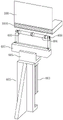
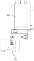
According to the utility model, manual assembly can be replaced by matching of the two adsorption moulds, before the inner lining paper and the packaging box are assembled, the adsorption mould II is driven to move to be integrally spliced with the adsorption mould I through the splicing and retreating moving mould group, the inner lining paper is adsorbed and fixed on the assembling mould, then the assembling mould carries the inner lining paper to be loaded into the packaging box, the adsorption mould II is completely exposed to the opening of the inner lining paper, after the inner lining paper and the packaging box are assembled, the adsorption mould II is firstly moved out of the inner lining paper from the opening of the inner lining paper through the splicing and retreating moving mould group, then the adsorption mould I is moved towards the original position of the adsorption mould II, so that the adsorption mould I is completely exposed to the opening of the inner lining paper, and finally the adsorption mould is withdrawn from the inner lining paper once the opening of the inner lining paper, so that the condition that the shielding part of the inner lining paper is avoided and the assembling mould is taken out.
In one embodiment, an additional suction mold 606 is installed on the top of the first suction mold 601, the second suction mold 602 is slidably installed on the additional suction mold 606, and the splicing and retracting movement mold 603 is installed on the additional suction mold 606. The additional adsorption mould is used for adsorbing the part of the fixed inner lining paper, which exceeds the packaging box, so that the assembly stability is improved, the adsorption mould II and the adsorption mould I are integrated together, and the driving combined mould is convenient to integrally assemble and demould.
In one embodiment, the packaging machine further comprises an assembling moving module 604 for driving the first absorption mold 601 and the second absorption mold 602 to be loaded into the packaging box and reset to the initial position.
In one embodiment, the mold stripping module 605 is further included for moving the first suction mold 601 to a position aligned with the opening of the liner paper and returning to the initial position after assembly.
For the convenience of processing, accord with general production law, can set up the composite mold and last, the packing carton is under, and both assemble and the demolding in vertical direction, and under this condition, the assembly removes the module and configures into vertical movement, and the demolding removes the module and configures into lateral shifting, and during the assembly, can be as illustrated, additional absorption mould removes the module with the assembly and is connected, and the assembly removes the module and removes the module with the demolding and be connected.
In an embodiment, the whole body formed by splicing the first absorption mold 601 and the second absorption mold 602 is rectangular. The packing box and the lining paper are generally rectangular parallelepiped, and the shape of the combined die can be designed to be matched with the rectangular parallelepiped packing box and the lining paper.
In one embodiment, the pressing component 607 is disposed on the first suction mold 601 and/or the second suction mold 602, and is used for pressing the inner lining paper toward the inner wall of the packing box after assembly, so that the inner lining paper and the packing box are more fit. Preferably, the compression assemblies 607 are disposed at the adhesive locations of the respective inner liner papers 100. By the design, the lining paper can be adhered to the inner wall of the packing box more firmly.
In one embodiment, the pressing component 607 includes a push rod 6071 slidably disposed in the first suction mold 601 and/or the second suction mold 602 toward the packing box 200 and a pressing driver 6072 for driving the push rod 6071 to slide, and the push rod 6071 can extend and retract the first suction mold 601 and/or the second suction mold 602 under the driving of the pressing driver 6072. The push rod stretches out to be capable of extruding lining paper to be attached to the packaging box, the push rod retracts to not influence the demolding of the combined die, and the combined die is simple in design structure, easy to implement and convenient to operate.
In an embodiment, prop and press subassembly 607 still includes support 6073, prop and press the driver 6072 and install on the additional absorption mould 606, support 6073 with prop and press the driver 6072 and connect, it is corresponding on absorption mould one 601 and or the absorption mould two 602 the position department of push rod 6071 opens there is the activity breach of stepping down 6011, support 6073 stretches into in the activity breach of stepping down 6011 with push rod 6071 with be connected. The supporting and pressing driver is in transmission with the push rod through the support, so that the structure is more reasonable, and the requirements on installation space and position are small.
In an embodiment, an included angle between a side surface and a bottom surface of the first adsorption mold 601 and/or the second adsorption mold 602 is less than 90 degrees. Design like this, the drawing of patterns of being convenient for on the one hand, on the other hand, the absorption mould I can regard as the hem mould with the absorption mould II is whole, during the hem, can make the face of bending bend and exceed 90 degrees to improve the hem effect.
The assembly moving mechanism, the moving mechanism that moves back, piece together move the module, prop and press the driver and can choose for use linear drive modules such as cylinder, hydro-cylinder, linear electric motor, do not do the special restriction, preferred slip table cylinder that uses can be when providing the driven, be convenient for realize the slidable mounting of corresponding part, the practicality is better.
In one embodiment, the opening positioning mechanism 50 includes: the conveyor 501 can be in limit fit with the lower cover of the packaging box 200 and is used for conveying the packaging box 200; the first limiting rod 502 and the second limiting rod 503 are arranged at intervals, and the upper cover of the packaging box 200 is slidably clamped between the first limiting rod 502 and the second limiting rod 503 and used for limiting the upper cover of the packaging box 200.
In fig. 11, the position relationship between the upper cover of the packing box and the two limiting rods is not completely shown, and particularly, referring to fig. 12, in the present invention, the lower cover of the packing box can be limited from rebounding towards the upper cover by the limiting fit between the conveyor and the lower cover of the packing box; the upper cover of the packing box can be limited to rebound towards the lower cover through the limiting action of the two limiting rods of the limiting assembly on the upper cover of the packing box, so that the packing box is ensured to be in an open state; and two gag lever posts and the upper cover sliding fit of packing carton, the conveyer can carry the packing carton and carry out the back-and-forth movement, is convenient for shift on the production line at the packing carton.
In one embodiment, the conveyor 501 is a conveying belt, and the conveying belt is provided with a limiting groove matched with the lower cover of the packing box 200. The design is simple in structure and reliable in positioning effect.
In the concrete implementation, the die mechanism 30 on the hem station 03 and the combined die 60 on the boxing station 04 can be the same set of die, and it moves and uses as die mechanism on the hem station, moves and uses as the combined die on the boxing station, and the design need not trade the membrane midway, can save operating time. The adsorption mould is a component capable of generating negative pressure to form a vacuum adsorption effect, is similar to a sucker, is commonly designed in a hollow mode at present, and is provided with a structure with an air suction hole on an adsorption surface.
For the structure illustrated in the figure, the suction mold 301 is formed by combining the first suction mold 601 and the second suction mold 602, and the assembling moving module 604 and the demolding moving module 605 are the vertical moving module 3021 and the horizontal moving module 3022.
Preferably, the utility model also provides a turntable 06, and the die mechanism 30, namely the combined die 60, is arranged on the turntable 06, so that the turntable can carry the dies to sequentially move to the bearing mechanism, the edge folding station and the boxing station, which is convenient and fast, and the length of the equipment can be shortened, the material trend can be changed, and the rationality of the installation space of the equipment can be improved by arranging the turntable.
The above description is only for the purpose of illustrating the preferred embodiments of the present invention and is not to be construed as limiting the utility model, and any modifications, equivalents, improvements and the like that fall within the spirit and principle of the present invention are intended to be included therein.
Claims (10)
1. The utility model provides an interior slip sheet processing cartoning equipment which characterized in that includes:
the gluing station is used for receiving the inner lining paper with the A surface facing upwards and the B surface facing downwards and gluing the A surface of the inner lining paper;
the overturning station is used for sucking the lining paper from the surface A of the lining paper and overturning the lining paper to enable the surface B to face upwards and the surface A to face downwards;
the edge folding station is used for adsorbing and fixing the lining paper from the surface B of the lining paper and folding the lining paper;
and the boxing station is used for loading the lining paper into the packaging box.
2. The lining paper processing and boxing apparatus as claimed in claim 1, wherein the turning station is provided with:
the turnover mechanism is used for sucking the lining paper from the surface A of the lining paper and driving the lining paper to turn over towards the bearing mechanism by facing the surface A of the lining paper to the bearing mechanism;
and the bearing mechanism is used for enabling the A surface positioned on the turnover mechanism to receive the lining paper after the turnover mechanism drives the lining paper to turn over, and driving the lining paper to move.
3. The liner paper processing and cartridge loading apparatus according to claim 2, wherein the receiving mechanism includes a receiving bracket, a receiving table movably provided on the receiving bracket, and a movement driving means for driving the receiving table to move on the receiving bracket, and the turnover mechanism receives the liner paper with the receiving table.
4. The lining paper processing and boxing apparatus as claimed in claim 3, wherein the receiving table is provided with a contact preventing groove for allowing the lining paper to be glued after receiving the lining paper.
5. The lining paper processing and boxing apparatus as claimed in claim 1, wherein the folding station is provided with:
the mould mechanism comprises an adsorption mould and is used for fixing the inner lining paper;
the edge folding mechanism comprises at least one narrow-edge roller and is used for extruding the lining paper to bend due to incomplete rolling contact with the lining paper;
the die mechanism and/or the edge folding mechanism is/are provided with a driving mechanism for driving the corresponding adsorption die or the narrow-edge roller to move so as to enable the adsorption die and the narrow-edge roller to approach and separate from each other.
6. The linerboard processing and cartoning apparatus of claim 5 wherein the number of the narrow side rollers is more than two and spaced apart from each other.
7. The lining paper processing and boxing apparatus as claimed in claim 1, wherein the boxing station is provided with:
the opening positioning mechanism is used for keeping the packing box in an open state;
the combined die is used for carrying the lining paper to be filled into the packaging box and comprises an adsorption die I, an adsorption die II and a splicing and withdrawing moving mechanism, the splicing and withdrawing moving mechanism can drive the adsorption die II to move to the whole body which is spliced with the adsorption die I to form the inner lining paper adaptive to the adsorption die II before assembly, and the adsorption die II is driven to move out the inner lining paper from the opening of the inner lining paper before the adsorption die I is assembled.
8. The liner paper processing and cartoning apparatus of claim 7, wherein the opening positioning mechanism comprises:
the conveyor can form limit fit with the lower cover of the packing box and is used for conveying the packing box;
the first gag lever post and the second gag lever post that the interval set up, the upper cover slip card of packing carton is established between first gag lever post and second gag lever post for carry on spacingly to the upper cover of packing carton.
9. The lining paper processing and boxing apparatus as claimed in claim 7, wherein the first adsorption mold and the second adsorption mold are spliced to form a whole body in a rectangular parallelepiped shape.
10. The lining paper processing and boxing apparatus as claimed in claim 7, wherein an included angle between the side surface and the bottom surface of the first adsorption mold and/or the second adsorption mold is less than 90 degrees.
Priority Applications (1)
| Application Number | Priority Date | Filing Date | Title |
|---|---|---|---|
| CN202122977230.1U CN216373496U (en) | 2021-11-26 | 2021-11-26 | Inner lining paper processing and boxing equipment |
Applications Claiming Priority (1)
| Application Number | Priority Date | Filing Date | Title |
|---|---|---|---|
| CN202122977230.1U CN216373496U (en) | 2021-11-26 | 2021-11-26 | Inner lining paper processing and boxing equipment |
Publications (1)
| Publication Number | Publication Date |
|---|---|
| CN216373496U true CN216373496U (en) | 2022-04-26 |
Family
ID=81219777
Family Applications (1)
| Application Number | Title | Priority Date | Filing Date |
|---|---|---|---|
| CN202122977230.1U Active CN216373496U (en) | 2021-11-26 | 2021-11-26 | Inner lining paper processing and boxing equipment |
Country Status (1)
| Country | Link |
|---|---|
| CN (1) | CN216373496U (en) |
Cited By (3)
| Publication number | Priority date | Publication date | Assignee | Title |
|---|---|---|---|---|
| CN115302851A (en) * | 2022-08-17 | 2022-11-08 | 江西丰彩丽印刷包装有限公司 | Bubble pressing device and process for assembling inner box and leather shell |
| CN116692566A (en) * | 2023-06-09 | 2023-09-05 | 苏州赛腾精密电子股份有限公司 | Mounting device |
| CN116692566B (en) * | 2023-06-09 | 2026-08-21 | 苏州赛腾精密电子股份有限公司 | Mounting device |
-
2021
- 2021-11-26 CN CN202122977230.1U patent/CN216373496U/en active Active
Cited By (3)
| Publication number | Priority date | Publication date | Assignee | Title |
|---|---|---|---|---|
| CN115302851A (en) * | 2022-08-17 | 2022-11-08 | 江西丰彩丽印刷包装有限公司 | Bubble pressing device and process for assembling inner box and leather shell |
| CN116692566A (en) * | 2023-06-09 | 2023-09-05 | 苏州赛腾精密电子股份有限公司 | Mounting device |
| CN116692566B (en) * | 2023-06-09 | 2026-08-21 | 苏州赛腾精密电子股份有限公司 | Mounting device |
Similar Documents
| Publication | Publication Date | Title |
|---|---|---|
| CN114043771B (en) | Inner lining paper processing and boxing process | |
| CN112192888B (en) | Manufacturing process of environment-friendly carton packaging box | |
| CN213704675U (en) | One-to-two-top-to-bottom-cover paper box forming machine | |
| CN114043772B (en) | Method and device for boxing lining paper | |
| CN113771413A (en) | Box sleeve forming machine with pre-folding function | |
| CN211494702U (en) | Folding box forming conveying assembly with inner support | |
| CN113799432B (en) | Automatic three-dimensional box folding machine and box folding method | |
| CN117087236B (en) | A folding and blanking integrated device for closing lid aircraft boxes | |
| CN211942268U (en) | Packaging box forming machine | |
| CN108582868B (en) | Automatic box folding device | |
| CN117985303B (en) | An automatic Z-shaped partition insertion machine | |
| CN211892170U (en) | Inner support covering machine | |
| CN213137975U (en) | New conjoined carton forming machine | |
| CN220763680U (en) | Folding box forming machine | |
| CN106427053A (en) | Automatic forming apparatus for small paper boxes | |
| CN217435132U (en) | Inner box folding equipment | |
| CN216860725U (en) | Paper tray forming device | |
| CN218807010U (en) | Box sealing equipment | |
| CN114474848B (en) | Packing box production process | |
| CN216373519U (en) | Edge folding mechanism and device for gummed paper material | |
| CN116176036A (en) | A compartmental carton forming device and a multi-compartment carton forming machine | |
| CN210192028U (en) | T-shirt folding machine | |
| CN217729828U (en) | Carton side paper wall-sticking forming device | |
| CN113580672B (en) | Pre-folding packaging paper equipment | |
| CN223644399U (en) | A cardboard box framing device |
Legal Events
| Date | Code | Title | Description |
|---|---|---|---|
| GR01 | Patent grant | ||
| GR01 | Patent grant |