Disclosure of Invention
The metal mold convenient for rapid demolding is provided in the embodiment and used for solving the problem that demolding of the metal mold in the prior art is inconvenient after injection molding is completed.
According to one aspect of the application, a metal mold convenient for quick mold stripping is provided, which comprises a first mold, a second mold, a liquid inlet pipe and a connecting plate; the inside symmetry sliding connection of second mould has first push rod, and the one end that first push rod extends to the second mould outside is fixed on the connecting rod, the connecting rod is fixed on first electric putter's output shaft, and first electric putter passes through the bolt fastening on the connecting plate, the inside symmetry of first mould slides and is provided with the second push rod, and second push rod outer end is fixed on removing the frame, remove the frame outer end and all fix on second electric putter's output, second electric putter passes through the bolt fastening on first mould lower part lateral wall, the second mould and the inside cooling structure that all is provided with of first mould in the first push rod and the second push rod outside.
Further, cooling structure includes first cooling chamber and second cooling chamber, every first cooling chamber has been seted up to the inside second mould in the first push rod outside, two from top to bottom the second cooling chamber has all been seted up to the inside second cooling chamber that has all seted up in first mould in the second push rod outside, and upper and lower two second cooling chamber front and back ends all are through fluting through connection, the rear side top in first cooling chamber and second cooling chamber all is fixed with the water inlet, the water inlet rear end all is fixed at the exit end of suction pump, first cooling chamber and second cooling chamber front side bottom all are fixed with the delivery port.
Furthermore, first mould is inside to be seted up with removal frame complex "return" shape groove, first push rod and second push rod all set up to "T" shape of transversely placing.
Furthermore, the front side and the rear side of the upper end and the lower end of the movable frame are both connected with fixed rods in a sliding manner, and the two ends of each fixed rod are both fixed on the side wall of the 'return' groove.
Further, the output of delivery port all is connected with the waste water tank, the entrance point of suction pump all is connected with the cold water storage cistern.
Furthermore, the first cooling cavity is arranged in a shape of a Chinese character 'ri' matched with the two first push rods, the second cooling cavity is arranged in a shape of a Chinese character 'mu' matched with the two second push rods, and the middle part of the second cooling cavity is higher than the liquid inlet pipe.
Furthermore, the front side and the rear side of the first cooling cavity and the second cooling cavity are provided with through grooves, and the front end and the rear end of the first cooling cavity and the rear end of the second cooling cavity are respectively communicated with the water outlet and the water inlet through the through grooves.
Through the above-mentioned embodiment of this application, adopted the demolding mode that both sides promoted, promoted the work piece through first push rod and second push rod cooperation for the work piece separates with first mould earlier, separates with the second mould again, has improved metal mold's demolding speed, avoids the work piece card can't drop on first mould, has solved the comparatively inconvenient problem of current metal mold demolding after the completion of moulding plastics, has improved metal mold's practicality.
Detailed Description
In order to make the technical solutions better understood by those skilled in the art, the technical solutions in the embodiments of the present application will be clearly and completely described below with reference to the drawings in the embodiments of the present application, and it is obvious that the described embodiments are only partial embodiments of the present application, but not all embodiments. All other embodiments, which can be derived by a person skilled in the art from the embodiments given herein without making any creative effort, shall fall within the protection scope of the present application.
It should be noted that the terms "first," "second," and the like in the description and claims of this application and in the drawings described above are used for distinguishing between similar elements and not necessarily for describing a particular sequential or chronological order. It should be understood that the data so used may be interchanged under appropriate circumstances such that embodiments of the application described herein may be used. Furthermore, the terms "comprises," "comprising," and "having," and any variations thereof, are intended to cover a non-exclusive inclusion, such that a process, method, system, article, or apparatus that comprises a list of steps or elements is not necessarily limited to those steps or elements expressly listed, but may include other steps or elements not expressly listed or inherent to such process, method, article, or apparatus.
In this application, the terms "upper", "lower", "left", "right", "front", "rear", "top", "bottom", "inner", "outer", "middle", "vertical", "horizontal", "lateral", "longitudinal", and the like indicate orientations or positional relationships based on the orientations or positional relationships shown in the drawings. These terms are used primarily to better describe the present application and its embodiments, and are not used to limit the indicated devices, elements or components to a particular orientation or to be constructed and operated in a particular orientation.
Moreover, some of the above terms may be used to indicate other meanings besides the orientation or positional relationship, for example, the term "on" may also be used to indicate some kind of attachment or connection relationship in some cases. The specific meaning of these terms in this application will be understood by those of ordinary skill in the art as appropriate.
Furthermore, the terms "mounted," "disposed," "provided," "connected," and "sleeved" are to be construed broadly. For example, it may be a fixed connection, a removable connection, or a unitary construction; can be a mechanical connection, or an electrical connection; may be directly connected, or indirectly connected through intervening media, or may be in internal communication between two devices, elements or components. The specific meaning of the above terms in the present application can be understood by those of ordinary skill in the art as appropriate.
It should be noted that the embodiments and features of the embodiments in the present application may be combined with each other without conflict. The present application will be described in detail below with reference to the embodiments with reference to the attached drawings.
The metal mold in the present embodiment may be applied to an injection molding apparatus, for example, a metal mold facilitating rapid demolding is provided in the present embodiment, and the metal mold in the present embodiment may be used for an injection molding apparatus for producing an unobstructed handrail.
Comprises a shell, a guide rod, a Y-axis moving structure and a driving chain wheel, wherein the inner wall of the shell is fixedly connected with a chute, and a slide block is arranged in the slide groove, the end part of the slide block is fixedly connected with a fixed plate, and the end part of the fixed plate is fixedly connected with an installation box, an injection molding device is arranged in the installation box, an opening is arranged at the bottom of the installation box, the bottom of the injection molding device is fixedly connected with an injection molding head, the end part of the injection molding device is fixedly connected with a working block, a screw rod is arranged in the working block, the end part of the screw rod is fixedly connected with the driven chain wheel, the outer side wall of the shell is provided with a strip-shaped hole, the inside of the sliding block is provided with a limiting hole, meanwhile, the end part of the limiting bolt penetrates through the strip-shaped hole and is screwed in the limiting hole, the two ends of the installation box are fixedly connected with the sliding block through the fixing plate, the sliding block is connected inside the sliding groove in a sliding mode, and the section of the sliding block is arranged in a dovetail shape.
The above-mentioned device of moulding plastics is china utility model patent application number: CN202022729325.7, the injection mold in the present application can be used for injection molding of an injection molding device.
Of course, the present embodiment can be used in other injection molding apparatuses. Here, description is not repeated, and the metal mold according to the embodiment of the present application is described below.
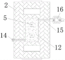
Referring to fig. 1-4, a metal mold for facilitating rapid mold stripping includes a first mold 1, a second mold 2, a liquid inlet pipe 3 and a connecting plate 4; the inner part of the second die 2 is symmetrically connected with a first push rod 5 in a sliding way, one end of the first push rod 5 extending to the outer side of the second die 2 is fixed on a connecting rod 6, the connecting rod 6 is fixed on an output shaft of a first electric push rod 7, and the first electric push rod 7 is fixed on the connecting plate 4 through a bolt, the second push rod 8 is symmetrically arranged in the first die 1 in a sliding way, the outer end of the second push rod 8 is fixed on the movable frame 9, the outer ends of the movable frame 9 are all fixed on the output end of the second electric push rod 11, the second electric push rod 11 is fixed on the side wall of the lower part of the first mould 1 through bolts, the second mould 2 and the first mould 1 outside the first push rod 5 and the second push rod 8 are both provided with cooling structures, the second push rod 8 is matched with the first push rod 5, so that the workpiece is quickly pushed to be separated from the first die 1 and the second die 2, and the die stripping speed of the metal die is improved;
the cooling structure comprises a first cooling cavity 12 and a second cooling cavity 13, a first cooling cavity 12 is formed in a second mold 2 on the outer side of each first push rod 5, second cooling cavities 13 are formed in first molds 1 on the outer sides of an upper second push rod 8 and a lower second push rod 8, the front ends and the rear ends of the upper second cooling cavity 13 and the lower second cooling cavity 13 are communicated through grooves, water inlets 15 are fixed at the top ends of the rear sides of the first cooling cavity 12 and the second cooling cavity 13, the rear ends of the water inlets 15 are fixed at the outlet end of a water suction pump 16, water outlets 14 are fixed at the bottom ends of the front sides of the first cooling cavity 12 and the second cooling cavity 13, and after the injection molding of the tool is completed, the workpiece is cooled, so that the workpiece can be rapidly cooled after the injection molding of the tool is completed; a 'return' groove matched with the moving frame 9 is formed in the first die 1, and the first push rod 5 and the second push rod 8 are both transversely arranged in a 'T' shape, so that the upper and lower second push rods 8 can be conveniently connected; the front side and the rear side of the upper end and the lower end of the movable frame 9 are both connected with fixed rods 10 in a sliding manner, two ends of each fixed rod 10 are both fixed on the side wall of the 'return' groove, and the movable frame 9 is limited by the fixed rods 10, so that the movable frame 9 can move more stably; the output ends of the water outlets 14 are connected with a waste water tank, and the inlet ends of the water pumps 16 are connected with a cold water tank, so that cold water can conveniently flow into the first cooling cavity 12 and the second cooling cavity 13, and cooled waste water can be conveniently discharged; the first cooling cavities 12 are all arranged in a shape of a Chinese character 'ri' matched with the two first push rods 5, the second cooling cavities 13 are arranged in a shape of a Chinese character 'mu' matched with the two second push rods 8, the height of the middle parts of the second cooling cavities 13 is larger than that of the liquid inlet pipe 3, so that the first cooling cavities 12 and the second cooling cavities 13 are communicated with each other, cold water flows conveniently, and a workpiece is cooled conveniently; leading to groove has all been seted up to side around first cooling chamber 12 and the second cooling chamber 13, and first cooling chamber 12 and the second cooling chamber 13 front and back end all through leading to groove respectively with delivery port 14 and water inlet 15 through-connection, make things convenient for suction pump 16 to first cooling chamber 12 and the inside cold water that pours into of second cooling chamber 13 into, also make things convenient for the inside cold water discharge in first cooling chamber 12 and the second cooling chamber 13 to cool down the work piece through mobile cold water.
When the injection molding machine is used, injection molding liquid enters a space between a first mold 1 and a second mold 2 through a liquid inlet pipe 3 for injection molding, when the injection molding is finished, water suction pumps 16 are turned on through external switches, so that the two water suction pumps 16 operate to suck cold water in a cold water tank into a first cooling cavity 12 and a second cooling cavity 13, a workpiece can be cooled through the cold water in the first cooling cavity 12 and the second cooling cavity 13, meanwhile, cooled wastewater is discharged into a wastewater tank through a water outlet 14, after the cooling is finished, when the first mold 1 is separated from the second mold 2, a second electric push rod 11 is controlled through the external switches, the second electric push rod 11 operates to push a movable frame 9, the movable frame 9 drives a second push rod 8 to push the workpiece to be separated from the first mold 1, the workpiece is clamped on the second mold 2 at the moment, and then the first electric push rod 7 is turned on through an external control switch, make the operation of first electric putter 7 promote first push rod 5 through connecting rod 6, can be through first push rod 5 with work piece and second mould 2 quickly separating to make things convenient for metal mold demolding, the electrical components that appear in this application all external intercommunication power and control switch when using.
The application has the advantages that:
1. the injection molding machine is simple to operate, the workpiece is pushed to be separated from the first mold 1 through the second push rod 8, the first mold 1 is prevented from being clamped with the first mold 1, the workpiece is pushed to be separated from the second mold 2 through the first push rod 5, the workpiece is convenient to rapidly remove after injection molding is completed, and the practicability of a metal mold is improved;
2. this application is rational in infrastructure, through the inside mobility cooling of first cooling chamber 12 and second cooling chamber 13, can mould plastics at the instrument and accomplish the back, carries out cooling to the work piece for the work piece can be qualitative in rapid cooling after the completion of moulding plastics, causes to collide with because of the work piece is indeterminate when avoiding demolding.
It is well within the skill of those in the art to implement, without undue experimentation, the present application is not directed to software and process improvements, as they relate to circuits and electronic components and modules.
The above description is only a preferred embodiment of the present application and is not intended to limit the present application, and various modifications and changes may be made by those skilled in the art. Any modification, equivalent replacement, improvement and the like made within the spirit and principle of the present application shall be included in the protection scope of the present application.