SUMMERY OF THE UTILITY MODEL
In order to solve at least one problem mentioned in the background art, the application provides a handle and a cooking utensil, can shelter from the fastener on the handle and insulate against heat, prevents that the fastener from scalding the user, improves the security of handle and cooking utensil.
In order to achieve the above object, in a first aspect, the present application provides a handle, including a housing, the housing has a containing cavity, a portion of the housing is recessed toward a side close to the containing cavity, an assembling cavity is formed on a side of the housing away from the containing cavity, a mounting hole is opened on a bottom wall of the assembling cavity, and the mounting hole communicates with the assembling cavity and the containing cavity.
The fastener is located in the assembling cavity and penetrates through the mounting hole, and the fastener is used for being connected with a part to be assembled in the accommodating cavity.
One side of the fastener, which is far away from the accommodating cavity, is provided with a heat insulation piece, and the orthographic projection of the heat insulation piece on the bottom wall of the assembling cavity covers the whole orthographic projection of the fastener on the bottom wall of the assembling cavity.
The handle that this application embodiment provided through set up the assembly chamber on the casing, opens the mounting hole in the assembly chamber, can make the fastener be arranged in the assembly chamber, and the at utmost avoids the fastener to expose. Set up the heat insulating part through keeping away from one side that holds the chamber at the fastener, can be thermal-insulated at the "afterbody" of fastener on the one hand, avoid the fastener to scald the user, on the other hand can shelter from the remaining exposed part of fastener, improves the outward appearance aesthetic property of handle.
In one possible implementation, the thermal insulation is located in the assembly chamber.
Therefore, the heat insulation piece has an assembly space, and the influence of the heat insulation piece on the appearance attractiveness of the handle is avoided.
In one possible implementation, the thermal insulation element and the assembly cavity are connected in an interference fit.
Thus, on the one hand, the heat insulation piece and the assembling cavity are assembled more conveniently, and on the other hand, the heat insulation piece is assembled more stably.
In one possible implementation manner, the heat insulation piece comprises a guide section and an assembly section which are connected with each other, the guide section is located between the assembly section and the fastening piece, and the assembly section is connected with the assembly cavity in an interference fit mode.
Thus, the heat insulating member can be assembled more conveniently.
In one possible implementation, the cross-sectional area of the guide section increases from the end close to the fastener to the end far from the fastener in a direction perpendicular to the bottom wall of the assembly cavity.
Therefore, during assembly, the heat insulation piece can slide into the assembly cavity along the guide section, and the assembly difficulty of the heat insulation piece is reduced.
In one possible implementation, the interference of the interference fit between the thermal insulation piece and the assembly cavity is between 0.1 and 0.6 mm.
Therefore, on one hand, the heat insulation piece and the assembly cavity are convenient to assemble, and on the other hand, the heat insulation piece and the assembly cavity are more stably connected.
In one possible embodiment, the surface of the insulating element on the side facing away from the receiving space is flush with the outer surface of the housing.
Thus, the outer surface of the shell can be smooth, and the appearance of the handle is improved.
In one possible implementation, the side walls of the assembly cavity are uneven.
Thus, the frictional force between the heat insulator and the fitting chamber can be increased, thereby improving the coupling stability of the heat insulator and the fitting chamber.
In a possible implementation, two assembly cavities are arranged on the housing at intervals, and a fastening piece and a heat insulation piece are arranged in each assembly cavity.
The handle still includes the connecting piece, and the both ends of connecting piece are connected with two heat insulating material respectively.
Therefore, the assembly of the two heat insulation pieces can be facilitated, and the assembly efficiency of the handle is improved.
In a possible implementation manner, one side of the shell, which is far away from the accommodating cavity, is provided with a recessed portion, the recessed portion is communicated with the two assembling cavities, the connecting piece is located in the recessed portion, and the surface of the connecting piece, which is far away from the accommodating cavity, is flush with the outer surface of the shell.
Therefore, the connecting piece can be positioned in the concave part, the connecting piece is prevented from protruding out of the surface of the shell, and the appearance attractiveness of the handle is improved.
In a possible implementation manner, a bonding piece is arranged between the connecting piece and the concave part, and the bonding piece is connected with the connecting piece and the concave part.
Therefore, the connecting piece and the shell can be connected more stably, and the connection stability of the heat insulation piece and the connecting piece and the shell is improved.
In one possible implementation, the thermal insulation member and the connecting member are both rubber members.
Therefore, on one hand, the heat insulation plate is convenient to process and manufacture, and on the other hand, the heat insulation plate can have a good heat insulation effect.
In one possible implementation, the thickness of the insulation is between 1.5-3 mm.
And/or the thickness of the connecting piece is between 0.8 and 1.5 mm.
Therefore, on one hand, the heat insulation effect is good, and on the other hand, the material cost can be reduced.
The second aspect, the application provides a cooking utensil, including the pot body and foretell handle, one side of the pot body is provided with the handle support, and the handle support is arranged in holding the chamber of handle, and the mounting hole and the handle leg joint of handle are worn to establish by the fastener.
The cooking utensil that this application embodiment provided through set up the assembly chamber on the casing, opens the mounting hole in the assembly chamber, can make the fastener be located the assembly chamber, and the at utmost avoids the fastener to expose. Set up the heat insulating part through keeping away from one side that holds the chamber at the fastener, can be thermal-insulated at the "afterbody" of fastener on the one hand, avoid the fastener to scald the user, on the other hand can shelter from the remaining exposed part of fastener, improves the outward appearance aesthetic property of handle.
The construction of the present application and other objects and advantages thereof will be more apparent from the following description of the preferred embodiments taken in conjunction with the accompanying drawings.
Detailed Description
As described in the background art, in the related art, the handle is connected with the handle bracket of the pot body through the screw, after the assembly is completed, the tail part of the screw is exposed on the outer surface of the handle, and the screw and the handle bracket are made of metal, so that the heat of the pot body can be transferred to the screw through the handle bracket, the screw is hot, when a user holds the handle, the risk of scalding by the screw exists, and the safety of the cooking appliance is reduced.
Based on foretell technical problem, handle and cooking utensil that this application provided through set up the assembly chamber on the casing, set up the mounting hole in the assembly chamber, can make the fastener be arranged in the assembly chamber, and the at utmost avoids the fastener to expose. Set up the heat insulating part through keeping away from one side that holds the chamber at the fastener, can be thermal-insulated at the "afterbody" of fastener on the one hand, avoid the fastener to scald the user, on the other hand can shelter from the remaining exposed part of fastener, improves the outward appearance aesthetic property of handle.
In order to make the objects, technical solutions and advantages of the present application clearer, the technical solutions in the embodiments of the present application will be described in more detail below with reference to the accompanying drawings in the preferred embodiments of the present application. In the drawings, the same or similar reference numerals denote the same or similar components or components having the same or similar functions throughout. The described embodiments are a subset of the embodiments in the present application and not all embodiments in the present application. The embodiments described below with reference to the drawings are exemplary and intended to be used for explaining the present application and should not be construed as limiting the present application. All other embodiments, which can be derived by a person skilled in the art from the embodiments given herein without making any creative effort, shall fall within the protection scope of the present application. Embodiments of the present application will be described in detail below with reference to the accompanying drawings.
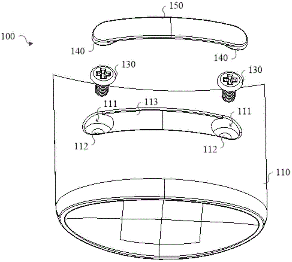
Fig. 1 is an exploded view of a handle provided in an embodiment of the present application. Fig. 2 is a schematic cross-sectional view of a handle provided in an embodiment of the present application. Fig. 3 is a schematic cross-sectional view of a handle provided in an embodiment of the present application in an exploded state. FIG. 4 is a top view of an insulation and connector for a handle provided by an embodiment of the present application. Fig. 5 is a schematic structural diagram of an insulation member of a handle according to an embodiment of the present disclosure. Fig. 6 is a partial structural schematic view of a housing of a handle according to an embodiment of the present application. Referring to fig. 1-6, embodiments of the present application provide a handle.
As shown in fig. 1 and 2, the handle 100 includes a housing 110, the housing 110 has a receiving cavity 120, a portion of the housing 110 is recessed toward a side close to the receiving cavity 120, a mounting cavity 111 is formed on a side of the housing 110 away from the receiving cavity 120, a mounting hole 112 is opened on a bottom wall 111a of the mounting cavity 111, and the mounting hole 112 communicates the mounting cavity 111 and the receiving cavity 120.
The fastener 130 is positioned in the assembling cavity 111 and penetrates through the mounting hole 112, and the fastener 130 is used for being connected with a part to be assembled in the accommodating cavity 120. The side of the fastening member 130 far from the accommodating chamber 120 is provided with the heat insulation member 140, and the orthographic projection of the heat insulation member 140 on the bottom wall 111a of the assembling chamber 111 covers the whole orthographic projection of the fastening member 130 on the bottom wall 111a of the assembling chamber 111, so that the heat insulation member 140 can completely shield and insulate the tail part of the fastening member 130, and the fastening member 130 is prevented from being exposed.
In the embodiment of the present application, the handle bracket 210 of the pot body is the assembly member, and the fastening member 130 is a screw, and when the assembly member is assembled, the handle bracket 210 can be inserted into the receiving cavity 120 of the handle 100, and the handle 100 is connected to the handle bracket 210 by the screw.
It should be noted that, by providing the assembly cavity 111 on the housing 110 and opening the mounting hole 112 in the assembly cavity 111, the fastener 130 has a mounting position, and can be located in the assembly cavity 111 after assembly, so that most of the structure of the fastener 130 can be hidden in the assembly cavity 111, and the fastener 130 is prevented from being exposed to the greatest extent. By arranging the heat insulation member 140 on the side of the fastening member 130 far away from the accommodating cavity 120, on one hand, the heat insulation can be performed on the 'tail' of the fastening member 130, so that the user can be prevented from being scalded by the fastening member 130, and on the other hand, the remaining structure of the fastening member 130 can be shielded, so that the appearance attractiveness of the handle 100 is improved.
It is understood that the heat insulation member 140 may be disposed on the housing 110, and for example, the heat insulation member 140 may be adhered to the outer surface of the housing 110. The embodiment of the present application does not limit the specific arrangement manner of the heat insulation member 140.
In one possible implementation, the thermal insulation 140 is located in the assembly chamber 111. Thus, the heat insulation member 140 has an assembly space on the housing 110, and shares the same assembly cavity 111 with the fastening member 130, so that the heat insulation member 140 can be assembled more conveniently, and the heat insulation member 140 is prevented from affecting the appearance of the handle 100.
In one possible implementation, the thermal insulation members 140 and the assembly cavity 111 are connected by an interference fit. Through the interference fit connection, on one hand, the heat insulation piece 140 and the assembling cavity 111 are more conveniently assembled, and on the other hand, the heat insulation piece 140 is more stably assembled and is easy to disassemble.
Specifically, as shown in fig. 5, the heat insulation member 140 may include a guide section 141 and a fitting section 142 connected to each other, the guide section 141 is located between the fitting section 142 and the fastening member 130, and the fitting section 142 is connected to the fitting cavity 111 in an interference fit manner. By providing the guide section 141, the guide section 141 can play a role of guiding when the heat insulating member 140 is assembled, so that the heat insulating member 140 is more conveniently assembled.
It is understood that the guide segment 141 may be cylindrical, and the diameter of the guide segment 141 may be smaller than that of the assembling segment 142, and the shape of the guide segment 141 is not limited in the embodiment of the present application.
In one possible implementation, the cross-sectional area of the guide section 141 is gradually increased from an end close to the fastener 130 to an end far from the fastener 130 in a direction perpendicular to the bottom wall 111a of the fitting cavity 111. Thus, during assembly, the heat insulation member 140 can be inserted into the assembly cavity 111 along the guide section 141, and the assembly difficulty of the heat insulation member 140 is reduced. Illustratively, the guide section 141 may be shaped like a conical cylinder.
In one possible implementation, the interference of the thermal insulation member 140 and the assembly cavity 111 is between 0.1mm and 0.6mm, wherein the interference may be 0.1mm, 0.3mm, 0.5mm, or 0.6 mm. If the interference is less than 0.1mm, the pressing force after the heat insulating member 140 and the assembly chamber 111 are assembled is insufficient, resulting in unstable connection between the heat insulating member 140 and the assembly chamber 111. If the interference magnitude is greater than 0.6mm, the heat insulation member 140 is not easy to enter the assembly cavity 111 during assembly, which results in greater assembly difficulty. Illustratively, the diameter of the assembly cavity 111 may be 10mm and the diameter of the thermal shield 140 may be 10.5 mm.
Specifically, the surface of the heat insulating member 140 on the side away from the accommodating chamber 120 is flush with the outer surface of the housing 110. Thus, after the heat insulation member 140 is assembled, the heat insulation member 140 is prevented from protruding out of the outer surface of the housing 110, and the junction between the outer surface of the heat insulation member 140 and the outer surface of the housing 110 can be smoothly transited. On the one hand, improves the gripping comfort of the handle 100 and, on the other hand, improves the aesthetic appearance of the handle 100.
In one possible implementation, as shown in fig. 6, the side wall 111b of the fitting cavity 111 is uneven. Illustratively, the sidewall 111b of the assembly chamber 111 may be indented or wavy. Thus, the frictional force at the junction of the heat insulating member 140 and the assembly chamber 111 can be increased, so that the junction of the heat insulating member 140 and the assembly chamber 111 can be more stably connected, and the stability of the junction of the heat insulating member 140 and the assembly chamber 111 can be improved.
In the embodiment of the present application, two assembly cavities 111 are provided on the housing 110, and each assembly cavity 111 has a fastening member 130 and a heat insulating member 140 provided therein. By providing two fasteners 130, the handle 100 and the handle bracket 210 can be more securely connected. The handle 100 further includes a connection member 150, and both ends of the connection member 150 are connected to the two heat insulators 140, respectively. Thus, the two heat insulators 140 can be coupled, and the two heat insulators 140 and the coupling member 150 can be simultaneously assembled when assembling the heat insulators 140, so that the assembly of the heat insulators 140 is more convenient and the assembly efficiency of the handle 100 is improved, compared with the assembly of the two heat insulators 140 separately.
It will be appreciated that the connection 150 may be provided in a variety of ways, such as: the connecting member 150 is adhered to the outer surface of the housing 110 by glue, and the arrangement of the connecting member 150 is not limited in this embodiment.
In a possible implementation manner, a recessed portion 113 is provided at a side of the housing 110 away from the accommodating cavity 120, two ends of the recessed portion 113 are respectively communicated with the two assembling cavities 111, the connecting member 150 is located in the recessed portion 113, and a surface of the connecting member 150 at a side away from the accommodating cavity 120 is flush with an outer surface of the housing 110.
It should be noted that, by providing the recess 113, the connector 150 has an assembly space, and can be located in the recess 113, so as to prevent the connector 150 from protruding out of the outer surface of the housing 110, and to enable the connection between the outer surface of the connector 150 and the outer surface of the housing 110 to be smoothly transited. On the one hand, improves the gripping comfort of the handle 100 and, on the other hand, improves the aesthetic appearance of the handle 100.
In one possible implementation, as shown in fig. 3, an adhesive 160 may be disposed between the connection member 150 and the recess 113, and the adhesive 160 connects the connection member 150 and the recess 113. The adhesive member 160 may be a double-sided tape, a solid glue, or a liquid glue, and the embodiment of the present application does not limit the kind of the adhesive member 160. By providing the adhesive member 160, the connection between the connector 150 and the housing 110 can be more stable, thereby improving the connection stability between the heat insulation member 140 and the connector 150 and the housing 110.
In one possible implementation, the thermal insulation members 140 and the connection members 150 are both rubber members. Therefore, on one hand, the heat insulation piece 140 and the connecting piece 150 are convenient to be integrally processed, and on the other hand, the heat insulation piece 140 has a good heat insulation effect.
For example, the heat insulation member 140 and the connection member 150 may be made of silicone, and particularly, may be made of silicone, so that the heat insulation member 140 and the connection member 150 have good temperature resistance, and excellent weather resistance and insulation performance. In addition, the material of the heat insulation member 140 and the connection member 150 may also be styrene butadiene rubber or nitrile butadiene rubber, and the specific material of the heat insulation member 140 and the connection member 150 is not limited in the embodiment of the application, and a user may select the material according to the actual situation.
In one possible implementation, the thickness of the thermal insulation members 140 is between 1.5-3mm, wherein the thickness may be 1.5mm, 2mm, or 3 mm. If the thickness of the heat insulating member 140 is less than 1.5mm, the heat insulating performance of the heat insulating member 140 is limited, and a user may easily get burned when holding the handle 100. Since the heat insulator 140 is positioned in the assembly chamber 111, if the thickness of the heat insulator 140 is greater than 3mm, the space of the assembly chamber 111 is increased, resulting in a decrease in the structural strength of the case 110.
In one possible implementation, the thickness of the connector 150 is between 0.8-1.5mm, wherein the thickness may be 0.8mm, 1mm, or 1.5 mm. If the thickness of the connection member 150 is less than 0.8mm, the strength of the connection member 150 is too low, resulting in the connection member 150 being vulnerable to damage. Since the connection member 150 is positioned in the recess 113, if the thickness of the connection member 150 is greater than 1.5mm, the space of the recess 113 is increased, resulting in a decrease in the structural strength of the housing 110.
It can be understood that the thickness of the heat insulation member 140 and the connecting member 150 is within the above range, which can provide the heat insulation member 140 with a better heat insulation effect and reduce the material cost.
As shown in FIG. 4, in the embodiment of the present invention, the two heat insulation members 140 and the connecting member 150 are integrally formed, so that a complete shielding member can be formed, and the shielding member can shield the fastening member 130, thereby preventing the tail portion of the fastening member 130 from being exposed to the outside and scalding the user. In order to optimize the design of the handle 100, the width W of the connector 150 may be between 10-11mm and the distance L between the ends of the two thermal insulation members 140 that are away from each other may be between 50-60 mm. It is understood that the above-mentioned dimensions are all related to the arrangement of the fitting cavity 111 and the recess 113 on the housing 110, and the embodiment of the present application does not limit the width of the connecting member 150 and the distance between the two heat insulating members 140.
Referring to fig. 7, 8 and 9, in a second aspect, embodiments of the present application provide a cooking appliance, where the cooking appliance 300 may be an electric cooker or an electric stewpan. Specifically, the cooking utensil 300 includes a pot body 200 and the above-mentioned handle 100, a handle bracket 210 is disposed on one side of the pot body 200, the handle bracket 210 is located in the accommodating cavity 120 of the handle 100, and the fastener 130 penetrates through the mounting hole 112 of the handle 100 and is connected with the handle bracket 210. In addition, the pan body 200 can be further provided with a handle 220, and the handle 220 and the handle 100 are symmetrical to each other and are respectively located at two sides of the pan body 200. In this way, the user can conveniently take the cooking appliance 300.
According to the cooking appliance 300 provided by the embodiment of the application, the assembly cavity 111 is formed in the housing 110, and the mounting hole 112 is formed in the assembly cavity 111, so that the fastener 130 can be located in the assembly cavity 111, and the fastener 130 is prevented from being exposed to the greatest extent. By providing the heat insulation member 140 on the side of the fastening member 130 away from the accommodating cavity 120, on one hand, the "tail" of the fastening member 130 can be insulated to prevent the fastening member 130 from burning the user, and on the other hand, the fastening member 130 can be completely "hidden" to improve the aesthetic appearance of the handle 100.
In the description of the present application, it should be noted that unless otherwise specifically stated or limited, the terms "mounted," "connected," and "connected" are to be construed broadly, e.g., as meaning a fixed connection, an indirect connection through intervening media, a connection between two elements, or an interaction between two elements. The specific meaning of the above terms in the present application can be understood by those of ordinary skill in the art as appropriate. The terms "upper," "lower," "front," "rear," "vertical," "horizontal," "top," "bottom," "inner," "outer," and the like refer to an orientation or positional relationship indicated in the drawings for convenience in describing the present application and to simplify description, but do not indicate or imply that the referenced device or element must have a particular orientation, be constructed and operated in a particular orientation, and thus should not be construed as limiting the present application. In the description of the present application, "a plurality" means two or more unless specifically stated otherwise.
The terms "first," "second," "third," "fourth," and the like in the description and in the claims of the present application and in the drawings described above, if any, are used for distinguishing between similar elements and not necessarily for describing a particular sequential or chronological order. It is to be understood that the data so used is interchangeable under appropriate circumstances such that the embodiments of the application described herein are, for example, capable of operation in sequences other than those illustrated or otherwise described herein. Furthermore, the terms "comprises," "comprising," and "having," and any variations thereof, are intended to cover a non-exclusive inclusion, such that a process, method, system, article, or apparatus that comprises a list of steps or elements is not necessarily limited to those steps or elements expressly listed, but may include other steps or elements not expressly listed or inherent to such process, method, article, or apparatus.
Finally, it should be noted that: the above embodiments are only used for illustrating the technical solutions of the present application, and not for limiting the same; although the present application has been described in detail with reference to the foregoing embodiments, it should be understood by those of ordinary skill in the art that: the technical solutions described in the foregoing embodiments may still be modified, or some or all of the technical features may be equivalently replaced; and the modifications or the substitutions do not make the essence of the corresponding technical solutions depart from the scope of the technical solutions of the embodiments of the present application.