CN216351016U - Power transmission and distribution network fault monitoring device - Google Patents
Power transmission and distribution network fault monitoring device Download PDFInfo
- Publication number
- CN216351016U CN216351016U CN202122490847.0U CN202122490847U CN216351016U CN 216351016 U CN216351016 U CN 216351016U CN 202122490847 U CN202122490847 U CN 202122490847U CN 216351016 U CN216351016 U CN 216351016U
- Authority
- CN
- China
- Prior art keywords
- mounting
- buffering
- distribution network
- clamping ring
- heat dissipation
- Prior art date
- Legal status (The legal status is an assumption and is not a legal conclusion. Google has not performed a legal analysis and makes no representation as to the accuracy of the status listed.)
- Expired - Fee Related
Links
- 238000009826 distribution Methods 0.000 title claims abstract description 27
- 238000012806 monitoring device Methods 0.000 title claims abstract description 21
- 230000005540 biological transmission Effects 0.000 title claims abstract description 18
- 230000017525 heat dissipation Effects 0.000 claims abstract description 34
- 238000007664 blowing Methods 0.000 claims abstract description 15
- 230000003139 buffering effect Effects 0.000 claims description 42
- 238000003860 storage Methods 0.000 claims description 14
- 230000035939 shock Effects 0.000 claims description 11
- 230000001681 protective effect Effects 0.000 claims description 6
- 230000000149 penetrating effect Effects 0.000 claims description 4
- 238000009434 installation Methods 0.000 claims 6
- 230000000694 effects Effects 0.000 abstract description 41
- 230000002035 prolonged effect Effects 0.000 abstract description 5
- 235000000621 Bidens tripartita Nutrition 0.000 description 6
- 240000004082 Bidens tripartita Species 0.000 description 6
- 238000001816 cooling Methods 0.000 description 6
- 208000006637 fused teeth Diseases 0.000 description 6
- 238000010521 absorption reaction Methods 0.000 description 3
- 230000009471 action Effects 0.000 description 3
- 240000007643 Phytolacca americana Species 0.000 description 2
- 235000009074 Phytolacca americana Nutrition 0.000 description 2
- 239000000428 dust Substances 0.000 description 2
- 230000001771 impaired effect Effects 0.000 description 2
- 230000001133 acceleration Effects 0.000 description 1
- 230000009286 beneficial effect Effects 0.000 description 1
- 238000013016 damping Methods 0.000 description 1
- 238000004880 explosion Methods 0.000 description 1
- 238000004519 manufacturing process Methods 0.000 description 1
- 238000012986 modification Methods 0.000 description 1
- 230000004048 modification Effects 0.000 description 1
- 238000012544 monitoring process Methods 0.000 description 1
- 230000002265 prevention Effects 0.000 description 1
- 230000009467 reduction Effects 0.000 description 1
- 238000005096 rolling process Methods 0.000 description 1
- 238000013024 troubleshooting Methods 0.000 description 1
- 239000002699 waste material Substances 0.000 description 1
Images



Classifications
-
- Y—GENERAL TAGGING OF NEW TECHNOLOGICAL DEVELOPMENTS; GENERAL TAGGING OF CROSS-SECTIONAL TECHNOLOGIES SPANNING OVER SEVERAL SECTIONS OF THE IPC; TECHNICAL SUBJECTS COVERED BY FORMER USPC CROSS-REFERENCE ART COLLECTIONS [XRACs] AND DIGESTS
- Y02—TECHNOLOGIES OR APPLICATIONS FOR MITIGATION OR ADAPTATION AGAINST CLIMATE CHANGE
- Y02E—REDUCTION OF GREENHOUSE GAS [GHG] EMISSIONS, RELATED TO ENERGY GENERATION, TRANSMISSION OR DISTRIBUTION
- Y02E10/00—Energy generation through renewable energy sources
- Y02E10/50—Photovoltaic [PV] energy
- Y02E10/56—Power conversion systems, e.g. maximum power point trackers
Landscapes
- Cooling Or The Like Of Electrical Apparatus (AREA)
Abstract
The utility model discloses a power transmission and distribution network fault monitoring device, relates to the field of monitoring devices, and aims to solve the problems that an existing power distribution network monitoring device is simple in structure and poor in heat dissipation effect. The heat dissipation device is novel in structure, the heat dissipation device is provided with the heat dissipation device, air circulation in the shell is accelerated through the matching of the suction fan and the blowing fan, the heat dissipation efficiency is improved, the service life of the device is prolonged, and the heat dissipation device is convenient for workers to disassemble and assemble through the arrangement of the clamping device and the fixing structure.
Description
Technical Field
The utility model relates to the field of monitoring devices, in particular to a power transmission and distribution network fault monitoring device.
Background
The distribution network is an electric power network which receives electric energy from a transmission network or a regional power plant and distributes the electric energy to various users on site through distribution facilities or step by step according to voltage. The power distribution network consists of overhead lines, cables, towers, distribution transformers, isolating switches, reactive power compensators, accessory facilities and the like, and plays a role in distributing electric energy in a power network. The power distribution network generally adopts a closed-loop design and an open-loop operation, and the structure of the power distribution network is radial. The closed loop structure is adopted to improve the flexibility of operation and the reliability of power supply; open loop operation is on the one hand in order to restrict the short circuit fault current, prevents that the circuit breaker from surpassing the breaking capacity and taking place the explosion, and on the other hand is control fault spread scope, helps avoiding the trouble to cut off the power supply range and enlarges, in the power transmission process, for guaranteeing the normal clear of carrying, often need carry out the troubleshooting to the power distribution network.
But current distribution network monitoring devices simple structure is in external environment for a long time, and the radiating effect is not good, and the device uses for a long time, and self production heat and external heat can cause the device to overheat and damage, reduce device life. Therefore, in order to solve the above problems, we propose a transmission and distribution network fault monitoring device.
SUMMERY OF THE UTILITY MODEL
The power transmission and distribution network fault monitoring device provided by the utility model solves the problems of simple structure and poor heat dissipation effect of the existing power distribution network monitoring device.
In order to achieve the purpose, the utility model adopts the following technical scheme:
power transmission and distribution network fault monitoring device, including casing, detector and photovoltaic board, casing one side fixed mounting has the mounting box, just install clamping device in the mounting box, fixed mounting has the pillar in the casing, just pillar top fixed mounting has the mounting panel, monitor fixed mounting is on the mounting panel top, just the heat dissipation window has all been seted up to casing both sides inner wall, two equal fixed mounting has the filter screen in the heat dissipation window, just the monitor top runs through the casing, shells inner wall is equipped with heat abstractor, be equipped with buffer between casing top and the photovoltaic board.
Through adopting the above technical scheme, the device is during the use, the staff passes through clamping device's cooperation, install the device in the position that needs the monitoring, when the device is used for a long time, self can produce the heat, heat abstractor passes through the heat dissipation window, circulation of air in the casing accelerates, make cold and hot air exchange, the effect of heat dissipation cooling is played, help avoiding the device to lead to casing internal component to damage because of the high temperature, the service life of the device is prolonged, and produce the electric energy through photovoltaic board absorption light energy, provide kinetic energy for the device, energy-concerving and environment-protective, the practicality of the device has been improved, and the photovoltaic board bottom is equipped with buffer, can play the effect of shock attenuation buffering, reach protection device's effect, the service life of the device is prolonged.
Preferably, clamping device includes two tooth screw rods, a piece, first clamp ring, second clamp ring and fixed disk, two tooth screw rods rotate and install in the mounting box, just fixed disk fixed mounting runs through the one end of mounting box in two tooth screw rods, and is equipped with fixed knot between the relative one side of fixed disk and mounting box and constructs, mounting box one side fixed mounting is kept away from to the fixed disk has the handle, and two tooth screw rods are located to a piece thread bush the mounting box is all run through to shell one side is kept away from to a piece, just first clamp ring and second clamp ring are installed respectively in two a piece runs through mounting box one side, two sections screw threads of two tooth screw rods are opposite.
Through adopting above-mentioned technical scheme, the staff passes through the handle and rotates the fixed disk, the two tooth screw rods of fixed disk drive rotate, make two piece relative movement, take first clamp ring and second clamp ring relative movement through two piece, be convenient for install the device in the position that needs detected, and play the effect of fixed rolling disc through fixed knot structure, the stability of device has been improved, and first clamp ring all is the semicircular with the second clamp ring, the centre gripping of being convenient for is fixed on not unidimensional cylinder, the practicality of device has been improved.
Preferably, the second clamping ring is far away from one side of the first clamping ring and is provided with a fixing bolt in a threaded manner, one end, close to the second clamping ring, of the fixing bolt penetrates through the first clamping ring, and a threaded hole matched with the fixing bolt is formed in the side wall of one end, far away from the mounting box, of the second clamping ring.
Through adopting above-mentioned technical scheme, through fixing bolt and fixed orifices spiral shell, can further play the effect of fixed first clamp ring and second clamp ring, improve the stability of device.
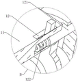
Preferably, fixed knot structure accomodates the groove, supports position spring and dead lever, accomodate the groove and offer in the mounting box and be close to fixed disk one side, just dead lever slidable mounting is in accomodating the inslot, it keeps away from fixed disk one end and accomodates between the one side inner wall that the groove is relative to the dead lever to support position spring mounting, just the fixed disk is close to mounting box one side and is seted up the fixed slot that just is the ring array and distributes with the dead lever phase-match, just dead lever lateral wall fixed mounting has the poker rod, the poker rod is kept away from dead lever one end and is slided and run through and accomodate the groove.
Through adopting above-mentioned technical scheme, when application clamping device, the staff moves the pole drive dead lever to accomodating the inslot and remove through the poker, makes dead lever and corresponding fixed slot break away from the block state, and the staff of being convenient for rotates two tooth screw rods, and after the fixed completion of device, the staff loosens the poker pole, and the dead lever makes dead lever and corresponding fixed slot block under the effect of the spring that supports, plays the effect of fixed disk, has improved the stability of device.
Preferably, the heat dissipation device comprises a mounting frame, a suction fan and a blowing fan, two mounting frames which are the same in structure and are symmetrically distributed are fixedly mounted in the shell, the two mounting frames are close to the heat dissipation windows on the two sides respectively, and the two mounting frames are respectively provided with the suction fan and the blowing fan.
Through adopting above-mentioned technical scheme, when the device is inside to produce high temperature, in with external cold air suction casing through the blower fan, simultaneously, derive the hot-air of casing through blowing the fan, through the cooperation of blower fan with the fan of blowing, the circulation of air in the acceleration casing reaches cold and hot exchange's effect, plays the effect of heat dissipation cooling, has improved the life of device.
Preferably, buffer includes buffering post, buffer beam and spliced pole, four groups buffering post fixed mounting in casing top four corners, just the movable groove has all been seted up on buffering post top, buffer beam slidable mounting is in the movable groove, just buffer beam bottom with organize with equal fixedly connected with buffer spring, two between the inner wall of movable groove bottom spliced pole fixed mounting is wherein two the buffer beam top, and two spliced pole and other two the buffer beam top all rotates with the photovoltaic board bottom and is connected.
Through adopting above-mentioned technical scheme, through buffering post, buffer beam and buffer spring's cooperation, play the effect of shock attenuation buffering, when the photovoltaic board receives external striking, can play the effect of shock attenuation buffering, improved the life of device.
Preferably, the equal fixed mounting in buffering post bottom has the threaded rod, just casing top four corners all seted up with the threaded groove of same group threaded rod assorted, mounting panel top fixed mounting has the battery, just photovoltaic board and battery electric connection, the protection casing is installed on photovoltaic board top, just the protection casing is the transparence.
Through adopting above-mentioned technical scheme, the threaded rod is installed in the rotation of buffering post bottom, and the staff makes threaded rod and the threaded rod screw thread that corresponds through aiming at the corresponding thread groove of casing with the threaded rod, reaches the effect of fixed buffering post, and the staff's dismouting of being convenient for has improved work efficiency, and the photovoltaic board top is equipped with the protection casing, plays the effect of protection photovoltaic board, helps avoiding the photovoltaic board impaired, has improved the life of photovoltaic board.
Preferably, the bottom end of the mounting plate is fixedly provided with shock pads which are identical in structure and distributed in a rectangular array, and the bottom end of the shell is provided with heat dissipation holes which are identical in structure and distributed in a rectangular array.
Through adopting above-mentioned technical scheme, through the setting of shock pad, play the effect of shock attenuation buffering, reach protection device's effect, and the hot-air accessible louvre effluvium in the casing plays the effect of heat dissipation cooling.
The utility model has the beneficial effects that:
through heat abstractor's setting, utilize in the induced-draught fan inhales the casing with the cold air in the external world, the cold air acts on the monitor, play radiating effect, and simultaneously, utilize the fan of blowing to derive the heat in the casing external, promote circulation of air in the casing, reach the effect of heat exchange, the radiating efficiency has been improved, help avoiding the device to use for a long time, make casing internal member damage because of high temperature, the service life of the device has been improved, and through the setting of louvre, the heat of being convenient for is derived, and the radiating efficiency is improved.
Through the setting of photovoltaic board, utilize the photovoltaic board to convert solar energy into the electric energy and store, play and provide the effect of electric energy for the device, reach self-sufficient effect, energy-concerving and environment-protective, the practicality of device has been improved, and through the setting of clamping device and fixed knot structure, the staff of being convenient for fixes the device in corresponding position, work efficiency has been improved, and the staff dismouting of being convenient for, the practicality of device has been improved, and through protection casing and buffer's effect, play protection device's effect, device life has been improved.
To sum up, the device novel structure not only is equipped with heat abstractor, through the cooperation of suction fan and the fan of blowing, circulation of air in the casing has improved the radiating efficiency with higher speed, has improved the life of device, and through clamping device and fixed knot structure's setting, the staff's dismouting of being convenient for improves work efficiency.
Drawings
FIG. 1 is a schematic structural view of the present invention;
FIG. 2 is an enlarged view of A of FIG. 1 in accordance with the present invention;
FIG. 3 is a cross-sectional view of the present invention;
FIG. 4 is a cross-sectional view of the mounting box of the present invention;
FIG. 5 is an enlarged view of B of FIG. 4 in accordance with the present invention;
fig. 6 is a cross-sectional view of the housing of the present invention.
Reference numbers in the figures: 1. a housing; 2. a heat dissipation window; 3. a buffer column; 31. a buffer spring; 32. a movable groove; 4. a buffer rod; 5. a photovoltaic panel; 6. a monitor; 7. connecting columns; 8. a first clamp ring; 81. a threaded hole; 9. a second clamp ring; 91. fixing the bolt; 10. fixing the disc; 11. mounting a box; 12. a receiving groove; 122. a position-resisting spring; 121. fixing the rod; 13. mounting a plate; 14. a mounting frame; 15. a double-tooth screw; 16. supporting a block; 17. an air suction fan; 18. a blower fan; 19. a protective cover; 20. heat dissipation holes; 21. a shock pad; 22. and a support pillar.
Detailed Description
The technical solutions in the embodiments of the present invention will be clearly and completely described below with reference to the drawings in the embodiments of the present invention, and it is obvious that the described embodiments are only a part of the embodiments of the present invention, and not all of the embodiments.
Referring to fig. 1-3, a power transmission and distribution network fault monitoring device comprises a shell 1, a monitor 6 and a photovoltaic panel 5, wherein a mounting box 11 is fixedly mounted on one side of the shell 1, a clamping device is mounted in the mounting box 11 and plays a role in clamping and fixing, the device is convenient for workers to disassemble and assemble, the working efficiency is improved, a strut 22 is fixedly mounted in the shell 1, a mounting plate 13 is fixedly mounted at the top end of the strut 22, the monitor 6 is fixedly mounted at the top end of the mounting plate 13, heat dissipation windows 2 are respectively formed in the inner walls of two sides of the shell 1, filter screens are respectively and fixedly mounted in the two heat dissipation windows 2, air circulation is facilitated by the arrangement of the heat dissipation windows 2, the heat dissipation and temperature reduction effects are achieved, the filter screens can play a role in dust prevention, dust is favorably prevented from entering the shell 1, internal elements are enabled to be damaged, the service life of the device is prolonged, and the top end of the monitor 6 penetrates through the shell 1, the inner wall of the shell 1 is provided with a heat dissipation device which plays a role of heat dissipation and cooling through the arrangement of the heat dissipation device, thereby being conductive to avoiding the damage of the device due to high temperature, prolonging the service life of the device and improving the safety of the device, a buffer device is arranged between the top end of the shell 1 and the photovoltaic panel 5, the buffer device can play a role of shock absorption and buffering, thereby being conductive to avoiding the damage of the device due to impact, prolonging the service life of the device, the top end of the mounting plate 13 is fixedly provided with a storage battery, the photovoltaic panel 5 is electrically connected with the storage battery, the top end of the photovoltaic panel 5 is provided with a protective cover, the protective cover 19 is transparent, the bottom end of the mounting plate 13 is fixedly provided with a shock absorption pad 21 which has the same structure and is distributed in a rectangular array, the bottom end of the shell 1 is provided with heat dissipation holes 20 which have the same structure and are distributed in a rectangular array, and the photovoltaic panel 5 and the storage battery are arranged, thereby utilizing the photovoltaic panel 5 to convert solar energy into electric energy, provide kinetic energy for the device, reach self-sufficient effect, reduced the waste of electric energy, energy-concerving and environment-protective, and can play the effect of protection photovoltaic board 5 through the protection casing, help avoiding photovoltaic board 5 to receive the damage, improved the life of device.
Referring to fig. 1 and 3, the buffering device comprises buffering columns 3, buffering rods 4 and connecting columns 7, four groups of buffering columns 3 are fixedly arranged at four corners of the top end of a shell 1, movable grooves 32 are formed in the top ends of the buffering columns 3, the buffering rods 4 are slidably arranged in the movable grooves 32, buffering springs 31 are fixedly connected between the bottom ends of the buffering rods 4 and the inner walls of the bottom ends of the movable grooves 32 in the same group, two connecting columns 7 are fixedly arranged at the top ends of two buffering rods 4, the top ends of the two connecting columns 7 and the top ends of the other two buffering rods 4 are rotatably connected with the bottom end of a photovoltaic panel 5, threaded rods are fixedly arranged at the bottom ends of the buffering columns 3, threaded grooves matched with the threaded rods in the same group are formed in four corners of the top end of the shell 1, before the device is used, the threaded rods rotatably arranged at the bottom ends of the buffering columns 3 of workers align to the threaded grooves formed in the top end of the shell 1, with threaded rod and thread groove spiral shell, play the effect of fixed buffering post 3, the staff's dismouting of being convenient for improves work efficiency, and photovoltaic board 5 plays the effect of shock attenuation buffering under buffer beam 4 and buffer spring 31's effect, reduces photovoltaic board 5's impaired degree, has improved the life of device.
Referring to fig. 3-5, the clamping device includes a double-threaded screw 15, a supporting block 16, a first clamping ring 8, a second clamping ring 9 and a fixing plate 10, the double-threaded screw 15 is rotatably installed in the mounting box 11, the fixing plate 10 is fixedly installed at one end of the double-threaded screw 15 penetrating through the mounting box, a fixing structure is arranged between one side of the fixing plate 10 opposite to the mounting box 11, the fixing structure includes a storage groove 12, a position resisting spring 122 and a fixing rod 121, the storage groove 12 is arranged at one side of the mounting box 11 close to the fixing plate 10, the fixing rod 121 is slidably installed in the storage groove 12, the position resisting spring 122 is installed between one end of the fixing rod 121 far away from the fixing plate 10 and the inner wall of one side of the storage groove 12 opposite to the fixing plate, one side of the fixing plate 10 close to the mounting box 11 is provided with a fixing groove matched with the fixing rod 121 and distributed in an annular array, and a poking rod is fixedly installed at the side wall of the fixing rod 121, the shifting rod is far away from one end of the fixing rod 121 and penetrates through the containing groove 12 in a sliding mode, after the photovoltaic panel 5 is fixed, a worker shifts the fixing rod 121 to move into the containing groove 12 through the shifting rod, the fixing rod 121 is enabled to be separated from a corresponding fixing groove in a clamping mode, the worker can conveniently rotate the fixing disc 10, a handle is fixedly installed on one side, far away from the mounting box 11, of the fixing disc 10, two supporting blocks 16 are sleeved on two sections of the double-tooth screw 15 in a threaded mode, one side, far away from the shell 1, of each supporting block 16 penetrates through the mounting box 11, the first clamping ring 8 and the second clamping ring 9 are installed on one side, penetrating through the mounting box 11, of each supporting block 16, the two sections of threads of the double-tooth screw 15 are opposite, the worker rotates the fixing disc 10 through the handle, the fixing disc 10 drives the double-tooth screw 15, the threads of the double-tooth screw 15 are opposite, therefore, the two supporting blocks 16 are enabled to move relatively, the two supporting blocks 16 drive the first clamping ring 8 and the second clamping ring 9 to move reversely, the first clamping ring 8 and the second clamping ring 9 are conveniently wound on the side wall of the fixed column, after the first clamping ring 8 and the second clamping ring 9 are wound on the side wall of the fixed column, a worker reversely rotates the double-tooth screw 15 to enable the first clamping ring 8 and the second clamping ring 9 to relatively move to achieve the effect of clamping and fixing, after the distance is determined, the worker loosens the poke rod, the fixing rod 121 is clamped with the corresponding fixing groove under the action of the abutting spring 122 to achieve the effect of limiting the rotation of the fixing plate 10, the stability of the device is improved, a fixing bolt 91 is installed on one side, far away from the first clamping ring 8, of the second clamping ring 9 in a threaded mode, one end, close to the second clamping ring 9, of the second clamping ring 9 penetrates through the first clamping ring 8, one end, far away from the mounting box 11, of the side wall of the second clamping ring 9 is provided with a threaded hole 81 matched with the fixing bolt 91, the fixing bolt 91 is screwed with the threaded hole 81 to play a role of further fixing the device, the stability of the device is improved.
Referring to fig. 6, heat abstractor includes mounting bracket 14, blower fan 17 and the fan 18 of blowing, and fixed mounting has two the same and symmetrical distribution's of structure mounting bracket 14, two in casing 1 the mounting bracket 14 is close to both sides heat dissipation window 2 respectively, and two blower fan 17 and the fan 18 of blowing are installed respectively to the mounting bracket, and after the device used for a long time, produce high temperature, in sucking the casing 1 through blower fan 17 with external cold air, simultaneously, derive the hot-air of casing 1 through the fan 18 of blowing, through blower fan 17 and the cooperation of the fan 18 of blowing, circulation of air in the casing 1 with higher speed reaches cold and heat exchange's effect, plays the effect of heat dissipation cooling, has improved the life of device, and the louvre of seting up through casing 1 bottom, can accelerate circulation of air, improves the radiating effect.
The working principle is as follows: when the device is in use, the threaded rod rotatably mounted at the bottom end of the buffering column 3 of a worker aligns to the threaded groove formed at the top end of the shell 1, the threaded rod is screwed with the threaded groove to play a role in fixing the buffering column 3, so that the worker can conveniently dismount and mount the device, the working efficiency is improved, the photovoltaic panel 5 is utilized to convert solar energy into electric energy, the device is provided with functions, the device is energy-saving and environment-friendly, the practicability of the device is improved, the protective cover can play a role in protecting the photovoltaic panel 5 when the photovoltaic panel 5 is impacted by foreign objects, the photovoltaic panel 5 plays a role in damping and buffering under the action of the buffering rod 4 and the buffering spring 31, the damage degree of the photovoltaic panel 5 is reduced, the service life of the device is prolonged, after the photovoltaic panel 5 is fixed, the worker pokes the fixing rod 121 to move towards the accommodating groove 12 through the poking rod, the fixing rod 121 is enabled to be separated from the clamping state of the corresponding fixing groove, and the worker can conveniently rotate the fixing disk 10, the worker rotates the fixed disk 10 through the handle, the fixed disk 10 drives the double-thread screw 15, threads at two ends of the double-thread screw 15 are opposite, so that the two branch blocks 16 move relatively, the two branch blocks 16 drive the first clamping ring 8 and the second clamping ring 9 to move reversely, the first clamping ring 8 and the second clamping ring 9 are convenient to surround on the side wall of the fixed column, after the first clamping ring 8 and the second clamping ring 9 surround on the side wall of the fixed column, the worker reversely rotates the double-thread screw 15 to drive the first clamping ring 8 and the second clamping ring 9 to move relatively, the effect of clamping and fixing is achieved, after the distance is determined, the worker looses the poking block, the fixing rod 121 is clamped with the corresponding fixing groove under the action of the abutting spring 122, the effect of limiting the rotation of the fixed disk 10 is achieved, the stability of the device is improved, after the device is put into use, heat can be generated inside the shell 1 after the device is used for a long time, cold air outside is sucked into the shell 1 through the suction fan 17, simultaneously, derive the hot-air of casing 1 through fan 18 of blowing, through the cooperation of aspiration fan 17 with fan 18 of blowing, the circulation of air in casing 1 with higher speed reaches cold and hot exchange's effect, plays the effect of heat dissipation cooling, has improved the life of device, and the louvre of seting up through casing 1 bottom, can accelerate the circulation of air, improves the radiating effect.
The above description is only for the preferred embodiment of the present invention, but the scope of the present invention is not limited thereto, and any person skilled in the art should be considered to be within the technical scope of the present invention, and equivalent alternatives or modifications according to the technical solution of the present invention and the inventive concept thereof should be covered by the scope of the present invention.
Claims (8)
1. Transmission and distribution network fault monitoring device, including casing (1), monitor (6) and photovoltaic board (5), its characterized in that, casing (1) one side fixed mounting has mounting box (11), just install clamping device in mounting box (11), fixed mounting has pillar (22) in casing (1), just pillar (22) top fixed mounting has mounting panel (13), monitor (6) fixed mounting is on mounting panel (13) top, just heat dissipation window (2), two have all been seted up to casing (1) both sides inner wall equal fixed mounting has the filter screen in heat dissipation window (2), just casing (1) is run through on monitor (6) top, casing (1) inner wall is equipped with heat abstractor, be equipped with buffer between casing (1) top and photovoltaic board (5).
2. The transmission and distribution network fault monitoring device according to claim 1, wherein the clamping device comprises a double-thread screw (15), a supporting block (16), a first clamping ring (8), a second clamping ring (9) and a fixed disc (10), the double-thread screw (15) is rotatably installed in the installation box (11), the fixed disc (10) is fixedly installed at one end of the double-thread screw (15) penetrating through the installation box, a fixing structure is arranged between one side of the fixed disc (10) opposite to the installation box (11), one side of the fixed disc (10) far away from the installation box (11) is fixedly provided with a handle, the two supporting blocks (16) are sleeved on the two sections of the double-thread screw (15) in a threaded manner, one sides of the two supporting blocks (16) far away from the shell (1) both penetrate through the installation box (11), and the first clamping ring (8) and the second clamping ring (9) are respectively installed at one sides of the two supporting blocks (16) penetrating through the installation box (11), the two sections of threads of the double-thread screw (15) are opposite.
3. The transmission and distribution network fault monitoring device according to claim 2, wherein a fixing bolt (91) is installed on one side, away from the first clamping ring (8), of the second clamping ring (9) in a threaded mode, one end, close to the second clamping ring (9), of the fixing bolt (91) penetrates through the first clamping ring (8), and a threaded hole (81) matched with the fixing bolt (91) is formed in the side wall of one end, away from the mounting box (11), of the second clamping ring (9).
4. The power transmission and distribution network fault monitoring device according to claim 2, wherein the fixing structure comprises a storage groove (12), a position abutting spring (122) and a fixing rod (121), the storage groove (12) is arranged on one side, close to the fixed disc (10), of the mounting box (11), the fixing rod (121) is slidably mounted in the storage groove (12), the position abutting spring (122) is mounted between the inner wall, away from one end of the fixed disc (10) and opposite to the storage groove (12), of the fixing rod (121), one side, close to the mounting box (11), of the fixed disc (10) is provided with fixing grooves which are matched with the fixing rod (121) and distributed in an annular array, a poking rod is fixedly mounted on the side wall of the fixing rod (121), and one end, away from the fixing rod (121), of the poking rod penetrates through the storage groove (12) in a sliding mode.
5. The power transmission and distribution network fault monitoring device according to claim 1, wherein the heat dissipation device comprises a mounting frame (14), an air suction fan (17) and an air blowing fan (18), two mounting frames (14) which are identical in structure and symmetrically distributed are fixedly mounted in the shell (1), the two mounting frames (14) are respectively close to the heat dissipation windows (2) on two sides, and the air suction fan (17) and the air blowing fan (18) are respectively mounted on the two mounting frames (14).
6. The power transmission and distribution network fault monitoring device according to claim 1, wherein the buffering device comprises buffering columns (3), buffering rods (4) and connecting columns (7), four groups of buffering columns (3) are fixedly mounted at four corners of the top end of the shell (1), movable grooves (32) are formed in the top ends of the buffering columns (3), the buffering rods (4) are slidably mounted in the movable grooves (32), buffering springs (31) are fixedly connected between the bottom ends of the buffering rods (4) and the inner walls of the bottom ends of the movable grooves (32) in the same group, two connecting columns (7) are fixedly mounted at the top ends of two of the buffering rods (4), and the top ends of the connecting columns (7) and the other two buffering rods (4) are rotatably connected with the bottom ends of the photovoltaic panels (5).
7. The power transmission and distribution network fault monitoring device according to claim 6, wherein threaded rods are fixedly mounted at the bottom ends of the buffering columns (3), threaded grooves matched with the threaded rods in the same group are formed in four corners of the top end of the shell (1), a storage battery is fixedly mounted at the top end of the mounting plate (13), the photovoltaic panel (5) is electrically connected with the storage battery, a protective cover (19) is mounted at the top end of the photovoltaic panel (5), and the protective cover (19) is transparent.
8. The transmission and distribution network fault monitoring device according to claim 1, wherein shock absorbing pads (21) with the same structure and distributed in a rectangular array are fixedly installed at the bottom end of the mounting plate (13), and heat dissipation holes (20) with the same structure and distributed in a rectangular array are formed at the bottom end of the housing (1).
Priority Applications (1)
| Application Number | Priority Date | Filing Date | Title |
|---|---|---|---|
| CN202122490847.0U CN216351016U (en) | 2021-10-16 | 2021-10-16 | Power transmission and distribution network fault monitoring device |
Applications Claiming Priority (1)
| Application Number | Priority Date | Filing Date | Title |
|---|---|---|---|
| CN202122490847.0U CN216351016U (en) | 2021-10-16 | 2021-10-16 | Power transmission and distribution network fault monitoring device |
Publications (1)
| Publication Number | Publication Date |
|---|---|
| CN216351016U true CN216351016U (en) | 2022-04-19 |
Family
ID=81175574
Family Applications (1)
| Application Number | Title | Priority Date | Filing Date |
|---|---|---|---|
| CN202122490847.0U Expired - Fee Related CN216351016U (en) | 2021-10-16 | 2021-10-16 | Power transmission and distribution network fault monitoring device |
Country Status (1)
| Country | Link |
|---|---|
| CN (1) | CN216351016U (en) |
Cited By (1)
| Publication number | Priority date | Publication date | Assignee | Title |
|---|---|---|---|---|
| CN117854237A (en) * | 2024-01-08 | 2024-04-09 | 中国地质调查局成都地质调查中心(西南地质科技创新中心) | A real-time landslide monitoring device and system based on data analysis |
-
2021
- 2021-10-16 CN CN202122490847.0U patent/CN216351016U/en not_active Expired - Fee Related
Cited By (1)
| Publication number | Priority date | Publication date | Assignee | Title |
|---|---|---|---|---|
| CN117854237A (en) * | 2024-01-08 | 2024-04-09 | 中国地质调查局成都地质调查中心(西南地质科技创新中心) | A real-time landslide monitoring device and system based on data analysis |
Similar Documents
| Publication | Publication Date | Title |
|---|---|---|
| CN205622115U (en) | Safe switch board that ventilates of antidetonation | |
| CN211295794U (en) | Power distribution cabinet protection device capable of preventing collision | |
| CN220190248U (en) | Transformer switch cabinet with protection structure | |
| CN215644282U (en) | Intelligent outdoor high-voltage vacuum circuit breaker with sleeve pipe wiring row protection device | |
| CN213481388U (en) | An energy-saving online monitoring device | |
| CN111769466A (en) | Diversified shock attenuation protection intelligence low pressure switchgear | |
| CN110165569A (en) | A kind of energy-saving outdoor ring main unit | |
| CN213636740U (en) | Safe type MNS pull-out type cubical switchboard | |
| CN217934658U (en) | Switch board shock attenuation heat abstractor | |
| CN220605354U (en) | High-low voltage complete electrical cabinet structure | |
| CN214625975U (en) | High-voltage distribution cabinet of high security | |
| CN116896011A (en) | An electrical cabinet for electric power engineering | |
| CN214543061U (en) | High-voltage distribution ring main unit | |
| CN112600106B (en) | Outdoor waterproof type antidetonation switch board | |
| CN116191268A (en) | Electrical equipment protector | |
| CN222691992U (en) | A power socket box with anti-electric shock function | |
| CN224153827U (en) | An outdoor power distribution cabinet protection device | |
| CN223293856U (en) | A gravity energy storage system with row-shaped combined weights | |
| CN113708259A (en) | Electric control box for photo-thermal power generation | |
| CN219415291U (en) | Noise reduction type air source heat pump | |
| CN219872270U (en) | Industrial control cabinet with dampproofing function | |
| CN222620712U (en) | A photovoltaic energy storage device that is easy to maintain | |
| CN118137340A (en) | A remote dual power supply automatic switching control distribution cabinet | |
| CN221614925U (en) | Multifunctional internet of things data acquisition box | |
| CN215567635U (en) | Computer lab UPS protector |
Legal Events
| Date | Code | Title | Description |
|---|---|---|---|
| GR01 | Patent grant | ||
| GR01 | Patent grant | ||
| CF01 | Termination of patent right due to non-payment of annual fee | ||
| CF01 | Termination of patent right due to non-payment of annual fee |
Granted publication date: 20220419 |