CN216327442U - Automatic deviation-rectifying material cutting machine - Google Patents
Automatic deviation-rectifying material cutting machine Download PDFInfo
- Publication number
- CN216327442U CN216327442U CN202123079204.3U CN202123079204U CN216327442U CN 216327442 U CN216327442 U CN 216327442U CN 202123079204 U CN202123079204 U CN 202123079204U CN 216327442 U CN216327442 U CN 216327442U
- Authority
- CN
- China
- Prior art keywords
- cylinder
- welded
- frame
- mounting plate
- cutting machine
- Prior art date
- Legal status (The legal status is an assumption and is not a legal conclusion. Google has not performed a legal analysis and makes no representation as to the accuracy of the status listed.)
- Expired - Fee Related
Links
- 239000000463 material Substances 0.000 title abstract description 5
- 238000003466 welding Methods 0.000 claims 1
- 238000000034 method Methods 0.000 description 6
- 238000012986 modification Methods 0.000 description 2
- 230000004048 modification Effects 0.000 description 2
- 230000009286 beneficial effect Effects 0.000 description 1
- 239000002184 metal Substances 0.000 description 1
Images


Landscapes
- Constituent Portions Of Griding Lathes, Driving, Sensing And Control (AREA)
Abstract
本实用新型属于断料机技术领域,具体涉及自动纠偏断料机,包括框架,所述框架上焊接有筒体,所述筒体内滑动套接有支柱,所述支柱上焊接有凸边,所述凸边和筒体滑动连接,所述筒体内设置有波纹套,所述支柱上固定安装有磁铁,所述磁铁上吸附有工件,所述框架上固定安装有气缸,所述气缸的气缸杆和框架滑动连接,所述气缸杆的外侧滑动连接有连接套,所述连接套上焊接有安装板,所述安装板上开设有滑槽,所述滑槽内滑动连接有滑块,所述滑块上焊接有斜块。本实用新型通过设置气缸、安装板、滑槽、滑块、斜块、弹簧等结构,通过弹簧作用,在气缸带动斜块移动,使得斜块将工件压紧,并对工件的位置进行调整纠偏。
The utility model belongs to the technical field of material cutting machines, in particular to an automatic deviation correcting material cutting machine. The flange and the cylinder are slidably connected, a corrugated sleeve is arranged in the cylinder, a magnet is fixedly installed on the pillar, a workpiece is adsorbed on the magnet, a cylinder is fixedly installed on the frame, and the cylinder rod of the cylinder is fixedly installed. It is slidably connected to the frame, the outer side of the cylinder rod is slidably connected with a connecting sleeve, the connecting sleeve is welded with a mounting plate, the mounting plate is provided with a chute, and a slider is slidably connected in the chute, and the There are inclined blocks welded on the slider. The utility model is provided with structures such as a cylinder, a mounting plate, a chute, a sliding block, an oblique block, a spring, etc., and through the action of the spring, the cylinder drives the oblique block to move, so that the oblique block compresses the workpiece and adjusts the position of the workpiece. .
Description
技术领域technical field
本实用新型涉及断料机技术领域,具体为自动纠偏断料机。The utility model relates to the technical field of material cutting machines, in particular to an automatic deviation correcting material cutting machine.
背景技术Background technique
板材的加工中,需要将板材切断成毛坯件,通常,是利用砂轮切割机切割板材获得毛坯件产品,其过程如下:首先将原始板材通过皮带将其捆压在切割台上,然后使用砂轮切割机对其进行切割,从而获得毛坯件。一般通过断料机进行切断。但是,现有技术中,自动断料机在对刀具进行切断时,板材位置容易发生偏移,同时,压紧力过大容易导致板材变形。因此,需要对现有技术进行改进。In the processing of sheet metal, it is necessary to cut the sheet into blanks. Usually, the blank product is obtained by cutting the sheet with a grinding wheel cutting machine. The process is as follows: first, the original sheet is bundled and pressed on the cutting table by a belt, and then cut with a grinding wheel. machine to cut it to obtain a blank. Generally, it is cut off by a cutting machine. However, in the prior art, when the automatic cutting machine cuts off the cutter, the position of the plate is prone to shift, and at the same time, the excessive pressing force easily leads to the deformation of the plate. Therefore, there is a need for improvements to the prior art.
实用新型内容Utility model content
本实用新型的目的在于提供自动纠偏断料机,解决了板材位置容易发生偏移的问题,还解决了压紧力过大容易导致板材变形的问题。The purpose of the utility model is to provide an automatic deviation correcting and cutting machine, which solves the problem that the position of the plate is easy to be offset, and also solves the problem that the pressing force is too large to easily lead to the deformation of the plate.
为实现上述目的,本实用新型提供如下技术方案:自动纠偏断料机,包括框架,所述框架上焊接有筒体,所述筒体内滑动套接有支柱,所述支柱上焊接有凸边,所述凸边和筒体滑动连接,所述筒体内设置有波纹套,所述支柱上固定安装有磁铁,所述磁铁上吸附有工件,所述框架上固定安装有气缸,所述气缸的气缸杆和框架滑动连接,所述气缸杆的外侧滑动连接有连接套,所述连接套上焊接有安装板,所述安装板上开设有滑槽,所述滑槽内滑动连接有滑块,所述滑块上焊接有斜块,所述滑槽内焊接有导杆,所述导杆和滑块滑动连接,所述导杆的外侧设置有弹簧,所述安装板上固定安装有砂轮切割机。In order to achieve the above purpose, the present utility model provides the following technical solutions: an automatic deviation correcting and cutting machine, including a frame, a cylinder body is welded on the frame, a support column is slidably sleeved in the cylinder body, and a convex edge is welded on the support column, The convex edge is slidably connected to the cylinder body, a corrugated sleeve is arranged in the cylinder body, a magnet is fixedly installed on the pillar, a workpiece is adsorbed on the magnet, a cylinder is fixedly installed on the frame, and the cylinder of the cylinder is fixedly installed. The rod and the frame are slidably connected, the outer side of the cylinder rod is slidably connected with a connecting sleeve, a mounting plate is welded on the connecting sleeve, a sliding groove is opened on the mounting plate, and a sliding block is slidably connected in the sliding groove, so the An inclined block is welded on the slider, a guide rod is welded in the chute, the guide rod and the slider are slidably connected, a spring is arranged on the outer side of the guide rod, and a grinding wheel cutter is fixedly installed on the mounting plate .
优选的,所述框架上焊接有四个支脚,四个所述支脚均匀分布在框架上。Preferably, four supporting feet are welded on the frame, and the four supporting feet are evenly distributed on the frame.
优选的,所述波纹套的一端和框架粘接,所述波纹套的另一端和凸边粘接。Preferably, one end of the corrugated sleeve is bonded to the frame, and the other end of the corrugated sleeve is bonded to the raised edge.
优选的,所述连接套的侧壁滑动套接有限位销,所述限位销和气缸杆通过螺纹连接。Preferably, a limit pin is slidably sleeved on the side wall of the connecting sleeve, and the limit pin and the cylinder rod are connected by threads.
优选的,所述斜块和安装板接触,所述斜块和工件接触。Preferably, the inclined block is in contact with the mounting plate, and the inclined block is in contact with the workpiece.
优选的,所述弹簧的一端和滑块焊接,所述弹簧的另一端和安装板焊接。Preferably, one end of the spring is welded to the slider, and the other end of the spring is welded to the mounting plate.
与现有技术相比,本实用新型的有益效果如下:Compared with the prior art, the beneficial effects of the present utility model are as follows:
1、本实用新型通过设置气缸、安装板、滑槽、滑块、斜块、弹簧等结构,通过弹簧作用,在气缸带动斜块移动,使得斜块将工件压紧,并对工件的位置进行调整纠偏。1. The utility model is provided with structures such as a cylinder, a mounting plate, a chute, a slider, an oblique block, a spring, etc., and through the action of the spring, the oblique block is driven to move in the cylinder, so that the oblique block compresses the workpiece and adjusts the position of the workpiece. Adjust the correction.
2、本实用新型通过设置筒体、支柱、波纹套、磁铁等结构,使得工件在压紧过程中,对斜块的压紧力进行缓冲,进而避免工件被压弯曲,导致工件切断变形。2. The utility model provides structures such as cylinders, struts, corrugated sleeves, magnets, etc., so that the workpiece can buffer the pressing force of the inclined block during the pressing process, thereby preventing the workpiece from being pressed and bent, resulting in the workpiece being cut off and deformed.
附图说明Description of drawings
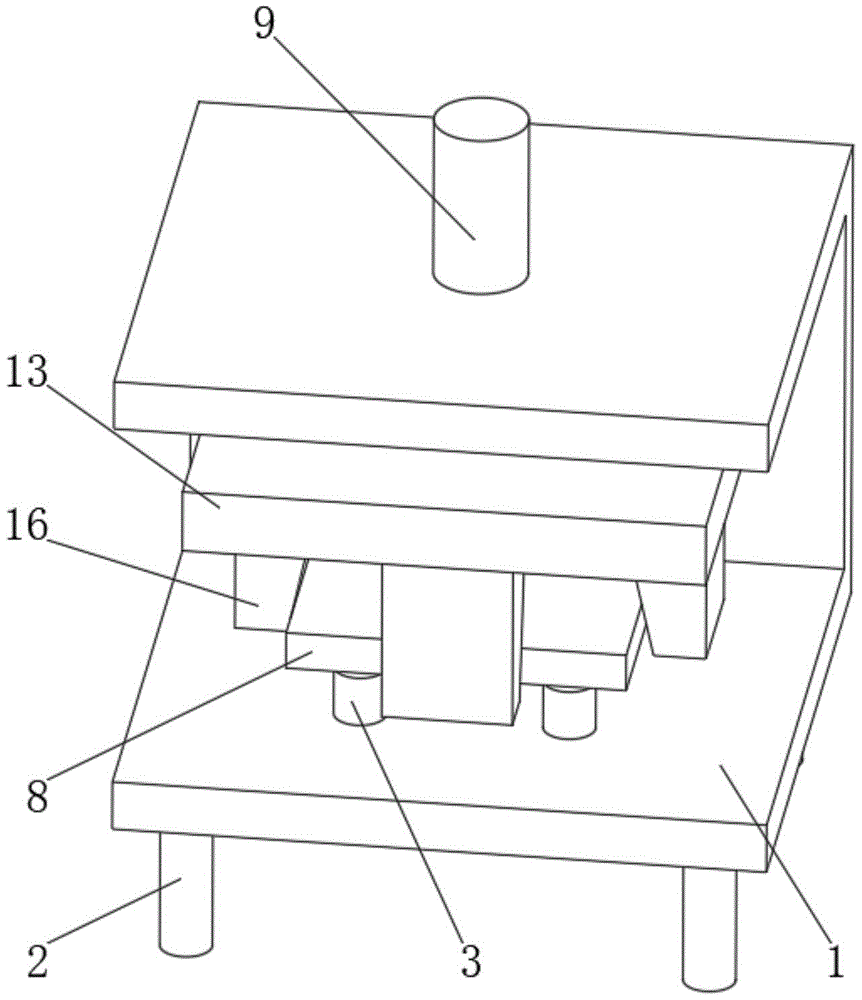
图1为本实用新型整体结构立体图;1 is a perspective view of the overall structure of the present utility model;
图2为本实用新型图1的正视剖视图;Fig. 2 is the front sectional view of Fig. 1 of the utility model;
图3为本实用新型图2中的A处放大图。FIG. 3 is an enlarged view of part A in FIG. 2 of the utility model.
图中:1、框架;2、支脚;3、筒体;4、支柱;5、凸边;6、波纹套;7、磁铁;8、工件;9、气缸;10、气缸杆;11、连接套;12、限位销;13、安装板;14、滑槽;15、滑块;16、斜块;17、导杆;18、弹簧;19、砂轮切割机。In the figure: 1. Frame; 2. Support feet; 3. Cylinder body; 4. Pillar; 5. Raised edge; 6. Corrugated sleeve; 7. Magnet; 8. Workpiece; 9. Cylinder; 10. Cylinder rod; 11. Connection sleeve; 12, limit pin; 13, mounting plate; 14, chute; 15, slider; 16, inclined block; 17, guide rod; 18, spring; 19, grinding wheel cutting machine.
具体实施方式Detailed ways
下面将结合本实用新型实施例中的附图,对本实用新型实施例中的技术方案进行清楚、完整地描述,显然,所描述的实施例仅仅是本实用新型一部分实施例,而不是全部的实施例。基于本实用新型中的实施例,本领域普通技术人员在没有做出创造性劳动前提下所获得的所有其他实施例,都属于本实用新型保护的范围。The technical solutions in the embodiments of the present utility model will be clearly and completely described below with reference to the accompanying drawings in the embodiments of the present utility model. Obviously, the described embodiments are only a part of the embodiments of the present utility model, rather than all the implementations. example. Based on the embodiments of the present invention, all other embodiments obtained by those of ordinary skill in the art without creative work fall within the protection scope of the present invention.
请参阅图1-3,自动纠偏断料机,包括框架1,框架1上焊接有筒体3,筒体3内滑动套接有支柱4,支柱4上焊接有凸边5,凸边5和筒体3滑动连接,筒体3内设置有波纹套6,支柱4上固定安装有磁铁7,磁铁7上吸附有工件8,框架1上固定安装有气缸9,气缸9的气缸杆10和框架1滑动连接,气缸杆10的外侧滑动连接有连接套11,连接套11上焊接有安装板13,安装板13上开设有滑槽14,滑槽14内滑动连接有滑块15,滑块15上焊接有斜块16,滑槽14内焊接有导杆17,导杆17和滑块15滑动连接,导杆17的外侧设置有弹簧18,安装板13上固定安装有砂轮切割机19。Please refer to Figure 1-3, the automatic correcting and cutting machine, including a frame 1, a
请参阅图1,框架1上焊接有四个支脚2,四个支脚2均匀分布在框架1上。通过设置支脚2,对装置进行支撑。Please refer to Figure 1, four
请参阅图3,波纹套6的一端和框架1粘接,波纹套6的另一端和凸边5粘接。通过设置波纹套6,对凸边5进行支撑。Referring to FIG. 3 , one end of the
请参阅图2,连接套11的侧壁滑动套接有限位销12,限位销12和气缸杆10通过螺纹连接。通过设置限位销12,对气缸杆10和连接套11进行连接。Referring to FIG. 2 , the side wall of the connecting
请参阅图2,斜块16和安装板13接触,斜块16和工件8接触。通过设置斜块16,对工件8进行调节。Referring to FIG. 2 , the
请参阅图2,弹簧18的一端和滑块15焊接,弹簧18的另一端和安装板13焊接。通过设置弹簧18,对滑块15进行支撑。Referring to FIG. 2 , one end of the
本实用新型具体实施过程如下:使用时,将工件8放置在磁铁7上,通过磁铁7对工件8进行吸附限位,然后启动气缸9,气缸9启动气缸杆10伸长,气缸杆10伸长带动连接套11移动,连接套11带动安装板13移动,安装板13带动斜块16移动,斜块16移动和工件8接触,在斜块16移动过程中,斜块16下工件8表面滑动,通过设置气缸9、安装板13、滑槽14、滑块15、斜块16、弹簧18等结构,通过弹簧18作用,在气缸9带动斜块16移动,使得斜块16将工件8压紧,并对工件8的位置进行调整纠偏,在此过程中,工件8向下移动,使得磁铁7向下移动,使得支柱4向下移动,使得波纹套6被压缩,通过设置筒体3、支柱4、波纹套6、磁铁7等结构,使得工件8在压紧过程中,对斜块16的压紧力进行缓冲,进而避免工件8被压弯曲,导致工件8切断变形。The specific implementation process of the utility model is as follows: when in use, the
尽管已经示出和描述了本实用新型的实施例,对于本领域的普通技术人员而言,可以理解在不脱离本实用新型的原理和精神的情况下可以对这些实施例进行多种变化、修改、替换和变型,本实用新型的范围由所附权利要求及其等同物限定。Although the embodiments of the present invention have been shown and described, it will be understood by those skilled in the art that various changes and modifications can be made to these embodiments without departing from the principles and spirit of the present invention , alternatives and modifications, the scope of the present invention is defined by the appended claims and their equivalents.
Claims (6)
Priority Applications (1)
| Application Number | Priority Date | Filing Date | Title |
|---|---|---|---|
| CN202123079204.3U CN216327442U (en) | 2021-12-09 | 2021-12-09 | Automatic deviation-rectifying material cutting machine |
Applications Claiming Priority (1)
| Application Number | Priority Date | Filing Date | Title |
|---|---|---|---|
| CN202123079204.3U CN216327442U (en) | 2021-12-09 | 2021-12-09 | Automatic deviation-rectifying material cutting machine |
Publications (1)
| Publication Number | Publication Date |
|---|---|
| CN216327442U true CN216327442U (en) | 2022-04-19 |
Family
ID=81162380
Family Applications (1)
| Application Number | Title | Priority Date | Filing Date |
|---|---|---|---|
| CN202123079204.3U Expired - Fee Related CN216327442U (en) | 2021-12-09 | 2021-12-09 | Automatic deviation-rectifying material cutting machine |
Country Status (1)
| Country | Link |
|---|---|
| CN (1) | CN216327442U (en) |
Cited By (2)
| Publication number | Priority date | Publication date | Assignee | Title |
|---|---|---|---|---|
| CN115958481A (en) * | 2022-10-08 | 2023-04-14 | 青岛欧亚自动化设备有限公司 | Guide rail machining device and method |
| CN116175244A (en) * | 2022-12-15 | 2023-05-30 | 容德精机(江苏)机床有限公司 | Metal sheet processing machine tool with automatic feeding structure |
-
2021
- 2021-12-09 CN CN202123079204.3U patent/CN216327442U/en not_active Expired - Fee Related
Cited By (3)
| Publication number | Priority date | Publication date | Assignee | Title |
|---|---|---|---|---|
| CN115958481A (en) * | 2022-10-08 | 2023-04-14 | 青岛欧亚自动化设备有限公司 | Guide rail machining device and method |
| CN116175244A (en) * | 2022-12-15 | 2023-05-30 | 容德精机(江苏)机床有限公司 | Metal sheet processing machine tool with automatic feeding structure |
| CN116175244B (en) * | 2022-12-15 | 2023-11-03 | 容德精机(江苏)机床有限公司 | Metal sheet processing machine tool with automatic feeding structure |
Similar Documents
| Publication | Publication Date | Title |
|---|---|---|
| CN215745661U (en) | Bending die | |
| CN208067069U (en) | A kind of angle steel eyelet work device | |
| CN109591376A (en) | Bag pad pasting heat seal device | |
| CN205869302U (en) | A double station feeding machine | |
| CN210805938U (en) | A glue sticking device | |
| CN111618160A (en) | A sheet metal blanking die | |
| CN221697993U (en) | Hydraulic press adjusting device for automobile part machining | |
| CN217858172U (en) | Flanging machine is used in production of fan panel | |
| CN207479307U (en) | A kind of mini-type punching perforating mold | |
| CN206356423U (en) | A stamping press with synchronous clamping function | |
| CN213197797U (en) | Film products cutting is with compressing tightly positioning mechanism | |
| CN204123158U (en) | A kind of positioning compression device | |
| CN214392051U (en) | Hardware processing is with entering mould tool fast | |
| CN209759306U (en) | Cell-phone display screen lobe of a leaf device and cell-phone display screen system of processing | |
| CN208772235U (en) | A kind of manipulator rushes waist machine automatically | |
| CN221912271U (en) | Cross beam adjusting structure of grooving machine | |
| CN221790693U (en) | Automatic go up punching press groover of unloading | |
| CN217192887U (en) | Feeding device of plate shearing machine | |
| CN221937633U (en) | Carton flattening die-cutting machine | |
| CN206393754U (en) | A kind of handset touch panel section decompressor | |
| CN221968270U (en) | Circular knife die cutting machine | |
| CN217728904U (en) | A positioning and cutting device for carbon fiber materials | |
| CN221737226U (en) | Cardboard cross cutting machine of carton | |
| CN221734585U (en) | A kind of ultra-thin mechanical parts punching equipment to prevent breakage | |
| CN221658643U (en) | Adjustable clamping device for metal product processing |
Legal Events
| Date | Code | Title | Description |
|---|---|---|---|
| GR01 | Patent grant | ||
| GR01 | Patent grant | ||
| CF01 | Termination of patent right due to non-payment of annual fee |
Granted publication date: 20220419 |
|
| CF01 | Termination of patent right due to non-payment of annual fee |