CN216322893U - Paint spraying room for purifying paint particles in air - Google Patents
Paint spraying room for purifying paint particles in air Download PDFInfo
- Publication number
- CN216322893U CN216322893U CN202122727832.1U CN202122727832U CN216322893U CN 216322893 U CN216322893 U CN 216322893U CN 202122727832 U CN202122727832 U CN 202122727832U CN 216322893 U CN216322893 U CN 216322893U
- Authority
- CN
- China
- Prior art keywords
- center
- spray booth
- paint
- air
- paint spray
- Prior art date
- Legal status (The legal status is an assumption and is not a legal conclusion. Google has not performed a legal analysis and makes no representation as to the accuracy of the status listed.)
- Active
Links
- 239000003973 paint Substances 0.000 title claims abstract description 108
- 239000002245 particle Substances 0.000 title claims abstract description 47
- 238000005507 spraying Methods 0.000 title claims description 20
- 239000007921 spray Substances 0.000 claims abstract description 57
- OKTJSMMVPCPJKN-UHFFFAOYSA-N Carbon Chemical compound [C] OKTJSMMVPCPJKN-UHFFFAOYSA-N 0.000 claims abstract description 37
- 238000000746 purification Methods 0.000 claims abstract description 24
- XLYOFNOQVPJJNP-UHFFFAOYSA-N water Substances O XLYOFNOQVPJJNP-UHFFFAOYSA-N 0.000 claims abstract description 23
- 238000010438 heat treatment Methods 0.000 claims abstract description 21
- 238000001179 sorption measurement Methods 0.000 claims abstract description 19
- 239000007788 liquid Substances 0.000 claims abstract description 9
- 239000011521 glass Substances 0.000 claims abstract description 7
- 239000008187 granular material Substances 0.000 claims description 7
- 239000004922 lacquer Substances 0.000 claims description 6
- 238000009423 ventilation Methods 0.000 claims description 4
- 229910052799 carbon Inorganic materials 0.000 claims 1
- 238000000926 separation method Methods 0.000 abstract description 3
- 239000007864 aqueous solution Substances 0.000 description 6
- 239000007789 gas Substances 0.000 description 6
- 239000010865 sewage Substances 0.000 description 6
- 238000001914 filtration Methods 0.000 description 4
- 239000003595 mist Substances 0.000 description 4
- 239000011248 coating agent Substances 0.000 description 3
- 238000000576 coating method Methods 0.000 description 3
- 238000007599 discharging Methods 0.000 description 3
- 238000000889 atomisation Methods 0.000 description 2
- 239000010815 organic waste Substances 0.000 description 2
- 238000005086 pumping Methods 0.000 description 2
- 230000009286 beneficial effect Effects 0.000 description 1
- 238000004140 cleaning Methods 0.000 description 1
- 230000003749 cleanliness Effects 0.000 description 1
- 238000000034 method Methods 0.000 description 1
- 238000012986 modification Methods 0.000 description 1
- 230000004048 modification Effects 0.000 description 1
- 238000010422 painting Methods 0.000 description 1
- 239000000243 solution Substances 0.000 description 1
- 239000000725 suspension Substances 0.000 description 1
Images
Landscapes
- Details Or Accessories Of Spraying Plant Or Apparatus (AREA)
Abstract
The utility model discloses a paint spray booth for purifying paint particles in air, which comprises a paint spray booth body, wherein a glass window is embedded in the center of the front end of the paint spray booth body, a numerical control panel is installed at one side of the center of the front end of the paint spray booth body, a pretreatment box is fixedly connected with one side of the center of the top of the paint spray booth body, a purification collection box corresponding to the pretreatment box is fixedly connected with the center of one side of the paint spray booth body, and an air collection hopper is fixedly connected with the top of the center of the inner wall of the paint spray booth body. According to the utility model, the purification collection box is arranged on one side of the outer wall of the paint spray booth body and is communicated with the pretreatment box through the automatic liquid discharge pipe, the water solution doped with paint particles in the pretreatment box is filtered in the purification collection box through the bipolar activated carbon adsorption net, and the heating splint and the plurality of annular heat collection pipes can heat the bipolar activated carbon adsorption net to enable the paint particles to fall off, so that the separation efficiency of the paint particles is improved, and the reliability is good.
Description
Technical Field
The utility model relates to the technical field of paint spraying processing, in particular to a paint spraying room for purifying paint particles in air.
Background
The paint spray booth is also called a paint baking booth, is equipment for providing special environment for coating operation, can meet the requirements of coating operation on temperature, humidity, illuminance, air cleanliness and the like, can limit and treat paint mist and organic waste gas generated during the paint spraying operation and then discharge the treated paint mist and organic waste gas, and is environment-friendly coating equipment.
The mode of spraying paint in spray booth has modes such as automatic spraying paint and manual painting, no matter which kind of mode is when carrying out the paint finish spraying, and part paint can form tiny granule and suspension in the air when high-pressure jet, not only can have healthy harm to technical staff, still can have the problem of polluted environment with its direct discharge in the external environment. However, the existing paint spray booth can not purify and separate the suspended paint particles in the air, and when the suspended paint particles generated during the operation of the paint spray booth are doped in the air and are not in time for purification treatment, the paint spraying quality of the subsequent paint spraying processing can be influenced; and the filter screen for purifying and filtering paint particles cannot be subjected to paint particle dragging treatment, so that the paint particle purifying treatment efficiency in subsequent air can be influenced.
It is therefore desirable to provide a paint spray booth that purifies paint particles in the air to solve the above problems.
SUMMERY OF THE UTILITY MODEL
The utility model aims to solve the technical problems that the existing paint spray booth can not purify and separate paint particles suspended in air, and the suspended paint particles generated during the work of the paint spray booth are doped in the air and cannot be purified in time, so that the paint surface spraying quality of the subsequent paint spraying processing can be influenced; and the filter screen for purifying and filtering paint particles cannot be subjected to paint particle dragging treatment, so that the paint particle purifying treatment efficiency in subsequent air can be influenced.
In order to solve the technical problems, the utility model adopts a technical scheme that: the utility model provides a spray booth of lacquer granule in air-purifying, includes the spray booth body, the central gomphosis of spray booth body front end has the glass window, and the operating condition in the spray booth body can be observed to the glass window, numerical control panel is installed to one side at spray booth body front end center, and numerical control panel is used for controlling the beginning and the pause of spray booth body work, one side fixedly connected with preliminary treatment case at spray booth body top center, preliminary treatment case are used for carrying out the preliminary treatment to the lacquer granule in the air, the central fixedly connected with of spray booth body one side with preliminary treatment case corresponding purification collecting box, purification collecting box are used for purifying and filtering the aqueous solution that obtains after the preliminary treatment, the top fixedly connected with collection wind fill at spray booth body inner wall center collects the lacquer granule in the air of spray booth body, the top center of spray booth body outer wall installs high pressure positive blower, the high-pressure fan is used for pumping paint particles in the air in the paint spray booth body into the pretreatment box through the air collecting hopper, the center of the top of the high-pressure fan is fixedly connected with one side of the pretreatment box through a ventilation pipe, and the ventilation pipe is used for conducting the high-pressure fan and the pretreatment box;
the automatic paint spraying device comprises a pretreatment box, a motor, a spiral-flow plate, an automatic liquid discharge pipe and a water storage tank, wherein a water tank is fixedly connected to one side of the center of the top of the pretreatment box and used for storing water, atomizing nozzles are mounted on two sides of the center of the top of the inner wall of the pretreatment box and used for atomizing and spraying water, the motor is mounted at the center of the top of the outer wall of the pretreatment box and used for driving the spiral-flow plate to rotate, the spiral-flow plate is mounted at the output end of the motor and can enable air containing paint particles to be in full contact with water, the bottom of one side of the pretreatment box is fixedly connected with one side of the center of the top of a purification collecting box through the automatic liquid discharge pipe, and the automatic liquid discharge pipe is used for conducting the pretreatment box and the purification collecting box;
purify one side at collecting box top center and install automatic exhaust pipe, automatic exhaust pipe is used for discharging the gas after handling in the purification collecting box, purify the week side at collecting box inner wall center and install the heating splint, the heating splint can carry out heat treatment to bipolar activated carbon adsorption net, heating splint inner wall center fixedly connected with bipolar activated carbon adsorption net, bipolar activated carbon adsorption net can adsorb the lacquer granule and get rid of, purify the central bottom week side fixedly connected with collection filter screen of collecting box inner wall, the collection filter screen collects the lacquer granule that bipolar activated carbon adsorption net drops because of adding, purify the central bottom in collecting box one side and install automatic blow off pipe, automatic blow off pipe is used for discharging the sewage in the purification collecting box.
Preferably, the top at the center of the inner wall of the pretreatment tank is fixedly connected with a hollow balance column sleeve corresponding to the motor, and the hollow balance column sleeve can ensure the stability of the output end of the motor during rotation.
Preferably, the air collecting hopper includes a plurality of air suction nozzles, and the plurality of air suction nozzles can improve the efficiency of pumping air.
Preferably, the water tank and the two atomizing nozzles are fixedly connected through rubber hoses.
Preferably, the rotational flow plate is rotatably connected with the inner wall of the pretreatment tank.
Preferably, the heating clamping plate comprises a plurality of annular heat collecting pipes.
Preferably, a plurality of annular heat collecting pipes are uniformly embedded in the center of the inner wall of the heating clamping plate, and the plurality of annular heat collecting pipes can enable the bipolar activated carbon adsorption net to be heated up quickly.
The utility model has the following beneficial effects:
1. according to the utility model, the high-pressure fan and the air collecting hopper are arranged at the center of the top of the paint spray booth body, the paint spray booth is connected with the pretreatment tank through the ventilation pipe, paint particles generated by the paint spray booth body are doped in the air and pumped into the pretreatment tank, and the paint particles are fully contacted with water and settled under the action of the water tank, the two atomizing nozzles and the rotational flow plate, so that the paint particles are well doped in an aqueous solution, and the subsequent purification and separation of the paint particles are effectively pretreated;
2. according to the utility model, the purification collection box is arranged on one side of the outer wall of the paint spray booth body and is communicated with the pretreatment box through the automatic liquid discharge pipe, the water solution doped with paint particles in the pretreatment box is filtered in the purification collection box through the bipolar activated carbon adsorption net, and the heating splint and the plurality of annular heat collection pipes can heat the bipolar activated carbon adsorption net to enable the paint particles to fall off, so that the separation efficiency of the paint particles is improved, and the reliability is good;
3. according to the utility model, the automatic exhaust pipe, the filter screen and the automatic blow-off pipe are arranged in the purification collection box, paint particles which are heated from the bipolar activated carbon adsorption net and fall off fall onto the filter screen for centralized collection, and the generated clean gas is discharged from the automatic exhaust pipe, so that the paint particles in the air are effectively purified and separated, and the energy-saving and environment-friendly performance is stronger.
Drawings
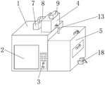
FIG. 1 is a perspective view of the present invention;
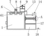
FIG. 2 is a front sectional view of the present invention;
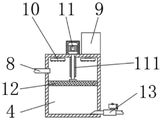
FIG. 3 is an enlarged view of the structure of the pretreatment tank of the present invention;
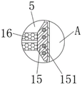
fig. 4 is a partially enlarged view of a portion a in fig. 2.
In the figure: 1. a paint spray booth body; 2. a glass window; 3. a numerical control panel; 4. a pretreatment tank; 5. a purifying and collecting box; 6. a wind collecting hopper; 61. a suction nozzle; 7. a high pressure fan; 8. a vent pipe; 9. a water tank; 10. an atomizing spray head; 11. a motor; 111. a hollow balance column sleeve; 12. a swirl plate; 13. an automatic drain pipe; 14. an automatic exhaust duct; 15. heating the clamping plate; 151. an annular heat collecting pipe; 16. a bipolar activated carbon adsorption net; 17. a filter screen is collected; 18. an automatic sewage draining pipe.
Detailed Description
The following detailed description of the preferred embodiments of the present invention, taken in conjunction with the accompanying drawings, will make the advantages and features of the utility model easier to understand by those skilled in the art, and thus will clearly and clearly define the scope of the utility model.
Referring to fig. 1 and 2, a paint spray booth for purifying paint particles in air includes a paint spray booth body 1, a glass window 2 is embedded in the center of the front end of the paint spray booth body 1, the glass window 2 can observe the working condition inside the paint spray booth body 1, a numerical control panel 3 is installed on one side of the center of the front end of the paint spray booth body 1, the numerical control panel 3 is used for controlling the start and stop of the operation of the paint spray booth body 1, a pretreatment tank 4 is fixedly connected to one side of the center of the top of the paint spray booth body 1, the pretreatment tank 4 is used for pretreating paint particles in air, a hollow balance column sleeve 111 corresponding to a motor 11 is fixedly connected to the top of the center of the inner wall of the pretreatment tank 4, the hollow balance column sleeve 111 can ensure the stability of the rotation of the output end of the motor 11, a purification collection box 5 corresponding to the pretreatment tank 4 is fixedly connected to the center of one side of the paint spray booth body 1, the purification and collection box 5 is used for purifying and filtering the aqueous solution obtained after the pretreatment, the top of the center of the inner wall of the spray booth body 1 is fixedly connected with an air collection hopper 6, the air collection hopper 6 is used for collecting paint particles in the air inside the spray booth body 1, the air collection hopper 6 comprises a plurality of air suction nozzles 61, the plurality of air suction nozzles 61 can improve the air suction efficiency, a high pressure fan 7 is installed at the top center of the outer wall of the spray booth body 1, the high pressure fan 7 is used for sucking the paint particles in the air inside the spray booth body 1 into the pretreatment box 4 through the air collection hopper 6, the top center of the high pressure fan 7 is fixedly connected with one side of the pretreatment box 4 through a vent pipe 8, the vent pipe 8 is used for conducting the high pressure fan 7 and the pretreatment box 4, an automatic exhaust pipe 14 is installed at one side of the top center of the purification and collection box 5, the automatic exhaust pipe 14 is used for exhausting the gas after the purification and collection box 5 is treated, a collecting filter screen 17 is fixedly connected to the periphery of the bottom of the center of the inner wall of the purifying and collecting box 5, paint particles falling off due to the addition of the bipolar activated carbon adsorption screen 16 are collected by the collecting filter screen 17, an automatic sewage discharge pipe 18 is installed at the bottom of the center of one side of the purifying and collecting box 5, and the automatic sewage discharge pipe 18 is used for discharging sewage in the purifying and collecting box 5;
referring to fig. 3, a water tank 9 is fixedly connected to one side of the center of the top of the pretreatment tank 4, the water tank 9 is used for storing water, the water tank 9 and the two atomizing nozzles 10 are fixedly connected through rubber hoses, the atomizing nozzles 10 are mounted on two sides of the center of the top of the inner wall of the pretreatment tank 4, the atomizing nozzles 10 are used for atomizing and spraying water, a motor 11 is mounted at the center of the top of the outer wall of the pretreatment tank 4, the motor 11 is used for driving a rotational flow plate 12 to rotate, the rotational flow plate 12 is mounted at the output end of the motor 11, the rotational flow plate 12 can enable air containing paint particles to be in full contact with water, the rotational flow plate 12 is rotatably connected with the inner wall of the pretreatment tank 4, the bottom of one side of the pretreatment tank 4 is fixedly connected with one side of the center of the top of the purification collection tank 5 through an automatic liquid discharge pipe 13, and the automatic liquid discharge pipe 13 is used for conducting the pretreatment tank 4 and the purification collection tank 5;
referring to fig. 4, a heating clamp plate 15 is installed on the periphery of the center of the inner wall of the purification collection box 5, the heating clamp plate 15 can heat the bipolar activated carbon adsorption net 16, the heating clamp plate 15 includes a plurality of annular heat collecting tubes 151, the plurality of annular heat collecting tubes 151 are evenly embedded in the center of the inner wall of the heating clamp plate 15, the plurality of annular heat collecting tubes 151 can enable the bipolar activated carbon adsorption net 16 to rapidly heat up, the center of the inner wall of the heating clamp plate 15 is fixedly connected with the bipolar activated carbon adsorption net 16, and the bipolar activated carbon adsorption net 16 can adsorb and remove paint particles.
When the utility model is used, when the paint surface spraying processing is carried out in a paint spraying room body 1, the generated paint particles are doped in the air, the air is pumped into a pretreatment tank 4 through a vent pipe 8 by an air collecting hopper 6 and a plurality of air suction nozzles 61 under the action of a high pressure fan 7, a water tank 9 carries out atomization and water spraying through two atomization nozzles 10, a motor 11 is started simultaneously to drive a rotational flow plate 12 to start rotating, so that water mist can be fully contacted with the air doped with the paint particles, then the water mist is settled and doped in an aqueous solution, the aqueous solution is discharged into a purification and collection tank 5 through an automatic liquid discharge pipe 13, the paint particles are filtered and separated through a bipolar activated carbon adsorption net 16, the aqueous solution after the paint particles are separated is discharged through an automatic sewage discharge pipe 18, the bipolar activated carbon adsorption net 16 raises the temperature under the heating action of a heating clamping plate 15 and a plurality of annular heat collection pipes 151, and further the paint particles fall off, and falls to the filter screen 17 for collection and treatment, and is convenient for cleaning in the later period, and the gas generated in the heating process is discharged from the external environment of the automatic exhaust pipe 14.
The above description is only an embodiment of the present invention, and not intended to limit the scope of the present invention, and all modifications of equivalent structures and equivalent processes performed by the present specification and drawings, or directly or indirectly applied to other related technical fields, are included in the scope of the present invention.
Claims (7)
1. The utility model provides a paint spraying booth of lacquer granule in air-purifying, includes paint spraying booth body (1), its characterized in that: the glass window (2) is embedded in the center of the front end of the paint spray booth body (1), a numerical control panel (3) is installed on one side of the center of the front end of the paint spray booth body (1), a pretreatment box (4) is fixedly connected to one side of the center of the top of the paint spray booth body (1), a purification and collection box (5) corresponding to the pretreatment box (4) is fixedly connected to the center of one side of the paint spray booth body (1), an air collection hopper (6) is fixedly connected to the top of the center of the inner wall of the paint spray booth body (1), a high-pressure fan (7) is installed at the center of the top of the outer wall of the paint spray booth body (1), and the center of the top of the high-pressure fan (7) is fixedly connected with one side of the pretreatment box (4) through a ventilation pipe (8);
a water tank (9) is fixedly connected to one side of the center of the top of the pretreatment tank (4), atomizing nozzles (10) are mounted on two sides of the center of the top of the inner wall of the pretreatment tank (4), a motor (11) is mounted at the center of the top of the outer wall of the pretreatment tank (4), a rotational flow plate (12) is mounted at the output end of the motor (11), and the bottom of one side of the pretreatment tank (4) is fixedly connected with one side of the center of the top of the purification and collection tank (5) through an automatic liquid discharge pipe (13);
purify one side at collecting box (5) top center and install automatic exhaust pipe (14), purify week side at collecting box (5) inner wall center and install heating splint (15), heating splint (15) inner wall center fixedly connected with bipolar active carbon adsorption net (16), purify bottom week side fixedly connected with collection filter screen (17) at collecting box (5) inner wall center, purify the bottom at collecting box (5) one side center and install automatic blow off pipe (18).
2. The paint spray booth for purifying paint particles in air of claim 1, wherein: the top of the center of the inner wall of the pretreatment box (4) is fixedly connected with a hollow balance column sleeve (111) corresponding to the motor (11).
3. The paint spray booth for purifying paint particles in air of claim 1, wherein: the air collecting hopper (6) comprises a plurality of air suction nozzles (61).
4. The paint spray booth for purifying paint particles in air of claim 1, wherein: the water tank (9) and the two atomizing nozzles (10) are fixedly connected through rubber hoses.
5. The paint spray booth for purifying paint particles in air of claim 1, wherein: the rotational flow plate (12) is rotationally connected with the inner wall of the pretreatment tank (4).
6. The paint spray booth for purifying paint particles in air of claim 1, wherein: the heating clamping plate (15) comprises a plurality of annular heat collecting pipes (151).
7. The paint spray booth for purifying paint particles in air of claim 1, wherein: a plurality of annular heat collecting pipes (151) are uniformly embedded in the center of the inner wall of the heating clamping plate (15).
Priority Applications (1)
| Application Number | Priority Date | Filing Date | Title |
|---|---|---|---|
| CN202122727832.1U CN216322893U (en) | 2021-11-09 | 2021-11-09 | Paint spraying room for purifying paint particles in air |
Applications Claiming Priority (1)
| Application Number | Priority Date | Filing Date | Title |
|---|---|---|---|
| CN202122727832.1U CN216322893U (en) | 2021-11-09 | 2021-11-09 | Paint spraying room for purifying paint particles in air |
Publications (1)
| Publication Number | Publication Date |
|---|---|
| CN216322893U true CN216322893U (en) | 2022-04-19 |
Family
ID=81137714
Family Applications (1)
| Application Number | Title | Priority Date | Filing Date |
|---|---|---|---|
| CN202122727832.1U Active CN216322893U (en) | 2021-11-09 | 2021-11-09 | Paint spraying room for purifying paint particles in air |
Country Status (1)
| Country | Link |
|---|---|
| CN (1) | CN216322893U (en) |
Cited By (1)
| Publication number | Priority date | Publication date | Assignee | Title |
|---|---|---|---|---|
| CN116764861A (en) * | 2023-06-13 | 2023-09-19 | 江苏齐力涂装机械制造有限公司 | Air purification device for spray booth |
-
2021
- 2021-11-09 CN CN202122727832.1U patent/CN216322893U/en active Active
Cited By (1)
| Publication number | Priority date | Publication date | Assignee | Title |
|---|---|---|---|---|
| CN116764861A (en) * | 2023-06-13 | 2023-09-19 | 江苏齐力涂装机械制造有限公司 | Air purification device for spray booth |
Similar Documents
| Publication | Publication Date | Title |
|---|---|---|
| CN116078151B (en) | Automatic change spraying line exhaust treatment device | |
| CN218221658U (en) | Air purification atomizing device | |
| CN216894498U (en) | A spray dust collector for mine operation | |
| CN111991987A (en) | Inside of industrial waste gas discharge pipeline adsorbs automatically cleaning equipment | |
| CN209985137U (en) | Dye waste gas purification treatment device | |
| CN112370949A (en) | Industrial waste gas high concentration acid mist purifying tower | |
| CN215427948U (en) | Air dust removal and purification device for textile workshop | |
| CN212881767U (en) | Efficient oil smoke purifier | |
| CN221788613U (en) | VOC waste gas purifying treatment device with self-cleaning function | |
| CN214513576U (en) | Multistage filter equipment is used in exhaust-gas treatment for chemical plant | |
| CN215085812U (en) | Spray tower for exhaust-gas treatment | |
| CN109939529B (en) | A paint slag drying waste gas treatment device | |
| CN214864694U (en) | High-efficient environment-friendly spray booth | |
| CN213732778U (en) | Waste gas purification device for heating in plastic production | |
| CN214487515U (en) | Building energy-saving environment-friendly paint spraying device | |
| CN212819010U (en) | Deodorization device of integrated sewage treatment equipment | |
| CN210584397U (en) | Electric automatization environmental protection dust collector | |
| CN212999050U (en) | Spray treatment device of vertical waste gas washing tower | |
| CN211274044U (en) | High-efficiency industrial smoke energy-saving purification device | |
| CN219615192U (en) | Dust remover | |
| CN219682109U (en) | Multi-level filtering and purifying device | |
| CN220083142U (en) | Energy-saving electrostatic fume purifying equipment | |
| CN208878192U (en) | A high-efficiency dust-removing spray tower | |
| CN220397739U (en) | Strong air suction type air exhaust and ventilation structure | |
| CN218077165U (en) | Waste gas absorption tower with cleaning function for sludge treatment |
Legal Events
| Date | Code | Title | Description |
|---|---|---|---|
| GR01 | Patent grant | ||
| GR01 | Patent grant |