CN216299615U - Mould for casting composite wallboard - Google Patents
Mould for casting composite wallboard Download PDFInfo
- Publication number
- CN216299615U CN216299615U CN202122578988.8U CN202122578988U CN216299615U CN 216299615 U CN216299615 U CN 216299615U CN 202122578988 U CN202122578988 U CN 202122578988U CN 216299615 U CN216299615 U CN 216299615U
- Authority
- CN
- China
- Prior art keywords
- bayonet
- plate bayonet
- side plate
- groove
- casting
- Prior art date
- Legal status (The legal status is an assumption and is not a legal conclusion. Google has not performed a legal analysis and makes no representation as to the accuracy of the status listed.)
- Expired - Fee Related
Links
- 239000002131 composite material Substances 0.000 title claims abstract description 41
- 238000005266 casting Methods 0.000 title claims abstract description 17
- 238000004519 manufacturing process Methods 0.000 claims abstract description 11
- 241000446313 Lamella Species 0.000 abstract description 10
- 238000012999 compression bending Methods 0.000 abstract 1
- 238000005452 bending Methods 0.000 description 3
- 230000006835 compression Effects 0.000 description 3
- 238000007906 compression Methods 0.000 description 3
- 238000000034 method Methods 0.000 description 3
- 230000007547 defect Effects 0.000 description 2
- 238000001125 extrusion Methods 0.000 description 2
- 238000005242 forging Methods 0.000 description 2
- 239000000243 solution Substances 0.000 description 2
- 238000003723 Smelting Methods 0.000 description 1
- 230000009286 beneficial effect Effects 0.000 description 1
- 239000000919 ceramic Substances 0.000 description 1
- 238000000748 compression moulding Methods 0.000 description 1
- 238000005520 cutting process Methods 0.000 description 1
- 238000004512 die casting Methods 0.000 description 1
- 229920006351 engineering plastic Polymers 0.000 description 1
- 238000005516 engineering process Methods 0.000 description 1
- 238000009776 industrial production Methods 0.000 description 1
- 238000002347 injection Methods 0.000 description 1
- 239000007924 injection Substances 0.000 description 1
- 238000001746 injection moulding Methods 0.000 description 1
- 239000000463 material Substances 0.000 description 1
- 230000004048 modification Effects 0.000 description 1
- 238000012986 modification Methods 0.000 description 1
- 238000004663 powder metallurgy Methods 0.000 description 1
- 238000003825 pressing Methods 0.000 description 1
- 239000005060 rubber Substances 0.000 description 1
- 230000003746 surface roughness Effects 0.000 description 1
Images


Landscapes
- Finishing Walls (AREA)
Abstract
The utility model discloses a mold for producing and casting a composite wallboard, which comprises a mold body, wherein one side of the mold body is provided with a first side plate bayonet, the other side of the mold body is provided with a second side plate bayonet, one side of the mold body is provided with a groove, one side of the groove is provided with a first middle plate bayonet, the other side of the mold body is provided with a convex groove, one side of the convex groove is provided with a second middle plate bayonet, the two first side plate bayonets are symmetrically distributed by using the central line of the mold body, and the two second side plate bayonets are symmetrically distributed by using the central line of the mold body; this mould is used in composite wall panel production casting can reach and to make the structural strength of composite wall panel after producing high, the better purpose of resistance to compression bending performance through being provided with mould body, first sideboard bayonet socket, second sideboard bayonet socket, recess, first intermediate lamella bayonet socket, tongue and second intermediate lamella bayonet socket.
Description
Technical Field
The utility model relates to the technical field of composite wallboard molds, in particular to a mold for casting composite wallboard.
Background
Dies, various moulds and tools for obtaining the desired products by injection, blow, extrusion, die-casting or forging, smelting, stamping, etc. in industrial production, in short, a die is a tool for making shaped articles, which tool is composed of various parts, and different dies are composed of different parts. The method realizes the processing of the shape of an article mainly by changing the physical state of a formed material, and enables a blank to be a tool of a workpiece with a specific shape and size under the action of external force. The method is widely applied to blanking, die forging, cold heading, extrusion, powder metallurgy part pressing, pressure casting and the forming processing of compression molding or injection molding of products such as engineering plastics, rubber, ceramics and the like. The mould has a specific contour or inner cavity shape, and the blank can be separated according to the contour shape by applying the contour shape with the cutting edge. The blank can obtain a corresponding three-dimensional shape by using the shape of the inner cavity, and the die generally comprises a movable die and a fixed die which can be separated and combined, a workpiece is taken out when the movable die and the fixed die are separated, and the blank is injected into a die cavity for forming when the movable die and the fixed die are combined. The die is a precise tool, has a complex shape, bears the expansion force of a blank, has higher requirements on structural strength, rigidity, surface hardness, surface roughness and processing precision, and needs to be poured and fixed by the die in the production process of the composite wallboard.
The prior art has the following defects or problems:
1. the existing mould for producing the composite wallboard is single in structure, and the wallboard produced by using the existing mould product is low in structural strength and poor in compression resistance and bending resistance.
SUMMERY OF THE UTILITY MODEL
The utility model aims to provide a mould for producing and casting a composite wallboard aiming at the defects in the prior art so as to solve the problems in the background technology.
In order to achieve the purpose, the utility model provides the following technical scheme: the utility model provides a mould is used in casting of composite wall panel production, includes the mould body, one side of mould body is provided with first sideboard bayonet socket, the opposite side of mould body is provided with second sideboard bayonet socket, one side of mould body is provided with the recess, one side of recess is provided with first intermediate lamella bayonet socket, the opposite side of mould body is provided with the tongue, one side of tongue is provided with second intermediate lamella bayonet socket.
As a preferred technical scheme of the present invention, the first side plate bayonets are provided with two side plates and symmetrically distributed with respect to a center line of the mold body, and the second side plate bayonets are provided with two side plates and symmetrically distributed with respect to the center line of the mold body.
As a preferable technical solution of the present invention, the first side plate bayonet and the second side plate bayonet have the same specification and size, and the first side plate bayonet and the second side plate bayonet are located in the same horizontal plane.
As a preferable technical scheme of the present invention, the first middle plate bayonet is provided with two and symmetrically distributed with a center line of the groove, and a bottom end of the first middle plate bayonet is fixedly connected with one side of the groove.
As a preferable technical scheme of the utility model, the second middle plate bayonets are provided with two bayonets which are symmetrically distributed by using the center line of the convex groove, and the bottom ends of the second middle plate bayonets are fixedly connected with one side of the convex groove.
As a preferable aspect of the present invention, the first intermediate plate mount and the second intermediate plate mount have the same dimensions, and the first intermediate plate mount and the second intermediate plate mount are located on the same horizontal plane.
Compared with the prior art, the utility model provides a mould for producing and casting a composite wallboard, which has the following beneficial effects:
1. the mould for producing and casting the composite wallboard is provided with a mould body, a first side plate bayonet, a second side plate bayonet, a groove, a first middle plate bayonet, a convex groove and a second middle plate bayonet, wherein when the mould body is used for producing the composite wallboard, the mould body is respectively and independently provided with four blocks which are assembled and fixed in a shape like a Chinese character 'shan', one side of the composite wallboard can be meshed and fixed with the first middle plate bayonet in the first side plate bayonet and the groove, the first middle plate bayonet can be clamped into the composite wallboard, the other side of the composite wallboard can be meshed and fixed with the second middle plate bayonet on the second side plate bayonet and the convex groove, the second middle plate bayonet can be clamped into the composite wallboard, so that the composite wallboard is divided into two parts, and the structural strength of the composite wallboard after production is high due to the arrangement of the mould body in the middle, the compression resistance and bending resistance are better.
Drawings
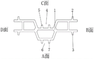
FIG. 1 is a schematic cross-sectional view of a die body of the present invention;
FIG. 2 is a view of the plane A of FIG. 1 in accordance with the present invention;
FIG. 3 is a view of side B of FIG. 1 in accordance with the present invention;
FIG. 4 is a view of the plane C of FIG. 1 in accordance with the present invention;
FIG. 5 is a view taken from plane D of FIG. 1 in accordance with the present invention;
FIG. 6 is a perspective view of FIG. 1 of the present invention (with side A and side B visible);
FIG. 7 is a perspective view of the present invention shown in FIG. 1 (with the C and D surfaces visible);
FIG. 8 is a schematic view of the assembled die body of the present invention.
In the figure: 1. a mold body; 2. a first side plate bayonet; 3. a second side plate bayonet; 4. a groove; 5. a first middle plate bayonet; 6. a convex groove; 7. and a second intermediate plate bayonet.
Detailed Description
The technical solutions in the embodiments of the present invention will be clearly and completely described below with reference to the drawings in the embodiments of the present invention, and it is obvious that the described embodiments are only a part of the embodiments of the present invention, and not all of the embodiments. All other embodiments, which can be derived by a person skilled in the art from the embodiments given herein without making any creative effort, shall fall within the protection scope of the present invention.
Referring to fig. 1-8, in this embodiment: the utility model provides a mould is used in casting of composite wall panel production, includes mould body 1, and one side of mould body 1 is provided with first sideboard bayonet socket 2, and the opposite side of mould body 1 is provided with second sideboard bayonet socket 3, and one side of mould body 1 is provided with recess 4, and one side of recess 4 is provided with first intermediate lamella bayonet socket 5, and the opposite side of mould body 1 is provided with tongue 6, and one side of tongue 6 is provided with second intermediate lamella bayonet socket 7.
In the embodiment, the first side plate bayonet 2 is provided with two side plate bayonets which are symmetrically distributed with the central line of the die body 1, the second side plate bayonet 3 is provided with two side plate bayonets which are symmetrically distributed with the central line of the die body 1, and the first side plate bayonet 2 and the second side plate bayonet 3 can fix the composite wall plate; the first side plate bayonet 2 and the second side plate bayonet 3 are the same in specification and size, and the first side plate bayonet 2 and the second side plate bayonet 3 are located in the same horizontal plane, so that two sides of the composite wallboard can be conveniently fixed; the two first middle plate bayonets 5 are symmetrically distributed along the center line of the groove 4, the bottom end of each first middle plate bayonet 5 is fixedly connected with one side of the groove 4, and the first middle plate bayonets 5 can be clamped into one side of the composite wallboard to strengthen the fixation of the composite wallboard; the two second middle plate bayonets 7 are symmetrically distributed along the center line of the convex groove 6, the bottom end of each second middle plate bayonet 7 is fixedly connected with one side of the convex groove 6, and the second middle plate bayonet 7 can be clamped into one side of the composite wallboard to strengthen the fixation of the composite wallboard; the first middle plate bayonet 5 and the second middle plate bayonet 7 are the same in specification and size, and the first middle plate bayonet 5 and the second middle plate bayonet 7 are located in the same horizontal plane, so that the produced composite wall boards are consistent in specification and shape.
The working principle and the using process of the utility model are as follows: mould body 1 is when producing composite wall panel, mould body 1 independently is provided with four respectively, and it is fixed to be "mountain" style of calligraphy equipment, one side of composite wall panel can mesh fixedly with first intermediate lamella bayonet socket 5 department in first side board bayonet socket 2 and the recess 4, first intermediate lamella bayonet socket 5 can be blocked in advancing composite wall panel, and composite wall panel's opposite side can mesh fixedly with second intermediate lamella bayonet socket 7 on second side board bayonet socket 3 and the tongue 6, and second intermediate lamella bayonet socket 7 can block in advancing composite wall panel, make composite wall panel be divided into two parts, owing to be provided with the structural strength that is located middle mould body 1 can make composite wall panel after producing high, the resistance to compression and bending is better.
Finally, it should be noted that: although the present invention has been described in detail with reference to the foregoing embodiments, it will be apparent to those skilled in the art that changes may be made in the embodiments and/or equivalents thereof without departing from the spirit and scope of the utility model. Any modification, equivalent replacement, or improvement made within the spirit and principle of the present invention should be included in the protection scope of the present invention.
Claims (6)
1. The utility model provides a mould is used in casting of composite wall panel production which characterized in that: the die comprises a die body (1), wherein one side of the die body (1) is provided with a first side plate bayonet (2), the other side of the die body (1) is provided with a second side plate bayonet (3), one side of the die body (1) is provided with a groove (4), one side of the groove (4) is provided with a first middle plate bayonet (5), the other side of the die body (1) is provided with a convex groove (6), and one side of the convex groove (6) is provided with a second middle plate bayonet (7).
2. The mold for casting in composite wallboard production according to claim 1, wherein: the first side plate bayonet (2) is provided with two symmetrical distribution of the central line of the die body (1), and the second side plate bayonet (3) is provided with two symmetrical distribution of the central line of the die body (1).
3. The mold for casting in composite wallboard production according to claim 1, wherein: the first side plate bayonet (2) and the second side plate bayonet (3) are the same in specification and size, and the first side plate bayonet (2) and the second side plate bayonet (3) are located in the same horizontal plane.
4. The mold for casting in composite wallboard production according to claim 1, wherein: the first middle plate bayonet (5) is provided with two and is symmetrically distributed with the central line of groove (4), the bottom of first middle plate bayonet (5) is fixedly connected with one side of groove (4).
5. The mold for casting in composite wallboard production according to claim 1, wherein: the second middle plate bayonet (7) is provided with two central lines which are symmetrically distributed with the convex groove (6), and the bottom end of the second middle plate bayonet (7) is fixedly connected with one side of the convex groove (6).
6. The mold for casting in composite wallboard production according to claim 1, wherein: the first intermediate plate bayonet (5) and the second intermediate plate bayonet (7) are identical in specification and size, and the first intermediate plate bayonet (5) and the second intermediate plate bayonet (7) are located on the same horizontal plane.
Priority Applications (1)
| Application Number | Priority Date | Filing Date | Title |
|---|---|---|---|
| CN202122578988.8U CN216299615U (en) | 2021-10-26 | 2021-10-26 | Mould for casting composite wallboard |
Applications Claiming Priority (1)
| Application Number | Priority Date | Filing Date | Title |
|---|---|---|---|
| CN202122578988.8U CN216299615U (en) | 2021-10-26 | 2021-10-26 | Mould for casting composite wallboard |
Publications (1)
| Publication Number | Publication Date |
|---|---|
| CN216299615U true CN216299615U (en) | 2022-04-15 |
Family
ID=81117043
Family Applications (1)
| Application Number | Title | Priority Date | Filing Date |
|---|---|---|---|
| CN202122578988.8U Expired - Fee Related CN216299615U (en) | 2021-10-26 | 2021-10-26 | Mould for casting composite wallboard |
Country Status (1)
| Country | Link |
|---|---|
| CN (1) | CN216299615U (en) |
-
2021
- 2021-10-26 CN CN202122578988.8U patent/CN216299615U/en not_active Expired - Fee Related
Similar Documents
| Publication | Publication Date | Title |
|---|---|---|
| CN204953630U (en) | Ejecting formula blanking die | |
| CN205997274U (en) | A plastic mold for in-ear earphone earmuffs | |
| CN210358845U (en) | Adjustable section difference combined die for aluminum plate curtain wall decorative corrugated line | |
| CN204638848U (en) | A kind of high accuracy blanking die | |
| CN210589671U (en) | Stamping die for plastic product processing | |
| CN211662451U (en) | Mold ejection system | |
| CN211027563U (en) | 5G is switching support frame aluminium alloy extrusion die for basic station | |
| CN206677022U (en) | A kind of anti-deformation cover rolling fetal membrane | |
| CN214562265U (en) | Washing machine plastic part processing mold replacing device | |
| CN209955378U (en) | Mold blank top forming device for complex mold | |
| CN214161124U (en) | A outer mould for producing environmental protection equipment | |
| CN218224505U (en) | Shell forming die with thick bottom and thin edge | |
| CN216478199U (en) | Fixing seat mold structure | |
| CN217257631U (en) | A mould for plastics processing | |
| CN205702100U (en) | A solar bracket mold | |
| CN214872321U (en) | An injection mold with anti-loosening mechanism | |
| CN213816714U (en) | A portable insert type contact pair reed die | |
| CN205763307U (en) | A kind of television support bearing plate mold | |
| CN210059714U (en) | Die for producing cutting box | |
| CN219464688U (en) | Cavity strip for preparing high-sealing metal part | |
| CN205702101U (en) | A radiator shell mold | |
| CN212917294U (en) | Special abnormal shape haver bulging die utensil | |
| CN214395233U (en) | Front mould inclined core-pulling structure with buffer structure | |
| CN215965881U (en) | Complex composite die with roll core structure | |
| CN207175760U (en) | A kind of mould for being used to produce 3D bend glass cover plates |
Legal Events
| Date | Code | Title | Description |
|---|---|---|---|
| GR01 | Patent grant | ||
| GR01 | Patent grant | ||
| CF01 | Termination of patent right due to non-payment of annual fee |
Granted publication date: 20220415 |
|
| CF01 | Termination of patent right due to non-payment of annual fee |