CN216293367U - Auxiliary device for computer software design - Google Patents
Auxiliary device for computer software design Download PDFInfo
- Publication number
- CN216293367U CN216293367U CN202122796440.0U CN202122796440U CN216293367U CN 216293367 U CN216293367 U CN 216293367U CN 202122796440 U CN202122796440 U CN 202122796440U CN 216293367 U CN216293367 U CN 216293367U
- Authority
- CN
- China
- Prior art keywords
- fixedly installed
- rod
- plate
- auxiliary platform
- computer software
- Prior art date
- Legal status (The legal status is an assumption and is not a legal conclusion. Google has not performed a legal analysis and makes no representation as to the accuracy of the status listed.)
- Expired - Fee Related
Links
Images


Landscapes
- Tables And Desks Characterized By Structural Shape (AREA)
Abstract
本实用新型公开了一种计算机软件设计用辅助装置,包括固定安装在底板上的电动伸缩杆,所述电动伸缩杆上固定安装有辅助平台,所述辅助平台上通过转动杆转动安装有放置板,且放置板与辅助平台之间安装有支撑机构,所述放置板上安装有多个定位机构,所述辅助平台上通过多个支撑弹簧固定安装有绘制板,所述辅助平台上通过转辊转动安装有传动齿轮,所述绘制板上固定安装有阻尼转轴,且阻尼转轴上固定安装有与传动齿轮相啮合的升降齿杆,所述转辊与辅助平台之间安装有固定机构。优点在于:本实用新型能够灵活的调整对照文件的放置位置与角度,从而便于绘图时的观察对照,并可灵活的调整绘制板的高度与角度,使设计人员可快速绘制,较为方便。
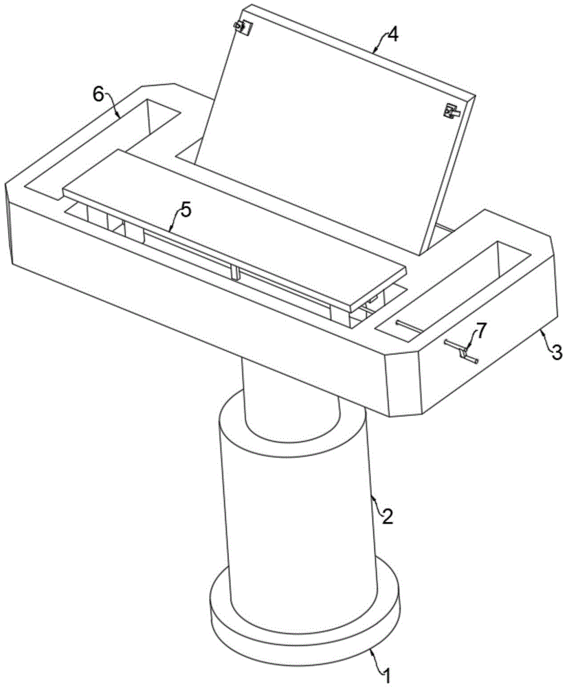
The utility model discloses an auxiliary device for computer software design. , and a supporting mechanism is installed between the placing plate and the auxiliary platform, a plurality of positioning mechanisms are installed on the placing plate, a drawing plate is fixedly installed on the auxiliary platform through a plurality of supporting springs, and the auxiliary platform is installed through a rotating roller A transmission gear is rotatably installed, a damping rotating shaft is fixedly installed on the drawing board, and a lifting gear rod meshing with the transmission gear is fixedly installed on the damping rotating shaft, and a fixing mechanism is installed between the rotating roller and the auxiliary platform. The advantages are: the utility model can flexibly adjust the placement position and angle of the reference file, thereby facilitating observation and comparison during drawing, and can flexibly adjust the height and angle of the drawing board, enabling designers to draw quickly and conveniently.
Description
技术领域technical field
本实用新型涉及计算机软件设计的技术领域,尤其涉及一种计算机软件设计用辅助装置。The utility model relates to the technical field of computer software design, in particular to an auxiliary device for computer software design.
背景技术Background technique
计算机软件是指可在计算机上运行、执行命令的程序集合体,计算机软件在进行设计时,通常需要在辅助装置上进行草图的辅助绘制,以此来提高软件设计的准确度;Computer software refers to a collection of programs that can run and execute commands on a computer. When designing computer software, it is usually necessary to draw sketches on auxiliary devices to improve the accuracy of software design;
现有辅助装置仅采用桌体或板体构成,结构与功能均较为简单,设计人员在进行绘图时,不仅无法便捷的进行观察对照,也无法灵活的调整绘图的高度与角度,使用较为麻烦,具有一定的局限性,因此亟需设计一种计算机软件设计用辅助装置来解决上述问题。The existing auxiliary device is only composed of a table body or a board body, and the structure and function are relatively simple. When the designer is drawing, it is not only impossible to observe and compare conveniently, but also cannot flexibly adjust the height and angle of the drawing, which is cumbersome to use. There are certain limitations, so it is urgent to design an auxiliary device for computer software design to solve the above problems.
实用新型内容Utility model content
本实用新型的目的是为了解决现有技术中存在的问题,而提出的一种计算机软件设计用辅助装置。The purpose of the utility model is to solve the problems existing in the prior art, and proposes an auxiliary device for computer software design.
为了实现上述目的,本实用新型采用了如下技术方案:In order to achieve the above-mentioned purpose, the utility model adopts the following technical scheme:
一种计算机软件设计用辅助装置,包括固定安装在底板上的电动伸缩杆,所述电动伸缩杆上固定安装有辅助平台,所述辅助平台上通过转动杆转动安装有放置板,且放置板与辅助平台之间安装有支撑机构,所述放置板上安装有多个定位机构,所述辅助平台上通过多个支撑弹簧固定安装有绘制板,所述辅助平台上通过转辊转动安装有传动齿轮,所述绘制板上固定安装有阻尼转轴,且阻尼转轴上固定安装有与传动齿轮相啮合的升降齿杆,所述转辊与辅助平台之间安装有固定机构。An auxiliary device for computer software design, comprising an electric telescopic rod fixedly installed on a base plate, an auxiliary platform is fixedly installed on the electric telescopic rod, a placing plate is rotated and installed on the auxiliary platform through a rotating rod, and the placing plate is connected to the auxiliary platform. A support mechanism is installed between the auxiliary platforms, a plurality of positioning mechanisms are installed on the placement plate, a drawing plate is fixedly installed on the auxiliary platform through a plurality of support springs, and a transmission gear is installed on the auxiliary platform through the rotation of rollers A damping rotating shaft is fixedly installed on the drawing board, and a lifting gear rod meshing with the transmission gear is fixedly installed on the damping rotating shaft, and a fixing mechanism is installed between the rotating roller and the auxiliary platform.
在上述的一种计算机软件设计用辅助装置中,所述支撑机构包括转动安装在辅助平台上的转杆,所述转杆上固定安装有支撑杆,所述放置板上固定安装有多个与支撑杆相配合的支撑块。In the above-mentioned auxiliary device for computer software design, the support mechanism includes a rotating rod rotatably installed on the auxiliary platform, the rotating rod is fixedly installed with a support rod, and the placing plate is fixedly installed with a plurality of The supporting block matched with the supporting rod.
在上述的一种计算机软件设计用辅助装置中,所述定位机构包括固定安装在放置板上的固定板,所述固定板上通过连接板螺纹安装有螺纹杆,所述螺纹杆与连接板之间通过限位结构安装有定位板。In the above-mentioned auxiliary device for computer software design, the positioning mechanism includes a fixing plate fixedly installed on the placing plate, the fixing plate is threadedly mounted with a threaded rod through the connecting plate, and the threaded rod and the connecting plate are connected with each other. A positioning plate is installed between the spaces through the limiting structure.
在上述的一种计算机软件设计用辅助装置中,所述限位结构包括固定安装在螺纹杆上的限位转轴,且定位板转动安装在限位转轴上,所述定位板与连接板之间固定安装有两个限位弹簧。In the above-mentioned auxiliary device for computer software design, the limit structure includes a limit rotation shaft fixedly installed on the threaded rod, and the positioning plate is rotatably installed on the limit rotation shaft, and the space between the positioning plate and the connecting plate is Two limit springs are fixedly installed.
在上述的一种计算机软件设计用辅助装置中,所述固定机构包括固定安装在转辊上的连接杆,所述连接杆上滑动安装有定位销,且辅助平台上开设有多个与定位销相配合的定位孔。In the above-mentioned auxiliary device for computer software design, the fixing mechanism includes a connecting rod fixedly installed on the rotating roller, a positioning pin is slidably installed on the connecting rod, and a plurality of positioning pins are provided on the auxiliary platform. Matching positioning holes.
在上述的一种计算机软件设计用辅助装置中,所述转辊上固定安装有转把,所述辅助平台上开设有两个放置槽。In the above-mentioned auxiliary device for computer software design, a turning handle is fixedly installed on the rotating roller, and two placement slots are opened on the auxiliary platform.
与现有的技术相比,本实用新型优点在于:Compared with the existing technology, the utility model has the advantages of:
1:通过设置放置板,放置板上用于放置绘图时观察对照的文件,而放置板可灵活的进行角度的调整,从而可便于设计人员调整对照文件的角度,便于绘图时的观察对照,较为方便。1: By setting the placement board, the placement board is used to place the files for observation and comparison during drawing, and the placement board can flexibly adjust the angle, which can facilitate the designer to adjust the angle of the reference file and facilitate the observation and comparison during drawing. convenient.
2:通过设置绘制板,绘制板用于设计人员进行草图的绘制,可转动转辊带动传动齿轮转动,从而带动升降齿杆与绘制板进行升降,即可调整绘制板的高度位置,便于设计人员进行书写。2: By setting the drawing board, the drawing board is used for designers to draw sketches, and the rotating roller can be rotated to drive the transmission gear to rotate, thereby driving the lifting gear rod and the drawing board to rise and fall, and the height of the drawing board can be adjusted, which is convenient for designers. to write.
3:通过设置阻尼转轴,阻尼转轴具有自锁功能,其设置在绘制板的下部,用于使绘制板能够灵活的调整倾斜角度,从而便于设计人员调整至适合的位置进行绘制,绘制时舒适度较高。3: By setting the damping shaft, the damping shaft has a self-locking function, which is set at the lower part of the drawing board to enable the drawing board to flexibly adjust the inclination angle, so as to facilitate the designer to adjust to a suitable position for drawing, and draw comfortably higher.
综上所述,本实用新型能够灵活的调整对照文件的放置位置与角度,从而便于绘图时的观察对照,并可灵活的调整绘制板的高度与角度,使设计人员可快速绘制,较为方便。To sum up, the utility model can flexibly adjust the placement position and angle of the comparison file, thereby facilitating observation and comparison during drawing, and flexibly adjust the height and angle of the drawing board, enabling designers to draw quickly and conveniently.
附图说明Description of drawings
下面结合附图对本实用新型的具体实施方式作进一步详细的说明,其中:The specific embodiments of the present utility model will be described in further detail below in conjunction with the accompanying drawings, wherein:
图1为本实用新型提出的一种计算机软件设计用辅助装置的结构示意图;Fig. 1 is the structural representation of a kind of computer software design auxiliary device proposed by the utility model;
图2为图1中辅助平台与其上部分连接结构的放大图;Fig. 2 is an enlarged view of the connection structure of the auxiliary platform and its upper part in Fig. 1;
图3为图2中放置板与其上部分连接结构的放大图;Fig. 3 is the enlarged view of the connection structure of the placing plate and its upper part in Fig. 2;
图4为图3中固定板与其上部分连接结构的放大图;Fig. 4 is the enlarged view of the connection structure of the fixed plate and its upper part in Fig. 3;
图5为图2中绘制板与其上部分连接结构的放大图。FIG. 5 is an enlarged view of the connection structure of the drawing board and its upper part in FIG. 2 .
图中:1底板、2电动伸缩杆、3辅助平台、4放置板、5绘制板、6放置槽、7转把、8转杆、9支撑杆、10支撑块、11固定板、12定位板、13连接板、14限位转轴、15螺纹杆、16限位弹簧、17阻尼转轴、18转辊、19升降齿杆、20传动齿轮、21支撑弹簧。In the picture: 1 base plate, 2 electric telescopic rod, 3 auxiliary platform, 4 placing board, 5 drawing board, 6 placing slot, 7 turning handle, 8 turning rod, 9 supporting rod, 10 supporting block, 11 fixing board, 12 positioning board , 13 connecting plate, 14 limit shaft, 15 threaded rod, 16 limit spring, 17 damping shaft, 18 roller, 19 lift gear rod, 20 transmission gear, 21 support spring.
具体实施方式Detailed ways
下面将结合本实用新型实施例中的附图,对本实用新型实施例中的技术方案进行清楚、完整地描述,显然,所描述的实施例仅仅是本实用新型一部分实施例,而不是全部的实施例。基于本实用新型中的实施例,本领域普通技术人员在没有做出创造性劳动前提下所获得的所有其他实施例,都属于本实用新型保护的范围。The technical solutions in the embodiments of the present utility model will be clearly and completely described below with reference to the accompanying drawings in the embodiments of the present utility model. Obviously, the described embodiments are only a part of the embodiments of the present utility model, rather than all the implementations. example. Based on the embodiments of the present invention, all other embodiments obtained by those of ordinary skill in the art without creative work fall within the protection scope of the present invention.
参照图1-5,一种计算机软件设计用辅助装置,包括固定安装在底板1上的电动伸缩杆2,电动伸缩杆2上固定安装有辅助平台3,辅助平台3上通过转动杆转动安装有放置板4,且放置板4与辅助平台3之间安装有支撑机构,放置板4上安装有多个定位机构,辅助平台3上通过多个支撑弹簧21固定安装有绘制板5,辅助平台3上通过转辊18转动安装有传动齿轮20,绘制板5上固定安装有阻尼转轴17,且阻尼转轴17上固定安装有与传动齿轮20相啮合的升降齿杆19,转辊18与辅助平台3之间安装有固定机构;1-5, an auxiliary device for computer software design, including an electric
上述值得注意的有以下几点:The above points are worth noting:
1、电动伸缩杆2启动可带动辅助平台3进行升降,即可调整辅助平台3的整体高度,便于设计人员进行使用。1. The activation of the electric
2、放置板4上用于放置绘图时观察对照的文件,而放置板4可灵活的进行角度的调整,从而可便于设计人员调整对照文件的角度,便于绘图时的观察对照,较为方便。2. The
3、支撑机构包括转动安装在辅助平台3上的转杆8,转杆8上固定安装有支撑杆9,放置板4上固定安装有多个与支撑杆9相配合的支撑块10,当放置板4的转动角度调整完毕后,即可转动支撑杆9使其卡合至相应位置的两个支撑块10之间,即可对放置板4进行支撑。3. The support mechanism includes a
4、定位机构包括固定安装在放置板4上的固定板11,固定板11上通过连接板13螺纹安装有螺纹杆15,螺纹杆15与连接板13之间通过限位结构安装有定位板12,对照文件放置在放置板4上,转动螺纹杆15即会带动定位板12下降并与对照文件相挤压贴合,即可对对照文件进行挤压固定,使其不会与放置板4之间发生分离。4. The positioning mechanism includes a
5、限位结构包括固定安装在螺纹杆15上的限位转轴14,且定位板12转动安装在限位转轴14上,定位板12与连接板13之间固定安装有两个限位弹簧16,限位弹簧16与限位转轴14起到限位定位板12的作用,用于使定位板12只可进行上下移动,而不会发生转动。5. The limit structure includes a
6、绘制板5用于设计人员进行草图的绘制,可转动转辊18带动传动齿轮20转动,从而带动升降齿杆19与绘制板5进行升降,即可调整绘制板5的高度位置,便于设计人员进行书写。6. The
7、阻尼转轴17具有自锁功能,其设置在绘制板5的下部,用于使绘制板5能够灵活的调整倾斜角度,从而便于设计人员调整至适合的位置进行绘制,绘制时舒适度较高。7. The damping
8、固定机构包括固定安装在转辊18上的连接杆,连接杆上滑动安装有定位销,且辅助平台3上开设有多个与定位销相配合的定位孔,当绘制板5的高度位置调整完毕后,即可滑动定位销使其卡合至辅助平台3上相应位置的定位孔内,即可对转辊18进行定位,使其不会发生,即可对绘制板5的高度位置进行固定。8. The fixing mechanism includes a connecting rod that is fixedly installed on the
9、转辊18上固定安装有转把7,辅助平台3上开设有两个放置槽6,放置槽6用于放置收纳绘制的工具,较为方便省事。9. The turning
进一步说明,上述固定连接,除非另有明确的规定和限定,否则应做广义理解,例如,可以是焊接,也可以是胶合,或者一体成型设置等本领域技术人员熟知的惯用手段。It is further stated that the above-mentioned fixed connection should be understood in a broad sense unless otherwise specified and limited. For example, it may be welding, gluing, or a conventional means known to those skilled in the art, such as integral molding.
以上所述,仅为本实用新型较佳的具体实施方式,但本实用新型的保护范围并不局限于此,任何熟悉本技术领域的技术人员在本实用新型揭露的技术范围内,根据本实用新型的技术方案及其实用新型构思加以等同替换或改变,都应涵盖在本实用新型的保护范围之内。The above description is only a preferred embodiment of the present invention, but the protection scope of the present invention is not limited to this. Equivalent replacement or modification of the new technical solution and its utility model concept shall be included within the protection scope of the present utility model.
Claims (6)
Priority Applications (1)
| Application Number | Priority Date | Filing Date | Title |
|---|---|---|---|
| CN202122796440.0U CN216293367U (en) | 2021-11-16 | 2021-11-16 | Auxiliary device for computer software design |
Applications Claiming Priority (1)
| Application Number | Priority Date | Filing Date | Title |
|---|---|---|---|
| CN202122796440.0U CN216293367U (en) | 2021-11-16 | 2021-11-16 | Auxiliary device for computer software design |
Publications (1)
| Publication Number | Publication Date |
|---|---|
| CN216293367U true CN216293367U (en) | 2022-04-15 |
Family
ID=81120137
Family Applications (1)
| Application Number | Title | Priority Date | Filing Date |
|---|---|---|---|
| CN202122796440.0U Expired - Fee Related CN216293367U (en) | 2021-11-16 | 2021-11-16 | Auxiliary device for computer software design |
Country Status (1)
| Country | Link |
|---|---|
| CN (1) | CN216293367U (en) |
-
2021
- 2021-11-16 CN CN202122796440.0U patent/CN216293367U/en not_active Expired - Fee Related
Similar Documents
| Publication | Publication Date | Title |
|---|---|---|
| CN215005725U (en) | A manual lifting device for semiconductor testing equipment | |
| CN211491379U (en) | Computer spare and accessory part assembling platform | |
| CN216399732U (en) | A drawing cutting device for environmental art design | |
| CN215936616U (en) | Lifting device for office table | |
| CN217289924U (en) | Aluminum sheet processing deformation control device | |
| CN214646935U (en) | Self-service printing device of multi-functional receipt in dining room | |
| CN221539681U (en) | A portable engineering workbench | |
| CN221704819U (en) | Sliding type base for installation | |
| CN106670907A (en) | Dust preventing grinding device | |
| CN219293796U (en) | Automatic positioning device with limiting mechanism for mobile phone assembly | |
| CN219353169U (en) | Clothing design pattern-making device | |
| CN210944768U (en) | A mechanism for folding the board by means of vertical thrust | |
| CN217833572U (en) | Auxiliary device for new energy technology research and development | |
| CN112515346B (en) | Mouse arm supporting device capable of automatically adjusting height | |
| CN220526264U (en) | A kind of reinforcement device for computer motherboard | |
| CN207534912U (en) | A computer shearing and folding machine with shock-absorbing function | |
| CN220647590U (en) | a personnel display | |
| CN221794213U (en) | Multipurpose copying and printing integrated machine base | |
| CN218208555U (en) | multifunctional computer stand | |
| CN219647545U (en) | A new type of experimental bench | |
| CN209674618U (en) | An experimental box for mechanical design teaching | |
| CN211065542U (en) | A drawing board rack for architectural design | |
| CN108714058B (en) | A medical robot operation support platform that is easy to store | |
| CN219661194U (en) | Lifting drawing frame convenient to carry | |
| CN218804849U (en) | A notepad pressing and binding equipment |
Legal Events
| Date | Code | Title | Description |
|---|---|---|---|
| GR01 | Patent grant | ||
| GR01 | Patent grant | ||
| CF01 | Termination of patent right due to non-payment of annual fee | ||
| CF01 | Termination of patent right due to non-payment of annual fee |
Granted publication date: 20220415 |