CN216289318U - Anti-interference terminal line of anticreep - Google Patents

Anti-interference terminal line of anticreep Download PDF

Info

Publication number
CN216289318U
CN216289318U CN202122683141.6U CN202122683141U CN216289318U CN 216289318 U CN216289318 U CN 216289318U CN 202122683141 U CN202122683141 U CN 202122683141U CN 216289318 U CN216289318 U CN 216289318U
Authority
CN
China
Prior art keywords
terminal
wire
placing plate
positioning
wire harness
Prior art date
Legal status (The legal status is an assumption and is not a legal conclusion. Google has not performed a legal analysis and makes no representation as to the accuracy of the status listed.)
Expired - Fee Related
Application number
CN202122683141.6U
Other languages
Chinese (zh)
Inventor
盛建君
Current Assignee (The listed assignees may be inaccurate. Google has not performed a legal analysis and makes no representation or warranty as to the accuracy of the list.)
Haiyan County Sheng'an Electrical Appliance Co ltd
Original Assignee
Haiyan County Sheng'an Electrical Appliance Co ltd
Priority date (The priority date is an assumption and is not a legal conclusion. Google has not performed a legal analysis and makes no representation as to the accuracy of the date listed.)
Filing date
Publication date
Application filed by Haiyan County Sheng'an Electrical Appliance Co ltd filed Critical Haiyan County Sheng'an Electrical Appliance Co ltd
Priority to CN202122683141.6U priority Critical patent/CN216289318U/en
Application granted granted Critical
Publication of CN216289318U publication Critical patent/CN216289318U/en
Expired - Fee Related legal-status Critical Current
Anticipated expiration legal-status Critical

Links

Images

Landscapes

  • Insulated Conductors (AREA)

Abstract

本实用新型公开了一种防脱抗干扰端子线,包括线束,所述线束的两端均设有连接端子,所述线束包括若干条信号线,所述线束上设有整线装置,所述整线装置包括放置板,所述放置板的上表面铰接设置有盖板,所述盖板远离铰接端的一侧通过卡扣结构与放置板的侧壁连接,所述放置板的上表面和盖板的下表面均设有屏蔽层,所述连接端子的插接面设有若干插头,所述插接面上还设有两根定位柱。本实用新型通过在插接面上设置定位柱,并在定位柱上设置定位孔,定位柱既能在插接的过程中起到导向定位的作用,又能通过固定螺栓将定位孔固定到端子插座上;设置整线装置将线束整理放置,并设置屏蔽层,提高信号线之间的抗干扰性。

Figure 202122683141

The utility model discloses an anti-dropping and anti-jamming terminal wire, which comprises a wire harness, both ends of the wire harness are provided with connection terminals, the wire harness includes a plurality of signal wires, and a wire aligning device is arranged on the wire harness. The line alignment device includes a placing plate, the upper surface of the placing plate is hingedly provided with a cover plate, the side of the cover plate away from the hinged end is connected with the side wall of the placing plate through a buckle structure, and the upper surface of the placing plate and the cover are connected to the side wall of the placing plate. A shielding layer is provided on the lower surface of the board, a plurality of plugs are arranged on the insertion surface of the connection terminal, and two positioning posts are also arranged on the insertion surface. In the utility model, a positioning post is arranged on the insertion surface and a positioning hole is arranged on the positioning post. The positioning post can not only play the role of guiding and positioning in the process of insertion, but also fix the positioning hole to the terminal through the fixing bolt. On the socket; set the whole line device to arrange the wiring harness, and set the shielding layer to improve the anti-interference between the signal lines.

Figure 202122683141

Description

Anti-interference terminal line of anticreep
[ technical field ] A method for producing a semiconductor device
The utility model relates to the technical field of terminal wires, in particular to the technical field of anti-drop and anti-interference terminal wires.
[ background of the utility model ]
The terminal wire is also called FFC, the number and the spacing of the wires can be selected at will, so that the connection is more convenient, the volume of an electronic product is greatly reduced, the production cost is reduced, the production efficiency is improved, and the terminal wire is most suitable for being used as a data transmission cable between a moving component and a main board, between a PCB and in miniaturized electrical equipment. The common specification comprises flexible cables with various intervals of 0.5mm, 0.8mm, 1.0mm, 1.25mm, 1.27mm, 1.5mm, 2.0mm, 2.54mm and the like.
The existing terminal wire is easy to fall off from a terminal socket after being pulled in the using process, and the wire harness is various, difficult to arrange and inconvenient to use.
[ Utility model ] content
The utility model aims to solve the problems in the prior art and provides an anti-drop anti-interference terminal wire which can prevent the terminal wire from dropping from a socket and keep a wire harness neat.
In order to achieve the purpose, the utility model provides an anti-drop anti-interference terminal wire, which comprises a wire harness, wherein two ends of the wire harness are respectively provided with a connecting terminal, the wire harness comprises a plurality of signal wires, a wire arranging device is arranged on the wire harness and comprises a placing plate, the upper surface of the placing plate is hinged with a cover plate, one side, away from the hinged end, of the cover plate is connected with the side wall of the placing plate through a buckling structure, the upper surface of the placing plate is provided with a plurality of first half grooves, the lower surface of the cover plate is provided with a plurality of second half grooves matched with the first half grooves, the first half grooves and the second half grooves are matched to form accommodating cavities, the accommodating cavities are not communicated with each other, each accommodating cavity is internally provided with one signal wire, the upper surface of the placing plate and the lower surface of the cover plate are both provided with shielding layers, and the plugging surfaces of the connecting terminals are provided with a plurality of plugs, the plug is characterized in that two positioning columns are further arranged on the plug surface and located on two sides of the plug, and positioning holes are formed in one sides, far away from the plug surface, of the positioning columns.
Preferably, the connecting terminal is inserted into a matched terminal socket, a fixing hole matched with the positioning hole is formed in the terminal socket, and a fixing bolt connected with the positioning hole is installed in the fixing hole.
Preferably, the front side and the rear side of the connecting terminal are provided with fixing plates, the front side and the rear side of the terminal socket are fixed with elastic rubber rings, and the fixing plates are fixed on the terminal socket through the elastic rubber rings.
Preferably, the positioning hole is a threaded hole.
The utility model has the beneficial effects that: according to the utility model, the positioning column is arranged on the plugging surface, and the positioning hole is arranged on the positioning column, so that the positioning column can play a role in guiding and positioning in the plugging process, and can fix the positioning hole on the terminal socket through the fixing bolt; the wire harness is arranged and placed through the wire arranging device, and the shielding layer is arranged, so that the anti-interference performance between the signal wires is improved.
The features and advantages of the present invention will be described in detail by embodiments in conjunction with the accompanying drawings.
[ description of the drawings ]
FIG. 1 is a schematic diagram of a front view of an anti-drop and anti-interference terminal wire according to the present invention;
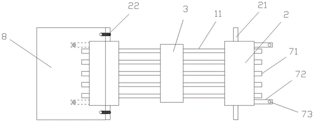
FIG. 2 is a schematic diagram of a top view of an anti-drop and anti-interference terminal wire according to the present invention;
FIG. 3 is a schematic structural view of a wire trimming device for an anti-drop and anti-interference terminal wire according to the present invention;
fig. 4 is a schematic diagram of a plugging surface structure of an anti-drop and anti-interference terminal wire according to the present invention.
In the figure: the wiring board comprises a wiring harness 1, a connecting terminal 2, a wiring device 3, a placing plate 4, a cover plate 5, a buckle structure 6, a plugging surface 7, a terminal socket 8, a signal wire 11, a fixing plate 21, an elastic rubber ring 22, a first half groove 41, a second half groove 51, a shielding layer 52, a plug 71, a positioning column 72 and a positioning hole 73.
[ detailed description ] embodiments
Referring to fig. 1, 2, 3 and 4, the anti-drop and anti-interference terminal wire of the utility model comprises a wire harness 1, wherein two ends of the wire harness 1 are respectively provided with a connecting terminal 2, the wire harness 1 comprises a plurality of signal wires 11, the wire harness 1 is provided with a wire arranging device 3, the wire arranging device 3 comprises a placing plate 4, the upper surface of the placing plate 4 is hinged with a cover plate 5, one side of the cover plate 5 far away from the hinged end is connected with the side wall of the placing plate 4 through a buckling structure 6, the upper surface of the placing plate 4 is provided with a plurality of first half grooves 41, the lower surface of the cover plate 5 is provided with a plurality of second half grooves 51 matched with the first half grooves 41, the first half grooves 41 and the second half grooves 51 are matched to form accommodating cavities which are not communicated with each other, each accommodating cavity is provided with one signal wire 11, the upper surface of the placing plate 4 and the lower surface of the cover plate 5 are provided with a shielding layer 52, the plug-in surface 7 of the connecting terminal 2 is provided with a plurality of plugs 71, the plug-in surface 7 is further provided with two positioning columns 72, the positioning columns 72 are located on two sides of the plugs 71, one side, away from the plug-in surface 7, of each positioning column 72 is provided with a positioning hole 73, the connecting terminal 2 is plugged in a matched terminal socket 8, the terminal socket 8 is provided with a fixing hole matched with the positioning hole 73, a fixing bolt connected with the positioning hole 73 is installed in the fixing hole, fixing plates 21 are arranged on the front side and the rear side of the connecting terminal 2, elastic rubber rings 22 are fixed on the front side and the rear side of the terminal socket 8, the fixing plates 21 are fixed on the terminal socket 8 through the elastic rubber rings 22, and the positioning holes 73 are threaded holes.
The working process of the utility model is as follows:
in the working process of the anti-drop anti-interference terminal wire, the plug-in surface 7 is provided with the positioning column 72, the positioning column 72 is provided with the positioning hole 73, and the positioning column 73 can play a role in guiding and positioning in the plug-in process and can fix the positioning hole to the terminal socket 8 through the fixing bolt; the wire arranging device 3 is arranged to arrange and place the wire harnesses, and the shielding layer 52 is arranged to improve the anti-interference performance between the signal wires 11.
The above embodiments are illustrative of the present invention, and are not intended to limit the present invention, and any simple modifications of the present invention are within the scope of the present invention.

Claims (4)

1. The utility model provides an anticreep anti-interference terminal line which characterized in that: the wire harness comprises a wire harness (1), connecting terminals (2) are arranged at two ends of the wire harness (1), the wire harness (1) comprises a plurality of signal wires (11), a wire arranging device (3) is arranged on the wire harness (1), the wire arranging device (3) comprises a placing plate (4), a cover plate (5) is hinged to the upper surface of the placing plate (4), one side, far away from the hinged end, of the cover plate (5) is connected with the side wall of the placing plate (4) through a buckle structure (6), a plurality of first half grooves (41) are arranged on the upper surface of the placing plate (4), a plurality of second half grooves (51) matched with the first half grooves (41) are arranged on the lower surface of the cover plate (5), the first half grooves (41) and the second half grooves (51) are matched to form accommodating cavities, the accommodating cavities are not communicated with each other, one signal wire (11) is placed in each accommodating cavity, the upper surface of the placing plate (4) and the lower surface of the cover plate (5) are provided with shielding layers (52), a plurality of plugs (71) are arranged on the plug-in surface (7) of the connecting terminal (2), two positioning columns (72) are further arranged on the plug-in surface (7), the positioning columns (72) are located on two sides of the plugs (71), and one side, far away from the plug-in surface (7), of each positioning column (72) is provided with a positioning hole (73).
2. The drop-resistant, interference-resistant terminal wire of claim 1, wherein: the connecting terminal (2) is inserted into a matched terminal socket (8), a fixing hole matched with the positioning hole (73) is formed in the terminal socket (8), and a fixing bolt connected with the positioning hole (73) is installed in the fixing hole.
3. The drop-resistant, interference-resistant terminal wire of claim 2, wherein: both sides are equipped with fixed plate (21) around connecting terminal (2), both sides are fixed with elasticity rubber circle (22) around terminal socket (8), fixed plate (21) are fixed on terminal socket (8) through elasticity rubber circle (22).
4. The drop-resistant, interference-resistant terminal wire of claim 3, wherein: the positioning hole (73) is a threaded hole.
CN202122683141.6U 2021-11-04 2021-11-04 Anti-interference terminal line of anticreep Expired - Fee Related CN216289318U (en)

Priority Applications (1)

Application Number Priority Date Filing Date Title
CN202122683141.6U CN216289318U (en) 2021-11-04 2021-11-04 Anti-interference terminal line of anticreep

Applications Claiming Priority (1)

Application Number Priority Date Filing Date Title
CN202122683141.6U CN216289318U (en) 2021-11-04 2021-11-04 Anti-interference terminal line of anticreep

Publications (1)

Publication Number Publication Date
CN216289318U true CN216289318U (en) 2022-04-12

Family

ID=81005829

Family Applications (1)

Application Number Title Priority Date Filing Date
CN202122683141.6U Expired - Fee Related CN216289318U (en) 2021-11-04 2021-11-04 Anti-interference terminal line of anticreep

Country Status (1)

Country Link
CN (1) CN216289318U (en)

Similar Documents

Publication Publication Date Title
WO2012116505A1 (en) Socket electrical connector
CN204834936U (en) Hair button inter -plate electric connector
CN205565175U (en) Plug connector
WO2012116504A1 (en) Electrical connector
CN201758219U (en) Network connector with angled socket
CN219959577U (en) Wiring structure of electric cabinet
CN219874306U (en) an electrical connector
CN216289196U (en) Conveniently-assembled double-socket terminal wire
CN106921083A (en) A kind of connector construction and its terminal structure for having fastening terminal
CN111883957A (en) Hybrid wire-to-wire connector structure and power supply device with same
CN101931152B (en) electrical connector
CN102201251B (en) Storage device connection structure and composite connector thereof
CN201435478Y (en) an electrical connector
CN204947277U (en) Combined card-inserted connector
CN204464541U (en) An 8PIN compatible data cable male head
CN211456099U (en) Six-type non-shielding module
CN201270302Y (en) Connector
CN202405500U (en) Electric connector
CN201312037Y (en) Electric connector
CN207303600U (en) A kind of patchcord for being used to charge with data transfer
CN2709982Y (en) Cable test table with separate channel
CN221614235U (en) Electronic circuit connector
CN214898935U (en) Cable connecting assembly for semiconductor production equipment
CN222802253U (en) A cable connector with pressure resistance function
CN221353278U (en) Detachable charging head

Legal Events

Date Code Title Description
GR01 Patent grant
GR01 Patent grant
CF01 Termination of patent right due to non-payment of annual fee

Granted publication date: 20220412

CF01 Termination of patent right due to non-payment of annual fee