CN216283418U - Die steel detection device - Google Patents
Die steel detection device Download PDFInfo
- Publication number
- CN216283418U CN216283418U CN202122937417.9U CN202122937417U CN216283418U CN 216283418 U CN216283418 U CN 216283418U CN 202122937417 U CN202122937417 U CN 202122937417U CN 216283418 U CN216283418 U CN 216283418U
- Authority
- CN
- China
- Prior art keywords
- movable mounting
- mounting seat
- conveyor belt
- movable
- die steel
- Prior art date
- Legal status (The legal status is an assumption and is not a legal conclusion. Google has not performed a legal analysis and makes no representation as to the accuracy of the status listed.)
- Expired - Fee Related
Links
- 238000001514 detection method Methods 0.000 title claims abstract description 55
- 229910000831 Steel Inorganic materials 0.000 title claims abstract description 31
- 239000010959 steel Substances 0.000 title claims abstract description 31
- 230000005540 biological transmission Effects 0.000 claims abstract description 30
- 238000003475 lamination Methods 0.000 claims abstract description 19
- 238000010030 laminating Methods 0.000 claims description 14
- 230000001360 synchronised effect Effects 0.000 claims description 7
- 238000012360 testing method Methods 0.000 abstract description 3
- 238000010586 diagram Methods 0.000 description 5
- 238000009434 installation Methods 0.000 description 4
- 238000000034 method Methods 0.000 description 3
- 238000012545 processing Methods 0.000 description 3
- 238000007689 inspection Methods 0.000 description 2
- 230000004075 alteration Effects 0.000 description 1
- 230000009286 beneficial effect Effects 0.000 description 1
- 238000013461 design Methods 0.000 description 1
- 230000009347 mechanical transmission Effects 0.000 description 1
- 238000012986 modification Methods 0.000 description 1
- 230000004048 modification Effects 0.000 description 1
- 238000006467 substitution reaction Methods 0.000 description 1
Images


Landscapes
- Press Drives And Press Lines (AREA)
Abstract
本实用新型公开了用于模具钢检测装置,包括放置底座和检测区域,所述检测区域位于放置底座的中部,且检测区域的左右两侧分别设置有第一输送带和第二输送带,所述检测区域的上下两侧均设置有贴合滚筒,且第一输送带和第二输送带的上平面高度和下方贴合滚筒的最高点高度相等,所述贴合滚筒的中部设置有传动转轴,且贴合滚筒和传动转轴之间均匀分布有连接弹簧。该用于模具钢检测装置,可通过贴合滚筒配合第一输送带和第二输送带进行连续输送检测,同时设置有配合活动安装板调整安装的传动皮带轮驱动结构,便于灵活适应工件规格进行调整的同时,保持连续的输送传动,以便于进行批量连续检测,提高整体的工作效率。

The utility model discloses a detection device for die steel, comprising a placement base and a detection area, the detection area is located in the middle of the placement base, and the left and right sides of the detection area are respectively provided with a first conveyor belt and a second conveyor belt. The upper and lower sides of the detection area are provided with lamination rollers, and the height of the upper plane of the first conveyor belt and the second conveyor belt is equal to the height of the highest point of the lower lamination cylinder, and the middle of the lamination cylinder is provided with a transmission shaft , and connecting springs are evenly distributed between the fitting roller and the transmission shaft. This device is used for die steel detection, which can be continuously conveyed and detected by fitting the roller with the first conveyor belt and the second conveyor belt. At the same time, it is equipped with a drive structure of a drive pulley that can be adjusted and installed with the movable mounting plate, which is convenient for flexible adjustment to the workpiece specifications. At the same time, it maintains continuous transmission and transmission to facilitate continuous batch testing and improve overall work efficiency.
Description
技术领域technical field
本实用新型涉及模具钢相关技术领域,具体为用于模具钢检测装置。The utility model relates to the related technical field of die steel, in particular to a detection device for die steel.
背景技术Background technique
在模具钢的加工过程中,通常对钢材工件的表面平整度等参数具有一定的要求,为了满足模具的精加工需求,需要通过相应的检测来保证规格参数稳定,避免影响后续的产品加工质量。In the process of die steel processing, there are usually certain requirements for the surface flatness and other parameters of the steel workpiece. In order to meet the finishing requirements of the die, it is necessary to ensure the stability of the specifications and parameters through corresponding testing, so as to avoid affecting the subsequent product processing quality.
现有的检测手段如中国专利公开号为CN210603152U的一种小型初加工模具钢材六面平整度检测装置,通过设置有进行灵活贴合检测的活动贴合板,配合活动盘和传动齿轮的同步机械传动,可以便于通过弹性机械结构的颤动直接进行观察检测,但是该装置适应的模具钢规格有限,不便于适应模具钢规格进行一定的调整检测,不便于一些较大的板条状模具钢检测,特别是上下料过程较为不便,在批量连续检测时影响整体的检测效率。Existing detection means, such as a small-scale preliminary processing die steel six-sided flatness detection device with Chinese Patent Publication No. CN210603152U, is provided with a movable lamination plate for flexible lamination detection, and is matched with the synchronous mechanical transmission of the movable disc and the transmission gear. , which can facilitate direct observation and detection through the vibration of the elastic mechanical structure, but the specifications of the die steel that the device adapts to are limited, it is not convenient to adapt to the specifications of the die steel for certain adjustment and detection, and it is not convenient for the detection of some larger strip-shaped die steels, especially The loading and unloading process is relatively inconvenient, which affects the overall detection efficiency during continuous batch testing.
针对上述问题,在原有用于模具钢检测装置的基础上进行创新设计。In view of the above problems, an innovative design is carried out on the basis of the original detection device for die steel.
实用新型内容Utility model content
本实用新型的目的在于提供用于模具钢检测装置,以解决上述背景技术中提出模具钢检测装置使用灵活性交叉,检测效率较低的问题。The purpose of the present utility model is to provide a detection device for die steel, so as to solve the problems of the above-mentioned background art that the detection device for die steel is flexible in use, and the detection efficiency is low.
为实现上述目的,本实用新型提供如下技术方案:用于模具钢检测装置,包括放置底座和检测区域;In order to achieve the above-mentioned purpose, the utility model provides the following technical solutions: used for a die steel detection device, including a placement base and a detection area;
所述检测区域位于放置底座的中部,且检测区域的左右两侧分别设置有第一输送带和第二输送带;The detection area is located in the middle of the placing base, and the left and right sides of the detection area are respectively provided with a first conveyor belt and a second conveyor belt;
所述检测区域的上下两侧均设置有贴合滚筒,且第一输送带和第二输送带的上平面高度和下方贴合滚筒的最高点高度相等;The upper and lower sides of the detection area are provided with lamination rollers, and the height of the upper plane of the first conveyor belt and the second conveyor belt is equal to the height of the highest point of the lower lamination roller;
所述贴合滚筒的中部设置有传动转轴,且贴合滚筒和传动转轴之间均匀分布有连接弹簧。A transmission rotating shaft is arranged in the middle of the laminating drum, and connecting springs are evenly distributed between the laminating drum and the transmission rotating shaft.
优选的,所述放置底座的前后侧边焊接有固定侧板,且固定侧板的上下端分别设置有活动安装座和固定安装座,并且贴合滚筒安装于活动安装座和固定安装座的外侧。Preferably, the front and rear sides of the placing base are welded with fixed side plates, and the upper and lower ends of the fixed side plates are respectively provided with a movable mounting seat and a fixed mounting seat, and the fit roller is installed on the outer side of the movable mounting seat and the fixed mounting seat .
采用上述技术方案,通过上下面的贴合滚筒贴合模具钢进行双面检测,便于板条状模具钢的表面快速检测。By adopting the above technical scheme, the upper and lower laminating rollers are attached to the die steel for double-sided detection, which facilitates the rapid detection of the surface of the strip-shaped die steel.
优选的,所述固定侧板的上半段开设有活动滑槽,且活动滑槽的滑动方向和第一输送带的上表面相互垂直,并且活动安装座和侧边对应的贴合滚筒整体沿活动滑槽构成滑动升降结构;Preferably, the upper half of the fixed side plate is provided with a movable chute, and the sliding direction of the movable chute and the upper surface of the first conveyor belt are perpendicular to each other, and the movable mounting seat and the fitting roller corresponding to the side are integrally The movable chute constitutes a sliding lifting structure;
所述固定安装座和固定侧板为焊接一体化结构。The fixed mounting seat and the fixed side plate are of a welded integrated structure.
采用上述技术方案,通过活动安装座和固定安装座的相对活动设置,便于外侧的贴合滚筒适应不同模具钢的规格。By adopting the above technical solution, through the relative movable arrangement of the movable mounting seat and the fixed mounting seat, it is convenient for the outside lamination roller to adapt to the specifications of different die steels.
优选的,所述活动滑槽的中部贯穿设置有调节螺杆,且调节螺杆的中轴线和活动滑槽的滑动方向相互重合,并且活动安装座通过调节螺杆构成螺纹传动结构;Preferably, an adjustment screw is arranged through the middle of the movable chute, and the central axis of the adjustment screw and the sliding direction of the movable chute coincide with each other, and the movable mounting seat forms a threaded transmission structure through the adjustment screw;
所述活动安装座的顶部设置有转柄,且转柄和固定侧板的顶端之间设置有限位销。A turning handle is arranged on the top of the movable mounting seat, and a limit pin is arranged between the turning handle and the top end of the fixed side plate.
采用上述技术方案,可通过调节螺杆的丝杆传动对活动安装座的升降进行稳定调整,配合限位销的限位调整合适的检测间距。By adopting the above technical solution, the lifting and lowering of the movable mounting seat can be stably adjusted by adjusting the screw drive of the screw, and the appropriate detection distance can be adjusted with the limit of the limit pin.
优选的,所述活动安装座和固定安装座的外侧均安装有活动安装板,且活动安装板以传动转轴所在轴心为转轴构成旋转结构,并且上下活动安装板整体构成横卧的“V”形结构。Preferably, a movable mounting plate is installed on the outer side of the movable mounting seat and the fixed mounting seat, and the movable mounting plate takes the axis where the transmission shaft is located as the rotation axis to form a rotating structure, and the upper and lower movable mounting plates form a horizontal "V" as a whole shape structure.
采用上述技术方案,活动设置的上下活动安装板可便于配合活动安装座和固定安装座的相对升降结构同时保持整体的联动关系。With the above technical solution, the movable upper and lower movable mounting plates can be easily matched with the relative lifting structures of the movable mounting seat and the fixed mounting seat while maintaining the overall linkage relationship.
优选的,所述活动安装板的内侧安装有传动皮带轮,且上下活动安装板的相交处安装有驱动电机,并且上下活动安装板的相交处在驱动电机的轴端外侧构成旋转结构;Preferably, a drive pulley is installed on the inner side of the movable mounting plate, and a drive motor is installed at the intersection of the upper and lower movable installation plates, and the intersection of the upper and lower movable installation plates forms a rotating structure outside the shaft end of the drive motor;
所述驱动电机通过传动皮带轮同时对上下两侧的传动转轴构成同步传动结构。The drive motor forms a synchronous transmission structure for the transmission shafts on the upper and lower sides at the same time through the transmission pulley.
采用上述技术方案,便于通过单电机同步带动上下贴合滚筒的同步传动,保持贴合滚筒的持续转动,配合连接弹簧的弹性支撑,轻质光面的贴合滚筒在贴合工件表面滚动时会因工件表面的不平整而产生明显抖动。By adopting the above technical solution, it is convenient to use a single motor to synchronously drive the synchronous transmission of the upper and lower laminating rollers, maintain the continuous rotation of the laminating roller, and cooperate with the elastic support of the connecting spring. Visible jitter occurs due to the uneven surface of the workpiece.
与现有技术相比,本实用新型的有益效果是:该用于模具钢检测装置,Compared with the prior art, the beneficial effects of the present utility model are: the detection device for die steel,
1、可通过贴合滚筒配合第一输送带和第二输送带进行连续输送检测,在装置的检测使用过程中,上下方的贴合滚筒同时贴合工件表面进行滚动,配合连接弹簧的弹性支撑,可在工件表面不平整时通过贴合滚筒的偏心发生抖动,从而便于观测,无需额外传感器等设备成本较低,且便于批量工件的连续检测,有效提高整体的检测效率;1. The first conveyor belt and the second conveyor belt can be used for continuous conveying detection through the lamination roller. During the detection and use of the device, the upper and lower lamination rollers roll against the surface of the workpiece at the same time, and cooperate with the elastic support of the connecting spring. , it can shake the eccentricity of the lamination roller when the surface of the workpiece is uneven, so as to facilitate observation, without the need for additional sensors and other equipment, the cost is low, and it is convenient for continuous detection of batches of workpieces, effectively improving the overall detection efficiency;
2、设置有配合活动安装板调整安装的传动皮带轮驱动结构,在装置的检测使用过程中,上下两侧的贴合滚筒配合活动安装座和活动滑槽的滑动升降结构可以便于适应检测工件的规格进行相应的灵活调整,同时贴合滚筒的传动皮带轮传动结构通过活动安装板的可偏转活动安装,可以便于在活动安装座灵活升降的同时保持上下贴合滚筒的同步传动,无需上下额外设置独立的电机设备,降低使用成本。2. There is a drive structure of the drive pulley that can be adjusted and installed with the movable mounting plate. During the detection and use of the device, the upper and lower sides of the fitting rollers cooperate with the sliding and lifting structure of the movable mounting seat and the movable chute, which can easily adapt to the specifications of the workpiece to be detected. Make corresponding flexible adjustments, and at the same time, the drive pulley drive structure of the laminating roller is installed through the deflectable movable mounting plate, which can facilitate the synchronous transmission of the upper and lower laminating rollers while the movable mounting seat is flexibly raised and lowered, without the need for additional upper and lower independent installations. Motor equipment, reduce the cost of use.
附图说明Description of drawings
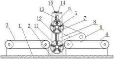
图1为本实用新型正面剖视结构示意图;Fig. 1 is the front sectional structure schematic diagram of the utility model;
图2为本实用新型图1中a处放大结构示意图;Fig. 2 is the enlarged structural schematic diagram at a place in Fig. 1 of the utility model;
图3为本实用新型活动安装座侧面剖视结构示意图;Fig. 3 is the side sectional structural schematic diagram of the movable mounting seat of the utility model;
图4为本实用新型活动安装板正面剖视结构示意图;Fig. 4 is the front cross-sectional structural schematic diagram of the movable mounting plate of the utility model;
图5为本实用新型正面结构示意图。Figure 5 is a schematic diagram of the front structure of the utility model.
图中:1、放置底座;2、检测区域;3、第一输送带;4、第二输送带;5、贴合滚筒;6、传动转轴;7、连接弹簧;8、固定侧板;9、活动安装板;10、活动安装座;11、固定安装座;12、活动滑槽;13、调节螺杆;14、转柄;15、限位销;16、传动皮带轮;17、驱动电机。In the figure: 1. Place the base; 2. Detection area; 3. The first conveyor belt; 4. The second conveyor belt; , movable mounting plate; 10, movable mounting seat; 11, fixed mounting seat; 12, movable chute; 13, adjusting screw; 14, turning handle; 15, limit pin; 16, transmission pulley; 17, drive motor.
具体实施方式Detailed ways
下面将结合本实用新型实施例中的附图,对本实用新型实施例中的技术方案进行清楚、完整地描述,显然,所描述的实施例仅仅是本实用新型一部分实施例,而不是全部的实施例。基于本实用新型中的实施例,本领域普通技术人员在没有做出创造性劳动前提下所获得的所有其他实施例,都属于本实用新型保护的范围。The technical solutions in the embodiments of the present utility model will be clearly and completely described below with reference to the accompanying drawings in the embodiments of the present utility model. Obviously, the described embodiments are only a part of the embodiments of the present utility model, rather than all the implementations. example. Based on the embodiments of the present invention, all other embodiments obtained by those of ordinary skill in the art without creative work fall within the protection scope of the present invention.
请参阅图1-5,本实用新型提供技术方案:用于模具钢检测装置,包括放置底座1和检测区域2,检测区域2位于放置底座1的中部,且检测区域2的左右两侧分别设置有第一输送带3和第二输送带4,检测区域2的上下两侧均设置有贴合滚筒5,且第一输送带3和第二输送带4的上平面高度和下方贴合滚筒5的最高点高度相等,贴合滚筒5的中部设置有传动转轴6,且贴合滚筒5和传动转轴6之间均匀分布有连接弹簧7,放置底座1的前后侧边焊接有固定侧板8,且固定侧板8的上下端分别设置有活动安装座10和固定安装座11,并且贴合滚筒5安装于活动安装座10和固定安装座11的外侧,通过上下面的贴合滚筒5贴合模具钢进行双面检测,便于板条状模具钢的表面快速检测。Please refer to FIGS. 1-5, the present utility model provides a technical solution: a detection device for die steel, including a
结合图1-3所示,固定侧板8的上半段开设有活动滑槽12,且活动滑槽12的滑动方向和第一输送带3的上表面相互垂直,并且活动安装座10和侧边对应的贴合滚筒5整体沿活动滑槽12构成滑动升降结构,固定安装座11和固定侧板8为焊接一体化结构,通过活动安装座10和固定安装座11的相对活动设置,便于外侧的贴合滚筒5适应不同模具钢的规格,活动滑槽12的中部贯穿设置有调节螺杆13,且调节螺杆13的中轴线和活动滑槽12的滑动方向相互重合,并且活动安装座10通过调节螺杆13构成螺纹传动结构,活动安装座10的顶部设置有转柄14,且转柄14和固定侧板8的顶端之间设置有限位销15,可通过调节螺杆13的丝杆传动对活动安装座10的升降进行稳定调整,配合限位销15的限位调整合适的检测间距。1-3, the upper half of the
结合图3-5所示,活动安装座10和固定安装座11的外侧均安装有活动安装板9,且活动安装板9以传动转轴6所在轴心为转轴构成旋转结构,并且上下活动安装板9整体构成横卧的“V”形结构,活动设置的上下活动安装板9可便于配合活动安装座10和固定安装座11的相对升降结构同时保持整体的联动关系,活动安装板9的内侧安装有传动皮带轮16,且上下活动安装板9的相交处安装有驱动电机17,并且上下活动安装板9的相交处在驱动电机17的轴端外侧构成旋转结构,驱动电机17通过传动皮带轮16同时对上下两侧的传动转轴6构成同步传动结构,便于通过单电机同步带动上下贴合滚筒5的同步传动,保持贴合滚筒5的持续转动,配合连接弹簧7的弹性支撑,轻质光面的贴合滚筒5在贴合工件表面滚动时会因工件表面的不平整而产生明显抖动。3-5, the
工作原理:在使用该用于模具钢检测装置时,可直接将模具钢检测工件通过第一输送带3和第二输送带4保持持续输送进行连续检测,在检测前,可通过调节螺杆13的旋转带动活动安装座10沿活动滑槽12升降调整上下贴合滚筒5至合适的检测间距,工件通过检测区域2时,上下贴合滚筒5贴合工件的上下表面,同时在驱动电机17和传动皮带轮16的驱动下带动贴合滚筒5和传动转轴6快速转动,当工件表面不平整时,贴合滚筒5会因偏心变化发生明显抖动,方便进行直接观测。Working principle: When using the die steel detection device, the die steel detection workpiece can be directly continuously conveyed through the
本说明书中未作详细描述的内容属于本领域专业技术人员公知的现有技术,尽管已经示出和描述了本实用新型的实施例,对于本领域的普通技术人员而言,可以理解在不脱离本实用新型的原理和精神的情况下可以对这些实施例进行多种变化、修改、替换和变型,本实用新型的范围由所附权利要求及其等同物限定。The content not described in detail in this specification belongs to the prior art known to those skilled in the art. Although the embodiments of the present invention have been shown and described, those of ordinary skill in the art can understand that the Various changes, modifications, substitutions and alterations may be made to these embodiments within the principles and spirit of the present invention, and the scope of the present invention is defined by the appended claims and their equivalents.
Claims (6)
Priority Applications (1)
| Application Number | Priority Date | Filing Date | Title |
|---|---|---|---|
| CN202122937417.9U CN216283418U (en) | 2021-11-27 | 2021-11-27 | Die steel detection device |
Applications Claiming Priority (1)
| Application Number | Priority Date | Filing Date | Title |
|---|---|---|---|
| CN202122937417.9U CN216283418U (en) | 2021-11-27 | 2021-11-27 | Die steel detection device |
Publications (1)
| Publication Number | Publication Date |
|---|---|
| CN216283418U true CN216283418U (en) | 2022-04-12 |
Family
ID=81038785
Family Applications (1)
| Application Number | Title | Priority Date | Filing Date |
|---|---|---|---|
| CN202122937417.9U Expired - Fee Related CN216283418U (en) | 2021-11-27 | 2021-11-27 | Die steel detection device |
Country Status (1)
| Country | Link |
|---|---|
| CN (1) | CN216283418U (en) |
-
2021
- 2021-11-27 CN CN202122937417.9U patent/CN216283418U/en not_active Expired - Fee Related
Similar Documents
| Publication | Publication Date | Title |
|---|---|---|
| CN204450743U (en) | A kind of thicknesser sanding apparatus of bamboo wood board | |
| CN115351669A (en) | Abrasive belt grinding machine for aluminum alloy profile machining | |
| CN101229626B (en) | Sander Conveyor Roller Stand Structure | |
| CN215847316U (en) | Automatic grinding device for plates | |
| CN216542545U (en) | Double-side cleaning and polishing device of copper strip flattening machine | |
| CN211890271U (en) | Sanding machine | |
| CN210816802U (en) | Automatic uncoiler for hardware machining | |
| CN220129165U (en) | Fixed thickness conveyor | |
| CN210358948U (en) | Rotary Feeder for Plate Bending Machines | |
| CN220077676U (en) | Steel conveying limiting structure | |
| CN213671182U (en) | Leveling machine with adjustable lower roll is single | |
| CN206405868U (en) | A kind of misclassification formula double sided sander | |
| CN212218160U (en) | Sheet metal grinds machine roll extrusion structure | |
| CN211915283U (en) | Conveyor is used in sheet metal component production | |
| CN108161616A (en) | A kind of novel timber polishing machine | |
| CN222699408U (en) | Photovoltaic glass edge cleaning roller way | |
| CN209392250U (en) | A structure-optimized folding equipment | |
| CN115351672A (en) | An automatic adjustment device for abrasive belt grinding | |
| CN206855195U (en) | A kind of polished machine | |
| CN217189750U (en) | A wire drawing machine guide roller | |
| CN121821172B (en) | Metal sheet grinds flat burnishing device | |
| CN208450251U (en) | A rapid discharge device for a precision sheet material straightening machine | |
| CN221329999U (en) | Rolling device for processing flour products | |
| CN209937063U (en) | Conveyer belt layering machine | |
| CN218766666U (en) | Hardware CCD full-detection machine with multi-channel output |
Legal Events
| Date | Code | Title | Description |
|---|---|---|---|
| GR01 | Patent grant | ||
| GR01 | Patent grant | ||
| CF01 | Termination of patent right due to non-payment of annual fee | ||
| CF01 | Termination of patent right due to non-payment of annual fee |
Granted publication date: 20220412 |