CN216264337U - Welding tool convenient for adjusting part posture - Google Patents
Welding tool convenient for adjusting part posture Download PDFInfo
- Publication number
- CN216264337U CN216264337U CN202121886549.7U CN202121886549U CN216264337U CN 216264337 U CN216264337 U CN 216264337U CN 202121886549 U CN202121886549 U CN 202121886549U CN 216264337 U CN216264337 U CN 216264337U
- Authority
- CN
- China
- Prior art keywords
- fixed
- block
- welding tool
- threaded rod
- rotating
- Prior art date
- Legal status (The legal status is an assumption and is not a legal conclusion. Google has not performed a legal analysis and makes no representation as to the accuracy of the status listed.)
- Active
Links
- 238000003466 welding Methods 0.000 title claims abstract description 32
- 230000000149 penetrating effect Effects 0.000 claims description 5
- 230000000694 effects Effects 0.000 description 2
- 230000004075 alteration Effects 0.000 description 1
- 230000009286 beneficial effect Effects 0.000 description 1
- 230000007547 defect Effects 0.000 description 1
- 238000006467 substitution reaction Methods 0.000 description 1
Images


Landscapes
- Butt Welding And Welding Of Specific Article (AREA)
Abstract
The utility model discloses a welding tool convenient for adjusting the posture of a part, which comprises a workbench and supporting legs, wherein two sides of the workbench are rotatably connected with the inner side walls of the supporting legs, a first fixing mechanism for fixing a first right-angle plate is arranged on the workbench, a fixing block is fixed on the upper end surface of the workbench, a second fixing mechanism for clamping a second right-angle plate is arranged on the fixing block, and a driving mechanism for rotating the workbench in an inclined manner is arranged on the supporting legs; according to the welding tool, the L-shaped fixing plate, the fixing block and the lifting block are matched, so that the gasket at the tail end of the first threaded rod is abutted against the clamped first right-angle plate, the lower end face of the pressing piece is abutted against the second right-angle plate, and the side wall of the second right-angle plate is abutted against the side wall of the first right-angle plate through the lifting block, so that the welding tool can be suitable for welding of the right-angle plates with different specifications.
Description
Technical Field
The utility model relates to the technical field of welding tools, in particular to a welding tool convenient for adjusting the posture of a component.
Background
For products with special shapes, a welding tool is usually needed during welding, the welding tool is designed according to the welding requirements of parts, and the products are positioned and clamped through the welding tool, so that welding is convenient to realize.
When two right-angle plates are welded together to form a Z shape, the two plates are clamped, fixed and spliced to form a connecting surface, the welding tool is inconvenient to operate, the welding tool cannot adapt to the right-angle plates with different sizes, the support frame and the workbench of the existing welding tool are fixedly connected, and the workbench cannot rotate to adjust the angle.
Disclosure of Invention
The utility model solves the problems that:
(1) when current welding frock was carried out the centre gripping to two right angle boards and is fixed and the concatenation connecting surface, inconvenient operation, and can not adapt to the right angle panel of specification variation in size.
(2) The support frame and the workstation of current welding frock are fixed connection, and the unable rotation angle adjustment of workstation, inconvenient operating personnel welds the straight angle board.
The utility model aims to solve the defects in the prior art, and provides a welding tool convenient for adjusting the posture of a component.
In order to achieve the purpose, the utility model adopts the following technical scheme:
the utility model provides a welding frock convenient to adjustment part gesture, workstation and supporting leg, the both sides of workstation are rotated with the inside wall of supporting leg and are connected, are equipped with the first fixed establishment who is used for fixed first right-angle board on the workstation, and the up end of workstation is fixed with the fixed block, is equipped with the second fixed establishment who is used for centre gripping second right-angle board on the fixed block, is equipped with the actuating mechanism who is used for the slope swivel work head on the supporting leg.
As a further technical scheme, the first fixing mechanism comprises a rectangular groove formed in the upper end face of the workbench, a sliding block is connected in the rectangular groove in a sliding mode, an L-shaped fixing plate is fixed on the upper end face of the sliding block, and a driving assembly used for moving the sliding block is arranged in the rectangular groove.
As a further technical scheme, the driving assembly comprises a first rotating rod which is rotatably connected to the side wall of the rectangular groove, one end of the first rotating rod penetrates through the rectangular groove, a first rotating hand wheel is fixedly sleeved at one end, far away from the rectangular groove, of the first rotating rod, external threads are formed in the outer side wall of the first rotating rod, an internal thread through hole is formed in one side of the sliding block, and the first rotating rod is connected with the sliding block in a meshed mode.
As a further technical scheme, a first supporting seat is fixed on the upper surface of the L-shaped fixing plate, a first threaded rod meshed with the first supporting seat penetrates through the first supporting seat, the first threaded rod penetrates through the L-shaped fixing plate, a gasket is fixed at one end, close to the L-shaped fixing plate, of the first threaded rod, and a second rotating hand wheel is fixedly sleeved at one end, far away from the L-shaped fixing plate, of the first threaded rod.
As a further technical scheme of the present invention, the second fixing mechanism includes a lifting block disposed above the fixing block, a second supporting seat is fixed to one side of the lifting block, a second threaded rod engaged with the second supporting seat is disposed on the second supporting seat in a penetrating manner, a third rotating hand wheel is fixedly sleeved at a tail end of the second threaded rod, and a pressing member is rotatably disposed on a side wall of the second threaded rod.
As a further technical solution of the present invention, a stopper for preventing the pressing member from rotating is fixed to an upper end surface of the second support seat.
As a further technical scheme of the utility model, the upper end surface of the fixed block is provided with a groove, the bottom of the groove is provided with a worm in a penetrating manner, the worm is meshed with the groove, the upper end surface of the worm is fixedly connected with the lifting block, the side wall of the fixed block is provided with a second rotating rod in a penetrating manner, the second rotating rod is rotatably connected with the side wall of the fixed block, the side wall of the second rotating rod is fixedly sleeved with a worm wheel, and the tail end of the second rotating rod is fixedly sleeved with a fourth rotating hand wheel.
As a further technical scheme of the utility model, the driving mechanism comprises a supporting plate fixedly connected to one side of the supporting leg, a first fixing lug is fixed on the upper end surface of the supporting plate, a second fixing lug is fixed on one side of the workbench close to the supporting plate through a connecting block, and a hydraulic rod is rotatably arranged between the first fixing lug and the second fixing lug.
The utility model has the beneficial effects that:
1. through the cooperation of the L type fixed plate that sets up, fixed block and elevator, make the terminal gasket of first threaded rod and the first right angle panel looks butt of centre gripping, the lower terminal surface and the second right angle board looks butt of pressing piece to make the lateral wall of second right angle board and the lateral wall looks butt of first right angle board through the elevator, make this welding frock can be applicable to the right angle board welding of different specifications size.
2. Through the cooperation of the hydraulic stem that sets up, the ear is fixed to first fixed ear and second, when making the flexible end extension of hydraulic stem, make the workstation take place the rotation, make it rotate suitable inclination, make things convenient for operating personnel to press from both sides two right angle boards of tight fixed on the workstation and weld.
Drawings
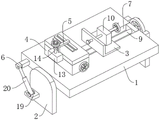
FIG. 1 is a schematic view of the left side of the present invention;
FIG. 2 is a right side schematic view of the present invention;
fig. 3 is a schematic view of the internal structure of the fixing block of the present invention.
In the figure: 1. a work table; 2. supporting legs; 3. a first fixing mechanism; 4. a fixed block; 5. a second fixing mechanism; 6. a drive mechanism; 7. a rectangular groove; 8. an L-shaped fixing plate; 9. a first rotating lever; 10. a first support base; 11. a first threaded rod; 12. a lifting block; 13. a second support seat; 14. a second threaded rod; 15. a pressing member; 16. a worm; 17. a second rotating lever; 18. a worm gear; 19. a support plate; 20. a hydraulic rod.
Detailed Description
To further illustrate the technical means and effects of the present invention adopted to achieve the predetermined objects, the following detailed description of the embodiments, structures, features and effects according to the present invention will be made with reference to the accompanying drawings and preferred embodiments.
Referring to fig. 1-3, a welding frock convenient to adjustment part gesture, includes workstation 1 and supporting leg 2, and the both sides of workstation 1 are rotated with the inside wall of supporting leg 2 and are connected, make workstation 1 can rotate suitable angle, make things convenient for operating personnel to weld the part of centre gripping.
Be equipped with the first fixed establishment 3 that is used for fixed first straight-angle board on workstation 1, first fixed establishment 3 is including seting up the rectangular channel 7 at 1 up end of workstation, sliding connection has the sliding block in the rectangular channel 7, the up end of sliding block is fixed with L type fixed plate 8, be equipped with the drive assembly who is used for removing the sliding block in the rectangular channel 7, the sliding block removes in rectangular channel 7, thereby drive L type fixed plate 8 and remove at workstation 1, the right angle panel of the different specifications is fixed in 11 centre gripping of cooperation first threaded rod.
The drive assembly connects first rotation pole 9 on 7 lateral walls of rectangular channel including rotating, rectangular channel 7 is run through to the one end of first rotation pole 9, the fixed cover of one end that rectangular channel 7 was kept away from to first rotation pole 9 is equipped with first rotation hand wheel, the external screw thread has been seted up on the lateral wall of first rotation pole 9, the internal thread through-hole has been seted up to one side of sliding block, first rotation pole 9 is connected with the sliding block meshing, it then can drive first rotation pole 9 and rotate to rotate first rotation hand wheel, because first rotation pole 9 is with sliding block thread engagement, so when first rotation hand wheel rotates, can drive the sliding block and remove in rectangular channel 7.
The upper surface of L type fixed plate 8 is fixed with first supporting seat 10, run through on the first supporting seat 10 and be provided with the first threaded rod 11 of being connected with it meshing, first threaded rod 11 runs through L type fixed plate 8, first threaded rod 11 is provided with the bearing with the junction of L type fixed plate 8, the one end that first threaded rod 11 is close to L type fixed plate 8 is fixed with the gasket, the fixed cover of one end that L type fixed plate 8 was kept away from to first threaded rod 11 is equipped with the second and rotates the hand wheel, because first threaded rod 11 is connected with meshing on the first supporting seat 10, so when rotating the second and rotating the hand wheel, first threaded rod 11 then can move on first supporting seat 10, until the terminal gasket of first threaded rod 11 and the right angle panel looks butt contact of centre gripping, press from both sides tight fixed to the straight angle panel.
The up end of workstation 1 is fixed with fixed block 4, be equipped with the second fixed establishment 5 that is used for centre gripping second right-angle board on the fixed block 4, second fixed establishment 5 is including setting up the elevator 12 in fixed block 4 top, one side of elevator 12 is fixed with second supporting seat 13, run through on the second supporting seat 13 and be provided with the second threaded rod 14 of being connected with it meshing, the fixed cover of end of second threaded rod 14 is equipped with the third and rotates the hand wheel, it is provided with according to pressing piece 15 to rotate on the lateral wall of second threaded rod, the up end of second supporting seat 13 is fixed with and prevents according to pressing piece 15 pivoted stopper, it rotates the third and rotates the hand wheel, can make second threaded rod 14 reciprocate on second supporting seat 13, the second threaded rod 14 that reciprocates drives and reciprocates together according to pressing piece 15, make it can the right angle panel of different thickness of centre gripping.
The up end of fixed block 4 is seted up flutedly, the bottom of recess runs through and is provided with the worm 16 of being connected with it meshing, the up end and the elevator 12 fixed connection of worm 16, run through on the lateral wall of fixed block 4 and be provided with the second dwang 17 of being connected with it rotation, fixed cover is equipped with worm wheel 18 on the lateral wall of second dwang 17, the terminal fixed cover of second dwang 17 is equipped with the fourth and rotates the hand wheel, when the fourth rotates the hand wheel and rotates, drive second dwang 17 and worm wheel 18 and rotate together, because worm wheel 18 and worm 16 are the meshing connection, so pivoted worm wheel 18 can make worm 16 take elevator 12 to reciprocate, make fixed block 4 can press from both sides the second right angle panel of fixed different specification sizes.
Be equipped with actuating mechanism 6 that is used for slope swivel work head 1 on supporting leg 2, actuating mechanism 6 includes backup pad 19 of fixed connection in supporting leg 2 one side, backup pad 19's up end is fixed with first fixed ear, one side that workstation 1 is close to backup pad 19 is fixed with the fixed ear of second through the connecting block, it is provided with hydraulic stem 20 to rotate between the fixed ear of first fixed ear and second, because workstation 1 rotates with supporting leg 2 and is connected, when the flexible end extension of hydraulic stem 20, can make workstation 1 rotatory to suitable inclination, make things convenient for operating personnel to press from both sides two right-angle plates of tight fixed on the workstation 1 and weld.
When the hydraulic lifting device is used, a first right-angle plate is placed between a fixed block 4 and an L-shaped fixed plate 8, then a first rotating hand wheel is rotated, a sliding block drives the L-shaped fixed plate 8 to move on a workbench 1 until the side wall of the L-shaped fixed plate 8 is abutted against the side wall of the first right-angle plate, then a second rotating hand wheel is rotated, a first threaded rod 11 can move on a first supporting seat 10 until a gasket at the tail end of the first threaded rod 11 is abutted against a clamped first right-angle plate to clamp and fix the first right-angle plate, then the second right-angle plate is placed on the right-angle edge of the fixed block 4, then a third rotating hand wheel is rotated until the lower end face of a pressing piece 15 is abutted against the second right-angle plate, then a fourth rotating hand wheel is rotated to lower adjust the height of a lifting block 12, so that the side wall of the second right-angle plate is abutted against the side wall of the first right-angle plate, and then the telescopic end of a hydraulic rod 20 is extended, make workstation 1 rotatory to suitable inclination, make things convenient for operating personnel to press from both sides two right-angle boards of tight fixed and weld on the workstation 1.
Although the present invention has been described with reference to the preferred embodiments, it should be understood that various changes, substitutions and alterations can be made herein without departing from the spirit and scope of the utility model as defined by the appended claims.
Claims (8)
1. The utility model provides a welding frock convenient to adjustment part gesture, includes workstation (1) and supporting leg (2), its characterized in that, the both sides of workstation (1) are rotated with the inside wall of supporting leg (2) and are connected, are equipped with first fixed establishment (3) that are used for fixed first right angle board on workstation (1), and the up end of workstation (1) is fixed with fixed block (4), is equipped with second fixed establishment (5) that are used for centre gripping second right angle board on fixed block (4), is equipped with actuating mechanism (6) that are used for slope swivel work head (1) on supporting leg (2).
2. The welding tool convenient for adjusting the posture of a component according to claim 1, wherein the first fixing mechanism (3) comprises a rectangular groove (7) formed in the upper end face of the workbench (1), a sliding block is connected in the rectangular groove (7) in a sliding mode, an L-shaped fixing plate (8) is fixed on the upper end face of the sliding block, and a driving assembly used for moving the sliding block is arranged in the rectangular groove (7).
3. The welding tool convenient for adjusting the posture of a component as claimed in claim 2, wherein the driving assembly comprises a first rotating rod (9) rotatably connected to a side wall of the rectangular groove (7), one end of the first rotating rod (9) penetrates through the rectangular groove (7), a first rotating hand wheel is fixedly sleeved at one end of the first rotating rod (9) far away from the rectangular groove (7), an external thread is formed on an outer side wall of the first rotating rod (9), an internal thread through hole is formed in one side of the sliding block, and the first rotating rod (9) is connected with the sliding block in a meshed manner.
4. The welding tool convenient for adjusting the posture of a component as claimed in claim 2, wherein a first supporting seat (10) is fixed on the upper surface of the L-shaped fixing plate (8), a first threaded rod (11) meshed with the first supporting seat (10) penetrates through the first supporting seat (10), the first threaded rod (11) penetrates through the L-shaped fixing plate (8), a gasket is fixed at one end of the first threaded rod (11) close to the L-shaped fixing plate (8), and a second rotating hand wheel is fixedly sleeved at one end of the first threaded rod (11) far away from the L-shaped fixing plate (8).
5. The welding tool convenient for adjusting the posture of a component according to claim 1, wherein the second fixing mechanism (5) comprises a lifting block (12) arranged above the fixing block (4), a second supporting seat (13) is fixed on one side of the lifting block (12), a second threaded rod (14) meshed with the second supporting seat (13) penetrates through the second supporting seat (13), a third rotating hand wheel is fixedly sleeved at the tail end of the second threaded rod (14), and a pressing piece (15) is rotatably arranged on the side wall of the second threaded rod (14).
6. The welding tool convenient for adjusting the posture of a component according to claim 5, wherein a limiting block for preventing the pressing piece (15) from rotating is fixed on the upper end face of the second supporting seat (13).
7. The welding tool convenient for adjusting the posture of a component according to claim 5, wherein a groove is formed in the upper end surface of the fixed block (4), a worm (16) meshed with the groove is arranged at the bottom of the groove in a penetrating manner, the upper end surface of the worm (16) is fixedly connected with the lifting block (12), a second rotating rod (17) rotatably connected with the fixed block (4) is arranged on the side wall of the fixed block (4) in a penetrating manner, a worm wheel (18) is fixedly sleeved on the side wall of the second rotating rod (17), and a fourth rotating hand wheel is fixedly sleeved at the tail end of the second rotating rod (17).
8. The welding tool convenient to adjust the posture of a component according to claim 1, wherein the driving mechanism (6) comprises a supporting plate (19) fixedly connected to one side of the supporting leg (2), a first fixing lug is fixed on the upper end face of the supporting plate (19), a second fixing lug is fixed on one side, close to the supporting plate (19), of the workbench (1) through a connecting block, and a hydraulic rod (20) is rotatably arranged between the first fixing lug and the second fixing lug.
Priority Applications (1)
| Application Number | Priority Date | Filing Date | Title |
|---|---|---|---|
| CN202121886549.7U CN216264337U (en) | 2021-08-12 | 2021-08-12 | Welding tool convenient for adjusting part posture |
Applications Claiming Priority (1)
| Application Number | Priority Date | Filing Date | Title |
|---|---|---|---|
| CN202121886549.7U CN216264337U (en) | 2021-08-12 | 2021-08-12 | Welding tool convenient for adjusting part posture |
Publications (1)
| Publication Number | Publication Date |
|---|---|
| CN216264337U true CN216264337U (en) | 2022-04-12 |
Family
ID=81060160
Family Applications (1)
| Application Number | Title | Priority Date | Filing Date |
|---|---|---|---|
| CN202121886549.7U Active CN216264337U (en) | 2021-08-12 | 2021-08-12 | Welding tool convenient for adjusting part posture |
Country Status (1)
| Country | Link |
|---|---|
| CN (1) | CN216264337U (en) |
-
2021
- 2021-08-12 CN CN202121886549.7U patent/CN216264337U/en active Active
Similar Documents
| Publication | Publication Date | Title |
|---|---|---|
| CN203993272U (en) | A kind of clamping device | |
| CN210147036U (en) | Clamp for mechanical drilling | |
| CN106975947A (en) | A kind of grip device of reasonable in design | |
| CN218745707U (en) | Liftable rotatory welding jig platform | |
| CN201900350U (en) | a welding machine | |
| CN202591809U (en) | Argon arc welding system of motor stator robot | |
| CN213470146U (en) | Automobile parts welds dress anchor clamps | |
| CN203401251U (en) | Adjustable welding jig | |
| CN216829352U (en) | Aluminium alloy welding machine is used in door and window production | |
| CN217142924U (en) | A flip-up welding table | |
| CN212471158U (en) | Fixing clamp for processing storage battery box | |
| CN215200352U (en) | Clamping device of full-automatic welding machine | |
| CN211102340U (en) | Automatic double-sided welding equipment based on P L C control | |
| CN211387843U (en) | Clamp structure for CNC (computer numerical control) machining | |
| CN219542400U (en) | Workpiece machining clamping device | |
| CN217965574U (en) | Welding tool for machining limiter | |
| CN214685016U (en) | Friction stir welding double-sided welding clamping device | |
| CN207104065U (en) | A kind of automatic soldering device | |
| CN214978373U (en) | DC soldering machine handle swing buffer structure | |
| CN116000408A (en) | An oil cylinder square circular seam welding equipment | |
| CN215393292U (en) | A kind of automatic welding equipment for butt welding flange with neck | |
| CN224059068U (en) | Frock clamp that automobile punching part projection welding used | |
| CN222492789U (en) | Automatic change welding equipment positioning mechanism | |
| CN222806384U (en) | A fixing device for gantry welding | |
| CN222932046U (en) | Work or material rest supporting leg welding positioning tool |
Legal Events
| Date | Code | Title | Description |
|---|---|---|---|
| GR01 | Patent grant | ||
| GR01 | Patent grant |