CN216251594U - Laser water cooling machine - Google Patents
Laser water cooling machine Download PDFInfo
- Publication number
- CN216251594U CN216251594U CN202123114435.3U CN202123114435U CN216251594U CN 216251594 U CN216251594 U CN 216251594U CN 202123114435 U CN202123114435 U CN 202123114435U CN 216251594 U CN216251594 U CN 216251594U
- Authority
- CN
- China
- Prior art keywords
- water
- laser
- cooling machine
- shell
- control panel
- Prior art date
- Legal status (The legal status is an assumption and is not a legal conclusion. Google has not performed a legal analysis and makes no representation as to the accuracy of the status listed.)
- Expired - Fee Related
Links
- XLYOFNOQVPJJNP-UHFFFAOYSA-N water Substances O XLYOFNOQVPJJNP-UHFFFAOYSA-N 0.000 title claims abstract description 90
- 238000001816 cooling Methods 0.000 title claims abstract description 33
- 230000001012 protector Effects 0.000 claims abstract description 7
- 239000003507 refrigerant Substances 0.000 claims description 6
- 238000009423 ventilation Methods 0.000 claims description 5
- 239000007788 liquid Substances 0.000 claims description 4
- 238000001035 drying Methods 0.000 claims description 3
- 230000001681 protective effect Effects 0.000 claims description 3
- 230000005855 radiation Effects 0.000 claims 1
- 230000000694 effects Effects 0.000 abstract description 3
- 230000007613 environmental effect Effects 0.000 abstract description 2
- 238000005057 refrigeration Methods 0.000 description 6
- 238000010586 diagram Methods 0.000 description 4
- 239000000498 cooling water Substances 0.000 description 3
- 238000005265 energy consumption Methods 0.000 description 2
- 238000009825 accumulation Methods 0.000 description 1
- 238000005516 engineering process Methods 0.000 description 1
- 238000001704 evaporation Methods 0.000 description 1
- 230000008020 evaporation Effects 0.000 description 1
- 230000010354 integration Effects 0.000 description 1
- 238000004519 manufacturing process Methods 0.000 description 1
- 238000000034 method Methods 0.000 description 1
Images


Landscapes
- Devices That Are Associated With Refrigeration Equipment (AREA)
Abstract
本实用新型提供了一种激光水冷机,壳体前部安装有控制面板,控制面板中安装有开关和指示灯,控制面板上还连接有温控器;壳体后部安装有进水接头、出水接头、断水保护接头和电源线接头,出水接头位于壳体内侧的部分连接有水流保护器,壳体后部开设有散热风扇开口和排水口,散热风扇开口内侧安装有散热风扇,散热风扇内侧安装有冷凝器;壳体内部上侧安装有水箱,壳体上部开设有通孔,通孔内穿过有水箱进水口,水箱和排水口之间通过水管连接,壳体内部下侧安装有压缩机,压缩机和冷凝器之间安装有蒸发器。激光水冷机结构紧凑、体积小,运输成本低,制冷效果好,节能环保,可以放在机器里面工作,安装方便,占用空间小。
The utility model provides a laser water cooler. A control panel is installed at the front of the casing, switches and indicator lights are installed in the control panel, and a temperature controller is also connected to the control panel; The water outlet connector, the water-break protection connector and the power cord connector, the water outlet connector is connected to the water flow protector on the inner side of the casing, the cooling fan opening and the drain port are opened at the rear of the housing, the cooling fan is installed inside the cooling fan opening, and the inner side of the cooling fan is provided with a cooling fan. A condenser is installed; a water tank is installed on the upper side of the casing, a through hole is opened on the upper part of the casing, and a water inlet of the water tank passes through the through hole. , an evaporator is installed between the compressor and the condenser. The laser water cooler has compact structure, small volume, low transportation cost, good cooling effect, energy saving and environmental protection.
Description
技术领域technical field
本实用新型属于激光器辅助设备技术领域,具体属于一种激光水冷机。The utility model belongs to the technical field of laser auxiliary equipment, in particular to a laser water cooler.
背景技术Background technique
工作中的激光机会产生比较大的热量,热量的堆积会影响生产效率和激光头的精度,甚至会对激光机造成损坏,所以必须通过其他手段将激光机产生的热量带走,一般是通过水冷的方式来降温,直接通冷却水的话耗费水量比较大,成本高,并且浪费水资源,冷却效果差,一般是通过安装水冷机的方式来降温;The laser machine at work generates a relatively large amount of heat. The accumulation of heat will affect the production efficiency and the accuracy of the laser head, and even cause damage to the laser machine. Therefore, the heat generated by the laser machine must be taken away by other means, usually through water cooling. The way to cool down, if the cooling water is directly connected, the water consumption is relatively large, the cost is high, and the water resources are wasted, and the cooling effect is poor. Generally, the cooling is performed by installing a water cooler;
现有水冷机体积比较大,结构不紧凑,体积过大不方便安装在激光机中,所以现有的水冷机一般是安装在激光机外部,运输使用起来不方便,无法追求高集成度;同时现有水冷机能耗比较高,产生较高的使用成本。The existing water-cooling machine is relatively large in volume, not compact in structure, and inconvenient to install in the laser machine, so the existing water-cooling machine is generally installed outside the laser machine, which is inconvenient to transport and use, and cannot pursue high integration; Existing water coolers have relatively high energy consumption, resulting in higher usage costs.
实用新型内容Utility model content
本实用新型提供了一种激光水冷机,解决了上述背景技术中存在的体积大、能耗高的问题。The utility model provides a laser water cooler, which solves the problems of large volume and high energy consumption in the above-mentioned background technology.
一种激光水冷机,包括有壳体,其特征在于,壳体前部安装有控制面板,控制面板中安装有开关和指示灯,控制面板上还连接有温控器;A laser water cooler, comprising a casing, characterized in that a control panel is installed at the front of the casing, a switch and an indicator light are installed in the control panel, and a temperature controller is also connected to the control panel;
壳体后部安装有进水接头、出水接头、断水保护接头和电源线接头,出水接头位于壳体内侧的部分连接有水流保护器,壳体后部开设有散热风扇开口和排水口,散热风扇开口内侧安装有散热风扇,散热风扇内侧安装有冷凝器;The rear of the shell is equipped with a water inlet connector, a water outlet connector, a water-break protection connector and a power cord connector. The part of the water outlet connector located inside the shell is connected with a water flow protector. The rear of the shell is provided with a cooling fan opening and a drain port. A cooling fan is installed inside the opening, and a condenser is installed inside the cooling fan;
壳体内部上侧安装有水箱,壳体上部开设有通孔,通孔内穿过有水箱进水口,水箱和排水口之间通过水管连接,壳体内部下侧安装有压缩机,压缩机和冷凝器之间安装有蒸发器;压缩机、冷凝器、干燥过滤器、节流器、蒸发器的介质通道之间通过介质管串联连接构成循环回路,介质管内填充有制冷剂;A water tank is installed on the upper side of the casing, a through hole is opened on the upper part of the casing, and a water inlet of the water tank passes through the through hole, and the water tank and the water outlet are connected by a water pipe. An evaporator is installed between the evaporators; the medium channels of the compressor, the condenser, the drying filter, the throttle, and the evaporator are connected in series through a medium pipe to form a circulation loop, and the medium pipe is filled with refrigerant;
进水接头、水箱、水泵、蒸发器的水通道、水流保护器之间通过水管串联连接。The water inlet joint, the water tank, the water pump, the water channel of the evaporator, and the water flow protector are connected in series through water pipes.
进一步的,所述的壳体前部下侧设置有多个透气孔。Further, the lower side of the front part of the casing is provided with a plurality of ventilation holes.
进一步的,所述的断水保护接头上连接航空插头三芯。Further, the three-core aviation plug is connected to the water-break protection connector.
进一步的,所述的散热风扇开口外侧安装有防护网。Further, a protective net is installed on the outside of the cooling fan opening.
进一步的,所述的制冷剂为R-134a。Further, the refrigerant is R-134a.
进一步的,所述的壳体上部两侧安装有把手。Further, handles are installed on both sides of the upper part of the casing.
进一步的,所述的指示灯电路中连接有继电器与蜂鸣器。Further, the indicator light circuit is connected with a relay and a buzzer.
进一步的,所述的散热风扇数量为2。Further, the number of the cooling fans is 2.
进一步的,所述的壳体两侧为侧板一和侧板二,其中侧板一上部设置有长条的液位观察口。Further, the two sides of the casing are a
进一步的,所述的壳体侧板一和侧板二上开设有多个透气孔。Further, a plurality of ventilation holes are opened on the first side plate and the second side plate of the casing.
本实用新型提供的一种激光水冷机,用法与现有技术中的激光水冷机相同;通过进水接头、出水接头在激光发生器处使水循环,从而降温;The laser water cooler provided by the utility model has the same usage as the laser water cooler in the prior art; the water is circulated at the laser generator through the water inlet joint and the water outlet joint, so as to reduce the temperature;
各个电气元件均采用现有技术中的电路连接方式工作。All electrical components work in the circuit connection mode in the prior art.
冷却水通过循环水泵在激光发生器与压缩机制冷系统的蒸发器之间不断循环,将热量传导到蒸发器中,热量经过压缩机制冷系统的制冷循环最终通过冷凝器传导到空气中,通过控制面板可以按设定的参数要求控制压缩机制冷系统的工作,从而保证激光发生器的冷却水温度始终控制在最合适的范围;为了保证激光发生器的稳定、安全运行,制冷机还具有循环水流检查报警、水温自动调节功能:具体的,断水保护接头上连接有航空插头三芯,在出现断水、缺水以及水泵无循环水等情况时,会给激光机传输一个报警信号,使激光机停止工作;温控器会将水温以信号形式传送至控制面板中控制器,控制器再控制压缩机工作。The cooling water is continuously circulated between the laser generator and the evaporator of the compressor refrigeration system through the circulating water pump, and the heat is transferred to the evaporator. The panel can control the operation of the compressor refrigeration system according to the set parameters, so as to ensure that the cooling water temperature of the laser generator is always controlled in the most suitable range; in order to ensure the stable and safe operation of the laser generator, the refrigerator also has a circulating water flow Check the alarm, automatic water temperature adjustment function: Specifically, the three-core aviation plug is connected to the water-cut protection connector. When there is water cut-off, water shortage and no circulating water in the pump, an alarm signal will be transmitted to the laser machine to stop the laser machine. Work; the thermostat will transmit the water temperature to the controller in the control panel in the form of a signal, and the controller will then control the compressor to work.
激光水冷机结构紧凑、体积小,运输成本低,制冷效果好,节能环保,可以放在机器里面工作,安装方便,占用空间小。The laser water cooler has compact structure, small volume, low transportation cost, good cooling effect, energy saving and environmental protection.
附图说明Description of drawings
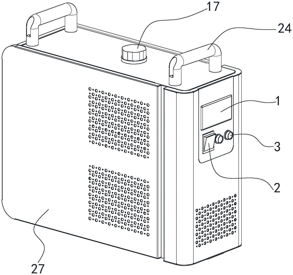
图1为本实用新型的结构示意图;Fig. 1 is the structural representation of the utility model;
图2为本实用新型的结构示意图;Fig. 2 is the structural representation of the utility model;
图3为本实用新型的内部结构示意图;Fig. 3 is the internal structure schematic diagram of the utility model;
图4为本实用新型的内部结构示意图;4 is a schematic diagram of the internal structure of the utility model;
图5为本实用新型的爆炸结构示意图;Fig. 5 is the exploded structure schematic diagram of the present utility model;
图6为本实用新型的A部分局部放大示意图;Fig. 6 is the partial enlarged schematic diagram of A part of the present utility model;
图中:1、控制面板;2、开关;3、指示灯;4、制冷控制器;5、继电器;6、进水接头;7、出水接头;8、断水保护接头;9、电源线接头;10、水流保护器;11、散热风扇开口;12、排水口;13、防护网;14、散热风扇;15、冷凝器;16、水箱;17、水箱进水口;18、压缩机;19、蒸发器;20、干燥过滤器;21、节流器;22、水泵;23、液位观察口;24、把手;25、蜂鸣器;26、侧板一;27、侧板二。In the figure: 1. Control panel; 2. Switch; 3. Indicator light; 4. Refrigeration controller; 5. Relay; 6. Water inlet connector; 7. Water outlet connector; 8. Water-break protection connector; 9. Power cord connector; 10, water flow protector; 11, cooling fan opening; 12, water outlet; 13, protective net; 14, cooling fan; 15, condenser; 16, water tank; 17, water tank inlet; 18, compressor; 19,
具体实施方式Detailed ways
下面通过具体实施方式对本实用新型技术方案作进一步解释说明。The technical solution of the present utility model will be further explained below through specific embodiments.
实施例1Example 1
参见附图,本实用新型提供了一种激光水冷机,包括有壳体,壳体前部上侧安装有控制面板1,控制面板1下部安装有开关2和指示灯3,控制面板1下部内侧安装有温控器为制冷控制器4,制冷控制器4旁边安装有继电器5;所述的制冷控制器旁边还安装有蜂鸣器25。Referring to the drawings, the utility model provides a laser water cooler, which includes a casing, a
壳体后部上侧安装有进水接头6、出水接头7、断水保护接头8和电源线接头9,出水接头7位于壳体内侧的部分连接有水流保护器10,可采用型号为:Flow switch DC:130V10W;在水管中无水流时,通过继电器使蜂鸣器响起与指示灯中的报警灯亮起;提醒工作人员;A
壳体后部开设有散热风扇开口11和排水口12,所述的散热风扇开口11数量为2;散热风扇开口11外侧安装有防护网13,内侧安装有散热风扇14,散热风扇14内侧安装有冷凝器15;A cooling fan opening 11 and a
壳体内部上侧安装有水箱16,壳体上部开设有通孔,通孔内穿过有水箱进水口17,水箱16和排水口12之间通过水管连接,壳体内部下侧安装有压缩机18,压缩机18和冷凝器15之间安装有蒸发器19;压缩机18、冷凝器15、干燥过滤器20、节流器21、蒸发器19的介质通道之间通过介质管串联连接构成循环回路,介质管内填充有制冷剂;所述的制冷剂为R-134a。A
进水接头6、水箱16、水泵22、蒸发器19的水通道、水流保护器10之间通过水管串联连接。所述的壳体前部下侧设置有多个透气孔。所述的壳体上部两侧安装有2个把手。所述的壳体两侧为侧板一26和侧板二27,其中侧板一26上部设置有长条的液位观察口23。所述的壳体侧板一26和侧板二27上开设有多个透气孔。The
Claims (10)
Priority Applications (1)
| Application Number | Priority Date | Filing Date | Title |
|---|---|---|---|
| CN202123114435.3U CN216251594U (en) | 2021-12-11 | 2021-12-11 | Laser water cooling machine |
Applications Claiming Priority (1)
| Application Number | Priority Date | Filing Date | Title |
|---|---|---|---|
| CN202123114435.3U CN216251594U (en) | 2021-12-11 | 2021-12-11 | Laser water cooling machine |
Publications (1)
| Publication Number | Publication Date |
|---|---|
| CN216251594U true CN216251594U (en) | 2022-04-08 |
Family
ID=80962070
Family Applications (1)
| Application Number | Title | Priority Date | Filing Date |
|---|---|---|---|
| CN202123114435.3U Expired - Fee Related CN216251594U (en) | 2021-12-11 | 2021-12-11 | Laser water cooling machine |
Country Status (1)
| Country | Link |
|---|---|
| CN (1) | CN216251594U (en) |
Cited By (1)
| Publication number | Priority date | Publication date | Assignee | Title |
|---|---|---|---|---|
| CN116811695A (en) * | 2023-04-25 | 2023-09-29 | 广州卫富科技开发有限公司 | A refrigeration host |
-
2021
- 2021-12-11 CN CN202123114435.3U patent/CN216251594U/en not_active Expired - Fee Related
Cited By (1)
| Publication number | Priority date | Publication date | Assignee | Title |
|---|---|---|---|---|
| CN116811695A (en) * | 2023-04-25 | 2023-09-29 | 广州卫富科技开发有限公司 | A refrigeration host |
Similar Documents
| Publication | Publication Date | Title |
|---|---|---|
| CN213901575U (en) | Chillers and Energy Storage Systems | |
| CN104640421A (en) | Air conditioning unit | |
| CN221448921U (en) | Cooling system for air-liquid mixed cooling and miniature data center | |
| CN211119798U (en) | Air conditioner air can automated inspection new trend system oil smoke all-in-one | |
| CN104703448A (en) | Server cabinet cooling system with combined gate-type cold water heat exchange device and liquid cooling device | |
| CN116075108A (en) | Internal and external cycle adjustable refrigeration system and data center | |
| CN103900217A (en) | Cooling control method, device and system for modular data center | |
| CN209768093U (en) | Liquid cooling system based on evaporative cooling technology | |
| CN221403319U (en) | Indirect evaporative cooling air conditioning unit | |
| CN116683264B (en) | Solid laser convenient to cool down | |
| CN102927647B (en) | A kind of base station air conditioner | |
| CN218006860U (en) | Liquid cooling equipment, integrated cabinet and container | |
| CN111256213A (en) | A kitchen cleanable air-conditioning air energy intelligent detection fresh air system integrated cabinet | |
| CN202521767U (en) | Evaporative and electronic dual refrigeration cooling fan | |
| CN217604474U (en) | Energy-saving air-cooled water chiller | |
| CN101896045A (en) | Natural heat dissipation outdoor cabinet | |
| CN205666444U (en) | Power distribution cabinet with dual heat dissipation function | |
| CN205505208U (en) | Embedded energy -conserving air conditioner with rack integration | |
| CN211953111U (en) | A water-cooled central air-conditioning unit | |
| CN104422017A (en) | Active heat pipe back plate cooling system | |
| CN221991945U (en) | A dehumidifier with good heat dissipation effect | |
| CN202232014U (en) | Container data center cooling device | |
| CN116096028A (en) | Double rack formula data center and refrigerating system | |
| CN222380657U (en) | Energy storage container with ventilation system | |
| CN215073596U (en) | Indirect evaporative cooling air conditioning unit of data center |
Legal Events
| Date | Code | Title | Description |
|---|---|---|---|
| GR01 | Patent grant | ||
| GR01 | Patent grant | ||
| CF01 | Termination of patent right due to non-payment of annual fee |
Granted publication date: 20220408 |
|
| CF01 | Termination of patent right due to non-payment of annual fee |