CN216246360U - Topographic surveying and mapping device for architectural design - Google Patents
Topographic surveying and mapping device for architectural design Download PDFInfo
- Publication number
- CN216246360U CN216246360U CN202122871303.9U CN202122871303U CN216246360U CN 216246360 U CN216246360 U CN 216246360U CN 202122871303 U CN202122871303 U CN 202122871303U CN 216246360 U CN216246360 U CN 216246360U
- Authority
- CN
- China
- Prior art keywords
- surveying
- protection box
- architectural design
- box body
- mapping device
- Prior art date
- Legal status (The legal status is an assumption and is not a legal conclusion. Google has not performed a legal analysis and makes no representation as to the accuracy of the status listed.)
- Active
Links
Images


Landscapes
- Buildings Adapted To Withstand Abnormal External Influences (AREA)
Abstract
The utility model relates to a topographic surveying and mapping device for architectural design, which comprises a protective box body, wherein a damping plate is arranged in the inner cavity of the protective box body, a surveying and mapping instrument is arranged on the damping plate, a movable plate is hinged to the right side of the protective box body, the right side of the movable plate is connected with the bottom of the protective box body through an inclined strut, a drawing table is arranged on the left side of the movable plate, a triangular support is arranged at the bottom of the protective box body, the surveying and mapping instrument is placed in the protective box body, is convenient for personnel to carry the surveying and mapping instrument outdoors, has an effective protective effect, avoids colliding with other objects, can effectively play a damping role, can play a buffering role for the surveying and mapping instrument during transportation, avoids the damage of the surveying and mapping instrument, can carry out surveying and mapping after the protective box body is connected with the triangular support during surveying and mapping, and can be turned outwards by the movable plate and horizontally supported by the inclined strut, so that the personnel can conveniently draw and map at the same time, The record and the use are more convenient.
Description
Technical Field
The utility model relates to a topographic surveying and mapping device for architectural design, and belongs to the technical field of topographic surveying and mapping devices.
Background
Topographic mapping refers to the operation of mapping a topographic map, namely, the projection positions and elevations of the ground features on the surface of the earth and the terrain on a horizontal plane are measured, the measured positions and elevations are reduced according to a certain proportion, and symbols and marks are used for drawing the topographic map; before building construction, topographic surveying is an indispensable step, and when building topographic surveying is carried out, a surveying instrument is generally placed on a surveying device for surveying; but survey and drawing is all worked in the open air, just need take surveying and drawing places with instruments such as surveying instrument and support, on the road can lead to its and other objects to collide because of jolting on the road unavoidably, can cause the damage to surveying instrument in the long term, carry out the survey and drawing during operation moreover, often need carry out the record of on-the-spot drawing or data, and current surveying and drawing device does not have the workstation for drawing and record are extremely inconvenient.
SUMMERY OF THE UTILITY MODEL
The utility model aims to provide a topographic surveying and mapping device for architectural design, wherein a surveying and mapping instrument is placed in a protective box body, so that the topographic surveying and mapping instrument can be conveniently carried outdoors by personnel, a protective effect can be effectively achieved, collision with other objects is avoided, a damping plate can effectively play a damping role, the surveying and mapping instrument can be buffered during transportation, and damage of the surveying and mapping instrument is avoided.
In order to achieve the purpose, the utility model provides the following technical scheme: the utility model provides a topographic survey and drawing device for architectural design, includes the protection box, protection box inner chamber is equipped with the shock attenuation board, be equipped with the surveying instrument on the shock attenuation board, protection box right side articulates there is the fly leaf, the fly leaf right side is connected with protection bottom of the case portion through the diagonal brace, the fly leaf left side is equipped with the drawing bench, protection bottom of the case portion is equipped with the A-frame.
Further, the fixed handle that is equipped with in protection box top, and with the fixed viewing aperture that is equipped with in surveying instrument corresponding position, the fixed plate that is equipped with of protection box inner wall, evenly be connected through damping spring between fixed plate and the shock attenuation board, fixed plate, shock attenuation board are cavity ring-type.
Further, the fixed connecting seat that is equipped with in surveying instrument bottom, the shock attenuation board is run through to the connecting seat bottom, surveying instrument top and protection box inner chamber top all are equipped with the elastic plate, and the elastic plate is the arc setting.
Furthermore, a sliding groove is fixedly formed in the right side of the movable plate, a sliding rod is arranged in the sliding groove in a sliding mode, and two ends of the inclined strut are hinged to the sliding rod and the protective box body respectively.
Furthermore, a mounting seat is fixedly arranged at the top of the triangular support, a fixing rod is fixedly arranged on the mounting seat, the top end of the fixing rod penetrates through the protective box body and is embedded into the connecting seat, limiting grooves are symmetrically formed in the fixing rod, and limiting lugs are arranged on the inner wall of the connecting seat and correspond to the limiting grooves.
Furthermore, drawing table both sides all rotate and are equipped with the fiber container, the winding has the drawing paper on the fiber container, and the drawing paper sets up on the drawing table surface.
The utility model has the beneficial effects that:
1. by arranging the damping plate, the surveying instrument is placed in the protective box body, so that the protective effect can be effectively achieved, collision with other objects can be avoided, meanwhile, the damping plate can effectively achieve a damping effect, and the surveying instrument can be buffered during transportation, so that the damage of the surveying instrument is avoided;
2. through setting up the fly leaf, in the survey and drawing, the fly leaf can outwards be turned up, supports its level through the diagonal brace to make things convenient for personnel to paint, the record in the survey and drawing, it is more convenient to use.
Drawings
The accompanying drawings, which are included to provide a further understanding of the utility model and are incorporated in and constitute a part of this specification, illustrate embodiments of the utility model and together with the description serve to explain the utility model without limiting the utility model.
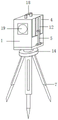
FIG. 1 is an overall block diagram of a topographic mapping device for architectural design in accordance with the present invention;
FIG. 2 is a cross-sectional view of a protective housing of a topographical mapping device for architectural design in accordance with the present invention;
FIG. 3 is a schematic diagram of a movable plate structure of a topographic surveying and mapping device for architectural design in accordance with the present invention;
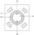
FIG. 4 is a schematic top cross-sectional view of a shock absorbing plate of a topographical mapping device for architectural design in accordance with the present invention;
reference numbers in the figures: 1. a protective box body; 2. a damper plate; 3. a surveying instrument; 4. a movable plate; 5. A diagonal brace; 6. a drawing table; 7. a triangular bracket; 8. a fixing plate; 9. a damping spring; 10. A connecting seat; 11. an elastic plate; 12. a chute; 13. a slide bar; 14. a mounting seat; 15. fixing the rod; 16. a paper winding drum; 17. drawing paper; 18. a handle; 19. a viewing port; 20. a limiting groove; 21. and a limiting bump.
Detailed Description
The preferred embodiments of the present invention will be described in conjunction with the accompanying drawings, and it will be understood that they are described herein for the purpose of illustration and explanation and not limitation.
In the description of the present invention, it should be noted that the terms "upper", "lower", "inner", "outer", "front", "rear", "both ends", "one end", "the other end", and the like indicate orientations or positional relationships based on those shown in the drawings, and are only for convenience of description and simplicity of description, but do not indicate or imply that the referred device or element must have a specific orientation, be constructed in a specific orientation, and be operated, and thus, should not be construed as limiting the present invention. Furthermore, the terms "first" and "second" are used for descriptive purposes only and are not to be construed as indicating or implying relative importance.
Referring to fig. 1-4, the present invention provides a technical solution: the utility model provides a topographic survey and drawing device for architectural design, includes protection box 1, 1 inner chamber of protection box is equipped with shock attenuation board 2, be equipped with surveying instrument 3 on the shock attenuation board 2, 1 right side of protection box articulates there is fly leaf 4, fly leaf 4 right side is connected with 1 bottom of protection box through diagonal brace 5, 4 left sides of fly leaf are equipped with drawing platform 6, 1 bottom of protection box is equipped with A-frame 7.
Specifically, as shown in fig. 1 and 2, 1 top of protection box is fixed and is equipped with handle 18, and with 3 corresponding fixed being equipped with viewing aperture 19 of surveying instrument, 1 inner wall of protection box is fixed and is equipped with fixed plate 8, evenly be connected through damping spring 9 between fixed plate 8 and the damping plate 2, fixed plate 8, damping plate 2 are cavity ring-type, make things convenient for placing of surveying instrument 3, 3 fixed being equipped with connecting seats 10 in bottom of surveying instrument, damping plate 2 is run through to connecting seat 10 bottom, 3 tops of surveying instrument all are equipped with elastic plate 11 with 1 inner chamber top of protection box, and elastic plate 11 is the arc setting, can fix 3 tops of surveying instrument, prevent to rock.
Specifically, as shown in fig. 3, 4 right sides of fly leaf are fixed and are equipped with spout 12, it is equipped with slide bar 13 to slide in spout 12, 5 both ends of diagonal brace are articulated with slide bar 13, protection box 1 respectively, can let slide bar 13 slide when using to let fly leaf 4 present the horizontality, conveniently draw, drawing table 6 both sides are all rotated and are equipped with a paper roll 16, the winding has drawing paper 17 on the paper roll 16, and drawing paper 17 sets up on drawing table 6 is surperficial, and the drawing of being convenient for is smooth to be spread on drawing table 6, and it is more convenient to use.
Specifically, as shown in fig. 4, the fixed mount pad 14 that is equipped with in tripod 7 top, the fixed dead lever 15 that is equipped with on the mount pad 14, the dead lever 15 top is run through in protection box 1 embedding connecting seat 10, spacing groove 20 has been seted up to the symmetry on the dead lever 15, connecting seat 10 inner wall is equipped with spacing lug 21 with spacing groove 20 corresponding position, is being connected the back with tripod 7, and dead lever 15 gets into in connecting seat 10, and then damper plate 2 is not having the supporting role, guarantees its stability when surveying and mapping.
The working principle of the utility model is as follows: place the surveying instrument in protection box 1, can effectively play the protective effect, avoid colliding with other objects, shock attenuation board 2 can effectively play the cushioning effect simultaneously, can play the cushioning effect to surveying instrument 3 when the transportation, avoid it to damage, when using, will protect box 1 and the triangular support 7 back of being connected, let dead lever 15 get into in the connecting seat 10, then shock attenuation board 2 is not having the supporting role, guarantee its stability when the survey and drawing, simultaneously fly leaf 4 can outwards turn up, support its level through diagonal brace 5, thereby make things convenient for personnel to paint, the record, it is more convenient to use.
The above embodiments are preferred embodiments of the present invention, and those skilled in the art can make variations and modifications to the above embodiments, therefore, the present invention is not limited to the above embodiments, and any obvious improvements, substitutions or modifications made by those skilled in the art based on the present invention are within the protection scope of the present invention.
Claims (6)
1. The utility model provides a topographic surveying and mapping device for architectural design, includes protection box (1), its characterized in that: protection box (1) inner chamber is equipped with shock attenuation board (2), be equipped with surveying instrument (3) on shock attenuation board (2), protection box (1) right side articulates there is fly leaf (4), fly leaf (4) right side is connected bottom protection box (1) through diagonal brace (5), fly leaf (4) left side is equipped with drawing platform (6), protection box (1) bottom is equipped with A-frame (7).
2. A topographic mapping device for architectural design according to claim 1, wherein: protection box (1) top is fixed to be equipped with handle (18), and with surveying instrument (3) corresponding fixed position be equipped with viewing aperture (19), protection box (1) inner wall is fixed to be equipped with fixed plate (8), evenly be connected through damping spring (9) between fixed plate (8) and damping plate (2), fixed plate (8), damping plate (2) are the cavity cyclic annular.
3. A topographic mapping device for architectural design according to claim 2, wherein: surveying instrument (3) bottom is fixed and is equipped with connecting seat (10), shock attenuation board (2) are run through to connecting seat (10) bottom, surveying instrument (3) top all is equipped with elastic plate (11) with protection box (1) inner chamber top, and elastic plate (11) are the arc setting.
4. A topographic mapping device for architectural design according to claim 3, wherein: the right side of the movable plate (4) is fixedly provided with a sliding groove (12), a sliding rod (13) is arranged in the sliding groove (12) in a sliding mode, and two ends of the inclined stay bar (5) are hinged to the sliding rod (13) and the protective box body (1) respectively.
5. A topographic mapping device for architectural design according to claim 4, wherein: the triangular support is characterized in that a mounting seat (14) is fixedly arranged at the top of the triangular support (7), a fixing rod (15) is fixedly arranged on the mounting seat (14), the top end of the fixing rod (15) penetrates through the protective box body (1) and is embedded into the connecting seat (10), limiting grooves (20) are symmetrically formed in the fixing rod (15), and limiting convex blocks (21) are arranged on the inner wall of the connecting seat (10) and correspond to the limiting grooves (20).
6. A topographic mapping device for architectural design according to claim 5, wherein: drawing platform (6) both sides all rotate and are equipped with a scroll section of thick bamboo (16), the winding has drawing paper (17) on a scroll section of thick bamboo (16), and drawing paper (17) set up on drawing platform (6) surface.
Priority Applications (1)
| Application Number | Priority Date | Filing Date | Title |
|---|---|---|---|
| CN202122871303.9U CN216246360U (en) | 2021-11-22 | 2021-11-22 | Topographic surveying and mapping device for architectural design |
Applications Claiming Priority (1)
| Application Number | Priority Date | Filing Date | Title |
|---|---|---|---|
| CN202122871303.9U CN216246360U (en) | 2021-11-22 | 2021-11-22 | Topographic surveying and mapping device for architectural design |
Publications (1)
| Publication Number | Publication Date |
|---|---|
| CN216246360U true CN216246360U (en) | 2022-04-08 |
Family
ID=80954585
Family Applications (1)
| Application Number | Title | Priority Date | Filing Date |
|---|---|---|---|
| CN202122871303.9U Active CN216246360U (en) | 2021-11-22 | 2021-11-22 | Topographic surveying and mapping device for architectural design |
Country Status (1)
| Country | Link |
|---|---|
| CN (1) | CN216246360U (en) |
-
2021
- 2021-11-22 CN CN202122871303.9U patent/CN216246360U/en active Active
Similar Documents
| Publication | Publication Date | Title |
|---|---|---|
| CN207407885U (en) | A kind of supporting mechanism for geography information measuring instrument | |
| CN205718949U (en) | A kind of civil engineering measurement apparatus | |
| CN208751565U (en) | A kind of dismountable fixed device of surveying instrument | |
| CN208025104U (en) | A kind of engineering mapping bracket for laser range finder | |
| CN208333466U (en) | A kind of civil engineering of high stability commonly uses surveying instrument mounting base | |
| CN118602228A (en) | A surveying and mapping instrument bracket with adjustable surveying and mapping height | |
| CN208443380U (en) | A kind of theodolite | |
| CN206369554U (en) | A kind of mapping support for being adapted to field mapping | |
| CN215706057U (en) | A vehicle-mounted measuring device for land and space planning | |
| CN213576373U (en) | Town and country planning is with surveying instrument that possesses anticollision shock-absorbing function | |
| CN221974912U (en) | Surveying and mapping frame for building construction | |
| CN209485340U (en) | A kind of engineering survey level support device | |
| CN211954162U (en) | Combined on-site surveying and mapping device for construction engineering cost | |
| CN209587347U (en) | A kind of concrete pump tube support device | |
| CN214663377U (en) | Leveling device with overturn-preventing structure for bridge road construction | |
| CN220688486U (en) | Village planning field survey equipment | |
| CN222599828U (en) | Portable laser range finder | |
| CN215338325U (en) | An external protective structure for an outdoor geodetic height measuring instrument | |
| CN213361676U (en) | Geographic information system data field processing working equipment and fixing structure thereof | |
| CN221725234U (en) | A planning and measuring device for architectural design | |
| CN214929072U (en) | Anti-impact type new energy charging pile capable of being powered by solar energy | |
| CN215944889U (en) | Building completion measuring device based on unmanned aerial vehicle | |
| CN211203379U (en) | Mapping support that practicality is strong and crashworthiness is good | |
| CN218935872U (en) | Surveying instrument for assisting engineering management | |
| CN221922954U (en) | Base is used in survey and drawing appearance installation |
Legal Events
| Date | Code | Title | Description |
|---|---|---|---|
| GR01 | Patent grant | ||
| GR01 | Patent grant |