Bearing platform assembly structure for building backfill foundation pit
Technical Field
The application relates to the technical field of pile foundation backfill, in particular to a bearing platform assembly structure for a building backfill foundation pit.
Background
The pile foundation is the foundation of the building, the pile foundation generally is made up of foundation pile and pile cap connected on the top of foundation pile, in the course of installation of pile foundation, usually bury the foundation pile all into the soil body, the foundation pile passes the soft soil layer and accepts and stabilizes in the hard soil layer, the pile cap contacts with surface layer of the soil body, the pile foundation relies on the deep firm soil layer, the pile foundation has good compressive capacity and antidumping ability, has improved the stability of the high-rise building to a certain extent.
Because the lower soil density is higher than the ground soil density and the bearing capacity of the lower soil is larger, in order to place the center of gravity of the building footing on a harder soil foundation, workers usually dig a foundation pit on the peripheral wall of a foundation pile, and the foundation pit is arranged to improve the stability of the building, so that the building cannot be settled due to insufficient bearing capacity of the soil foundation.
In some construction schemes, a wall body is often built with bricks on the peripheral wall of the pile foundation, the pile foundation is surrounded, soil is filled outside the wall body, so that the wall body surrounding the pile foundation forms a foundation pit, the soil body near the foundation pit is compacted by a soil filling and compacting mode, and then the foundation is backfilled with concrete, so as to improve the foundation bearing capacity of the building, wherein the backfilling construction process generally comprises the following steps: cleaning the floating soil on the four walls of the foundation pit, performing on-site survey, tamping to a cushion layer, backfilling a pile foundation, removing sundries, removing plowed soil, rolling base soil, backfilling to a bearing platform, and backfilling to the top of the bearing platform.
However, the operation of building the wall with bricks makes it take a long time for the foundation pit to be formed, and simultaneously, the operation of building the wall with bricks increases the workload of workers.
SUMMERY OF THE UTILITY MODEL
In order to improve the speed that the foundation ditch was built, this application provides building backfill cushion cap assembly structure for foundation ditch, can make the precast concrete board install conveniently, can strengthen the compressive property who backfills the structure.
The application provides a building is backfilled cushion cap assembly structure for foundation ditch adopts following technical scheme:
building is backfilled cushion cap assembly structure for foundation ditch, including the pile foundation, install polylith light prefabricated plate, polylith on the ground of pile foundation top week side the light prefabricated plate will pile foundation top cushion cap encloses and establishes, and is adjacent fix through fixed reinforcing bar between the light prefabricated plate.
Through adopting above-mentioned technical scheme, the light precast slab can assemble together under the effect of fixed reinforcing bar conveniently to, under the cooperation of light precast slab and fixed reinforcing bar, can make the perisporium of pile foundation form the foundation ditch fast, saved the required time of staff out of the foundation ditch with the brickwork pile, improved the speed that the foundation ditch was built effectively.
Preferably, the light prefabricated plates adopt four blocks, and after the four blocks are connected through fixed steel bars, inner wall spaces formed by the four blocks are rectangular.
By adopting the technical scheme, the inner wall space formed by the light precast slab is rectangular, so that the stability of the building is improved to a certain extent.
Preferably, the two adjacent light prefabricated panels are arranged in a T-shaped staggered manner.
By adopting the technical scheme, the two adjacent light prefabricated plates are arranged in a staggered manner, so that the stability of the foundation pit can be improved.
Preferably, an elastic connecting seat and a supporting column are arranged between the two opposite light prefabricated plates, the supporting column is installed between the two opposite light prefabricated plates, the elastic connecting seats are installed at two ends of the supporting column, one side, close to the light prefabricated plates, of each elastic connecting seat is abutted against the corresponding light prefabricated plate, and two ends of the supporting column are abutted against two opposite side faces of the elastic connecting seats respectively.
By adopting the technical scheme, the compression resistance between the light precast slabs is effectively enhanced under the matching action of the elastic connecting seat and the supporting column.
Preferably, the ground on the peripheral side of the pile foundation is provided with a pit slot, and the light precast slab is inserted in the pit slot.
By adopting the technical scheme, the light prefabricated slab can be easily inserted into the soil body by arranging the pit groove.
Preferably, the middle part of one side of the light precast slab, which is close to the soil body, is provided with a groove.
By adopting the technical scheme, when the light prefabricated slab is embedded into a soil body, soil can enter the middle part of the groove, so that the elastic resistance of the light prefabricated slab can be improved, and the light prefabricated slab can be stably arranged on the ground.
Preferably, the pile foundation includes: a foundation pile group buried in the soil body; and the bearing platform is arranged on the top surface of the foundation pile group.
By adopting the technical scheme, the foundation pile group is buried in the soil body, the downward grabbing force of the pile foundation is enhanced, the pile foundation is stably installed in the soil body, the bearing platform is arranged to uniformly distribute the load on each foundation pile, and the stress of the pile foundation is balanced.
Preferably, the top surface of the bearing platform is provided with a reinforcing steel bar layer.
By adopting the technical scheme, the arrangement of the reinforcing steel layer enables the bearing platform to be stably anchored in the soil body, and the stability of the pile foundation is improved to a certain extent.
Preferably, the pile foundation is a low-bearing-platform pile foundation.
By adopting the technical scheme, the low pile cap pile foundation has good pressure resistance and anti-overturning capability, and the stability of a building can be effectively improved.
In summary, the present application includes at least one of the following beneficial technical effects:
the light precast slabs can be conveniently assembled together under the action of the fixed reinforcing steel bars, and the peripheral walls of the pile foundations can quickly form a foundation pit under the matching of the light precast slabs and the fixed reinforcing steel bars, so that the time required by workers to pile the foundation pit with bricks is saved, and the speed of building the foundation pit is effectively improved;
when the light prefabricated slab is embedded into a soil body, soil can enter the middle part of the groove, so that the elastic resistance of the light prefabricated slab can be improved, and the light prefabricated slab can be stably installed on the ground;
the low pile cap pile foundation has good pressure resistance and anti-overturning capability, and can effectively improve the stability of the building.
Drawings
Fig. 1 is a schematic overall structure diagram in the embodiment of the present application.
Fig. 2 is a sectional view of fig. 1.
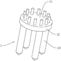
Fig. 3 is a schematic structural diagram of a pile foundation in the embodiment of the present application.
Description of reference numerals: 11. a soft soil layer; 12. a hard soil layer; 2. a pile foundation; 21. a reinforcing steel bar layer; 22. a bearing platform; 23. foundation piles; 4. a foundation pit; 41. a light prefabricated slab; 42. fixing the steel bars; 43. a groove; 44. a pit; 5. supporting a pillar; 6. an elastic connecting seat.
Detailed Description
In order to make the purpose, technical solution and advantages of the present application more clear, the present application is further described in detail below with reference to fig. 1-3 and the embodiments.
The embodiment of the application discloses building backfill foundation ditch is with cushion cap assembly structure.
Referring to fig. 1 and 2, the bearing platform assembly structure for the backfill foundation pit of the building comprises a pile foundation 2, in the embodiment of the application, the pile foundation 2 (refer to fig. 3) comprises a foundation pile group and a bearing platform 22, the bearing platform 22 is installed on the top surface of the foundation pile group, the top view of the bearing platform 22 is circular, the foundation pile group comprises four foundation piles 23, the foundation piles 23 are completely embedded in a soil body, the foundation piles 23 penetrate through a soft soil layer 11 and are stably supported in a hard soil layer 12, in the real-time embodiment of the application, the pile foundation 2 is a low bearing platform pile foundation, namely, the bottom surface of the bearing platform 22 is in contact with the surface layer of the soil body, and the foundation piles 23 are completely embedded in the soil body, so that the pile foundation 2 has good pressure resistance and anti-overturning capability, and the stability of the building can be improved.
The peripheral side ground of the pile foundation 2 is provided with a pit 44, the pit 44 is provided with light weight prefabricated panels 41, the light weight prefabricated panels 41 are inserted and fixed in the pit 44, in the embodiment of the application, four light weight prefabricated panels 41 are provided, two opposite light weight prefabricated panels 41 are symmetrically arranged, two adjacent light weight prefabricated panels 41 are arranged in a T-shaped staggered manner, a fixed steel bar 42 is arranged between the two adjacent light weight prefabricated panels 41, and the solid steel bar penetrates through the long side wall of one light weight prefabricated panel 41 and is fixed on the short side wall of the adjacent light weight prefabricated panel 41.
Referring to fig. 1, a foundation pit 4 is formed after four light prefabricated panels 41 are assembled, a top view of the foundation pit 4 is rectangular, sand is generally filled and backfilled on the peripheral wall of the foundation pit 4 before a pile foundation 2 is backfilled, in the process, workers need to fill and backfill the uneven part of the peripheral wall of the foundation pit 4 and tamp the backfilled sand, so that the peripheral wall of the foundation pit 4 is leveled, in order to reduce the collapse phenomenon of the light prefabricated panels 41 during filling and backfilling of the sand, grooves 43 are formed in the bottom surface of one side, close to a soil body, of the light prefabricated panels 41, and after the grooves 43 are embedded into the soil layer, silt can fill the grooves 43, so that the light prefabricated panels 41 have good elastic resistance when embedded into the soil body, and the light prefabricated panels 41 can be stably installed on the ground.
In order to make the light prefabricated panels 41 more stably installed on the ground, an elastic connecting base 6 and a supporting column 5 are arranged between two opposite light prefabricated panels 41, the side surface of the elastic connecting base 6 is rectangular, the supporting column 5 is cylindrical, in the embodiment of the application, the elastic connecting base 6 is a rubber base, two elastic connecting bases 6 and one supporting column 5 are arranged between two opposite light prefabricated panels 41, a worker firstly fixes the elastic connecting base 6 on two opposite side walls of the supporting column 5, then two opposite side surfaces of the elastic connecting base 6 are abutted against two opposite side walls of the light prefabricated panels 41, the elastic connecting base 6 is not easy to fall on the ground under the mutual extrusion of the supporting column 5 and the light prefabricated panels 41, and in addition, the arrangement of the elastic connecting base 6 and the supporting column 5 provides a supporting force when sand is backfilled on the peripheral wall of the foundation pit 4.
The reinforcement layer 21 is arranged on the top surface of the pile foundation 22, the number of the reinforcements in the reinforcement layer 21 is determined according to the situation, and the reinforcements in the reinforcement layer 21 are uniformly distributed on the pile foundation 22, so that the stability of the pile foundation 2 can be improved.
The implementation principle of the bearing platform assembly structure for the building backfill foundation pit is as follows:
the worker buries the foundation pile 23 in the soil layer in the pile foundation 2 to make the bottom surface of the bearing platform 22 contact with the surface layer of the soil body, the reinforcing steel bar layer 21 on the bearing platform 22 is exposed on the ground, the four light prefabricated plates 41 are alternately arranged on the peripheral wall of the pile foundation 2, the solid reinforcing steel bars penetrate through the long side wall of one light prefabricated plate 41 to be fixed on the short side wall of the adjacent light prefabricated plate 41, and under the action of the elastic connecting seat 6 and the supporting columns 5, the light prefabricated plates 41 are not easy to be pushed down by the pushing force of backfilling sand, so that the concrete prefabricated plates can be conveniently installed, and the compression resistance of a backfilling structure can be enhanced.
The above are all preferred embodiments of the present application, and the present embodiment is only explained for the present application, and the protection scope of the present application is not limited by this, so: all equivalent changes made according to the structure, shape and principle of the present application shall be covered by the protection scope of the present application.