SUMMERY OF THE UTILITY MODEL
The utility model provides a lifting type crane trolley capable of horizontally carrying heavy objects, and aims to solve the problems that manpower is consumed and efficiency is low when the heavy objects are manually supported for transportation at present.
The utility model is realized in such a way that the lifting type crane trolley capable of horizontally carrying heavy objects comprises an underframe, wherein at least two walking mechanisms are arranged on the underframe, and each walking mechanism is connected with the underframe; a support frame is arranged above the bottom frame, the support frame is connected with the bottom frame through an upright post, a first hydraulic cylinder is vertically arranged inside the support frame, and the first hydraulic cylinder is fixedly connected with the support frame; the support frame is characterized in that a connecting frame is arranged above the support frame, an output shaft of the first hydraulic cylinder is fixedly connected with the connecting frame, and the connecting frame is connected with the support frame in a sliding mode.
Preferably, the top of the underframe is also provided with a fixing plate; the fixing plate is L-shaped; and a second hydraulic cylinder is arranged on the side wall of the fixed plate.
Preferably, a sliding plate is arranged on the fixed plate; and the output shaft of the second hydraulic cylinder is fixedly connected with the sliding plate.
Preferably, the bottoms of the two ends of the connecting frame are provided with guide posts; each guide post penetrates through the support frame and extends downwards.
Preferably, the walking mechanism comprises a cylinder; the cylinder is positioned on the side wall of the bottom frame and is fixedly connected with the bottom frame; a telescopic rod is vertically arranged in the barrel; one end of the telescopic rod is fixedly connected with the barrel, and the other end of the telescopic rod is provided with a travelling wheel.
Preferably, the outer wall of the telescopic rod is sleeved with a spring; one end of the spring is fixedly connected with the cylinder body, and the other end of the spring is connected with the travelling wheel.
Preferably, the connecting frame has a placing groove inside.
Preferably, the fixing plate is a stainless steel plate; the sliding plate is a steel plate.
Compared with the prior art, the utility model has the beneficial effects that:
according to the utility model, the first hydraulic cylinder is arranged, when a user opens the first hydraulic cylinder, the output shaft of the first hydraulic cylinder drives the connecting frame to move in the vertical direction until the connecting frame is contacted with the heavy object, the heavy object is installed on the connecting frame through the bolt at the moment, and finally the heavy object is driven to descend through the first hydraulic cylinder until the connecting frame is contacted with the supporting frame, so that the first hydraulic cylinder and the upright post simultaneously support the heavy object.
According to the utility model, by arranging the guide post, when the output shaft of the first hydraulic cylinder drives the connecting frame to move in the vertical direction, the connecting frame slides in the supporting frame through the guide post, so that the guide is provided for the movement of the connecting frame, and the horizontal deviation of the connecting frame in the vertical direction is avoided.
Detailed Description
In order to make the objects, technical solutions and advantages of the present invention more apparent, the present invention is described in further detail below with reference to the accompanying drawings and embodiments. It should be understood that the specific embodiments described herein are merely illustrative of the utility model and are not intended to limit the utility model.
In the description of the present invention, it should be noted that, unless otherwise explicitly specified or limited, the terms "mounted," "disposed," "sleeved/connected," "connected," and the like are to be construed broadly, e.g., "connected," which may be fixedly connected, detachably connected, or integrally connected; can be mechanically or electrically connected; they may be connected directly or indirectly through intervening media, or may be interconnected between two elements. The specific meanings of the above terms in the present invention can be understood in specific cases to those skilled in the art.
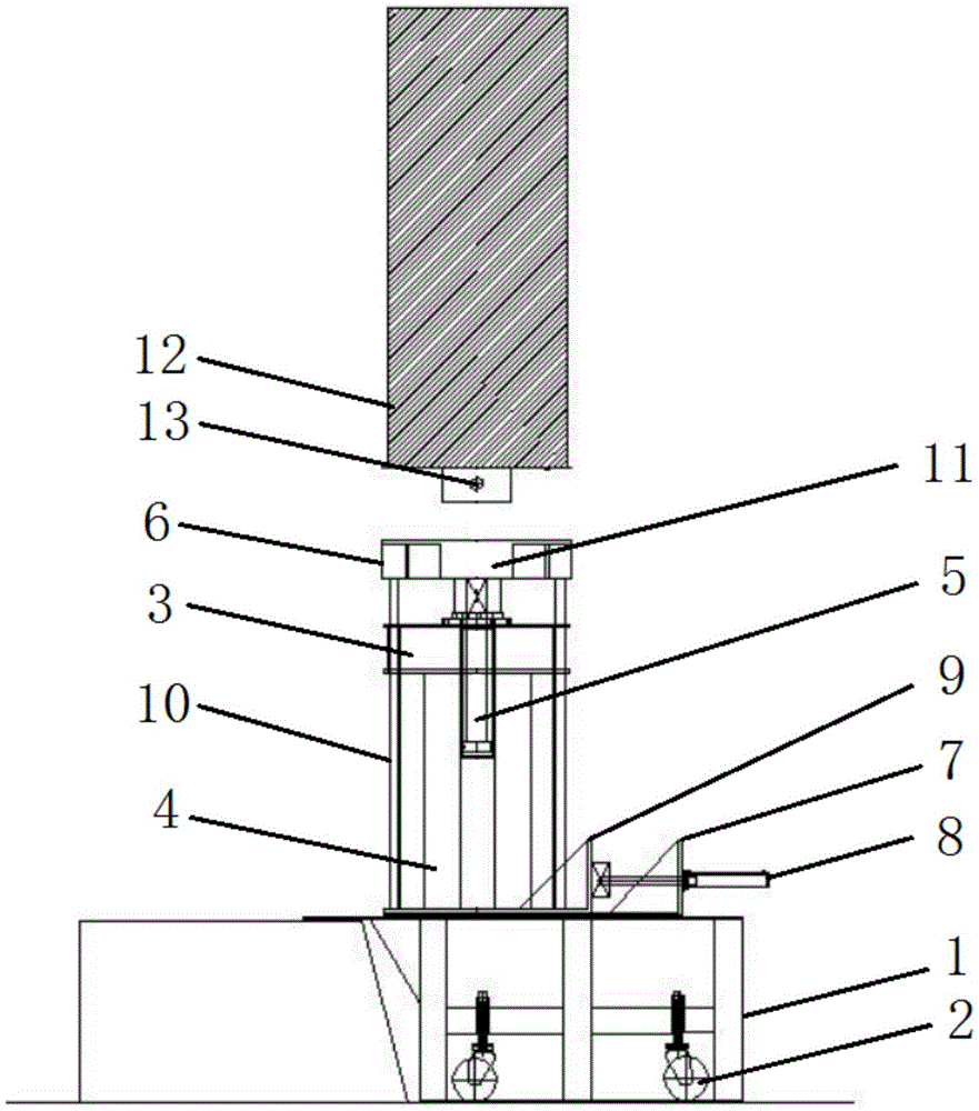
Referring to fig. 1-3, a lifting trolley capable of horizontally carrying heavy objects comprises an underframe 1, wherein at least two traveling mechanisms 2 are arranged on the underframe 1, and each traveling mechanism 2 is connected with the underframe 1; a support frame 3 is arranged above the bottom frame 1, the support frame 3 is connected with the bottom frame 1 through an upright post 4, a hydraulic cylinder I5 is vertically arranged inside the support frame 3, and the hydraulic cylinder I5 is fixedly connected with the support frame 3; a connecting frame 6 is arranged above the support frame 3, an output shaft of the first hydraulic cylinder 5 is fixedly connected with the connecting frame 6, and the connecting frame 6 is connected with the support frame 3 in a sliding mode. The connecting frame 6 has a placement groove 11 in its interior.
The top of the chassis 1 is also provided with a fixing plate 7; the fixing plate 7 is L-shaped; and a second hydraulic cylinder 8 is arranged on the side wall of the fixed plate 7. The fixed plate 7 is a stainless steel plate; the slide plate 9 is a steel plate. A sliding plate 9 is arranged on the fixed plate 7; and the output shaft of the second hydraulic cylinder 8 is fixedly connected with the sliding plate 9. The bottoms of the two ends of the connecting frame 6 are provided with guide posts 10; each guide post 10 extends through the support frame 3 and extends downwardly.
In this embodiment, through setting up chassis 1, still be provided with two hydraulic pumps and an oil tank on this chassis 1, the oil inlet of two hydraulic pumps all is linked together with the oil tank, the oil-out of two hydraulic pumps is linked together with pneumatic cylinder 5 and pneumatic cylinder two 8 respectively through two oil pipes, the solenoid valve has still been installed on every oil pipe, this hydraulic pump design pressure can be 31.5Mpa, pneumatic cylinder lifting speed is about 50mm in one minute, this device adopts two pump bodies, two way solenoid valves, and through installing the remote control button handle on an oil tank, misoperation and mutual interference risk can be avoided.
By arranging the first hydraulic cylinder 5, when the first hydraulic cylinder 5 works, an output shaft of the first hydraulic cylinder 5 extends out, so that the connecting frame 6 is driven to move in the vertical direction until the connecting frame is contacted with the heavy object 12. By providing the link frame 6, since the link frame 6 has the placing groove 11 and the bottom of the weight 12 has the mounting member, when the mounting member is inserted into the placing groove 11, the user can mount the weight 12 on the link frame 6 by the bolt 13, thereby preventing the weight 12 from falling off when moving.
By arranging the fixed plate 7 and the sliding plate 9, when the second hydraulic cylinder 8 works, the output shaft of the second hydraulic cylinder 8 extends out, so that the sliding plate 9 is driven to slide on the fixed plate 7; because the fixed plate 7 is a stainless steel plate and the sliding plate 9 is a steel plate, the plane friction between the steel plate and the stainless steel plate during the transverse displacement is reduced, and the resistance is reduced. By arranging the guide post 10, the guide post 10 can provide a guide for the movement of the connecting frame 6 in the vertical direction, and the connecting frame 6 is prevented from shifting in the horizontal direction.
Referring to fig. 4, the traveling mechanism 2 includes a cylinder 21; the cylinder 21 is positioned on the side wall of the bottom frame 1 and is fixedly connected with the bottom frame 1; an expansion rod 22 is vertically arranged in the cylinder 21; one end of the telescopic rod 22 is fixedly connected with the barrel 21, and the other end of the telescopic rod 22 is provided with a walking wheel 23. The outer wall of the telescopic rod 22 is sleeved with a spring 24; one end of the spring 24 is fixedly connected with the cylinder 21, and the other end of the spring 24 is connected with the travelling wheel 23.
In the present embodiment, by providing the cylinder 21, the arrangement of the cylinder 21 provides support for the telescopic rod 22 and the spring 24; through setting up walking wheel 23, this walking wheel 23 set up the staff of being convenient for and remove this device. By arranging the telescopic rod 22 and the spring 24, when the load of the device exceeds the supporting force of the spring 24, the walking wheel 23 retracts, and the chassis 1 is contacted with the ground.
In conclusion, through setting up pneumatic cylinder 5, when the user opened pneumatic cylinder 5, the output shaft of pneumatic cylinder 5 drove link 6 and moves on vertical direction, until make link 6 and heavy object 12 contact, install heavy object 12 on link 6 through bolt 13 this moment, drive heavy object 12 through pneumatic cylinder 5 at last and descend, until make link 6 and support frame 3 contact, make pneumatic cylinder 5 and stand 4 prop heavy object 12 simultaneously, this device avoids the manual work to hold heavy object 12 and transports, when using manpower sparingly, efficiency is improved. Through setting up guide pillar 10, when the output shaft of pneumatic cylinder 5 drove link 6 and moves in the vertical direction, link 6 passes through guide pillar 10 and slides in the inside of support frame 3 to for link 6's removal provides the direction, when avoiding link 6 to move in the vertical direction, take place the skew in the horizontal direction.
The above description is only for the purpose of illustrating the preferred embodiments of the present invention and is not to be construed as limiting the utility model, and any modifications, equivalents and improvements made within the spirit and principle of the present invention are intended to be included within the scope of the present invention.