Lifting platform based on trolley for elevator load test
Technical Field
The utility model relates to the technical field of elevator load test auxiliary equipment, in particular to a lifting platform based on a trolley for an elevator load test.
Background
The elevator needs the periodic load performance that carries on in daily use to detect, and traditional inspection mode detects through the dead load experiment, carries the load weight to elevator car promptly, and inspection process is more troublesome, and especially the transport of load counter weight is very hard low efficiency.
The existing device has slow speed, low precision and great inconvenience in the process of carrying heavy objects. It is therefore desirable to design a lifting platform that provides the device with the ability to lift heavy objects while avoiding injury to the operator.
Disclosure of Invention
The utility model aims to provide a lifting platform based on a trolley for an elevator load test, so as to solve the problems in the background technology.
The technical scheme of the utility model is as follows:
a lifting platform based on a trolley for an elevator load test comprises a chassis, a carrying platform, a central driving mechanism and a closed-loop lifting unit, wherein the closed-loop lifting unit comprises a lifting trolley, a lifting center pillar and a pair of scissor arms symmetrically arranged between the chassis and the carrying platform, each scissor arm comprises a chassis scissor arm and a carrying scissor arm, the chassis scissor arms and the carrying scissor arms are connected in a rotating fit mode through a center pin shaft, the lower ends of the chassis scissor arms are connected with a hinged base fixed on the chassis in a rotating fit mode, the upper ends of the chassis scissor arms are in sliding contact with the lower surface of the carrying platform, the upper ends of the carrying scissor arms are connected with the hinged base fixed on the lower surface of the carrying platform in a rotating fit mode, and the lower ends of the carrying scissor arms are in sliding contact with the upper surface of the chassis;
a lifting center pillar is fixedly connected between the left chassis scissor arm and the right chassis scissor arm;
the lifting trolley is in front-back sliding fit with the upper surface of the chassis, a pair of vertical seat plates extend from the lifting trolley, vertical guide grooves are formed in the vertical seat plates, and the vertical guide grooves are sleeved on the lifting center pillars;
the output end of the central driving mechanism is in driving connection with the lifting trolley.
Preferably, the central driving mechanism comprises a guide rod sliding block mechanism and a motor fixedly mounted on the chassis, the guide rod sliding block mechanism comprises a first guide rod, a second guide rod and a sliding block which are fixedly connected with the output end of the motor, the end part of the first guide rod is connected with the end part of the second guide rod in a rotating fit manner, the other end of the second guide rod is connected with the sliding block in a rotating fit manner, and the sliding block is fixedly connected with the rear end of the lifting trolley.
Preferably, a pair of chassis guide rails is fixedly installed on the upper surface of the chassis, a bottom roller is rotatably installed at the lower end of the carrying scissor arm, and the carrying scissor arm is in sliding fit with the chassis guide rails through the bottom roller.
Preferably, a pair of top guide rails is fixedly mounted on the lower surface of the carrying platform, a top roller is rotatably mounted at the upper end of the chassis scissor arm, and the chassis scissor arm is in sliding fit with the top guide rails through the top roller.
Preferably, a bottom limiting baffle is further fixedly mounted at the inner side end of the upper surface of the chassis corresponding to the chassis guide rail.
Preferably, the inner side end of the lower surface of the carrying platform, which corresponds to the top guide rail, is also fixedly provided with a top limit baffle.
Preferably, a trolley guide rail is fixedly mounted on the upper surface of the chassis, the lifting trolley is in sliding fit with the trolley guide rail through wheels at the bottom, and a trolley limiting baffle is fixedly mounted on the upper surface of the chassis corresponding to the inner side end of the trolley guide rail.
Preferably, still fixed mounting has middle column jacket in the middle of the lift center pillar, and two vertical bedplate are located the left and right sides of middle column jacket respectively.
The utility model has the advantages that: the elevator load test device is reasonable in structural design and flexible in movement, the guide rod and slide block mechanism is adopted as the control mechanism, stable lifting of the carrying platform can be achieved, operation of lifting heavy objects can be completed, and the elevator load test detection efficiency can be improved.
Drawings
The utility model is further described with reference to the following figures and examples:
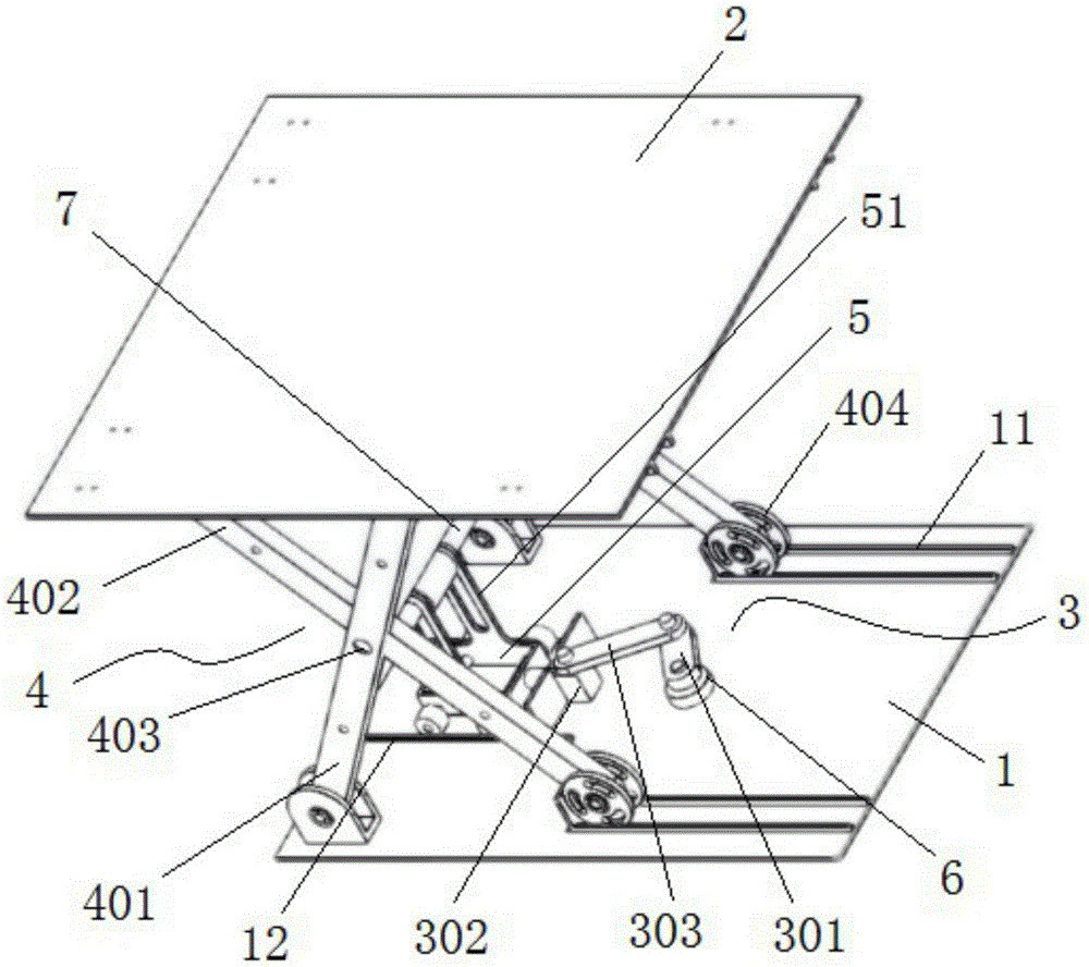
FIG. 1 is a schematic perspective view of the present invention;
FIG. 2 is a right side view of the present invention;
FIG. 3 is a schematic perspective view of a base plate according to the present invention;
FIG. 4 is a schematic perspective view of the carrying platform of the present invention;
FIG. 5 is a schematic perspective view of a central driving mechanism according to the present invention;
fig. 6 is a schematic perspective view of the scissor arm according to the present invention.
Wherein: 1-chassis, 11-chassis rail, 12-trolley rail, 13-bottom limit stop, 14-trolley limit stop, 2-carrying platform, 21-top rail, 22-top limit stop, 3-guide bar slider mechanism, 301-first guide bar, 302-slider, 303-center pin, 4-scissor arm, 401-chassis scissor arm, 402-carrying scissor arm, 403-center pin, 404-bottom roller, 405-top roller, 5-lifting trolley, 51-vertical seat plate, 52-vertical guide slot, 6-motor, 7-lifting center post, 71-center post sleeve.
Detailed Description
Example (b): referring to fig. 1-6, a lifting platform based on a trolley for elevator load test comprises a chassis 1 and a carrying platform 2, and further comprises a central driving mechanism and a closed loop lifting unit, the closed loop lifting unit comprises a lifting trolley 5, a lifting center post 7 and a pair of scissor arms 4 which are symmetrically arranged between the chassis 1 and the carrying platform 2, the scissor arm 4 comprises a chassis scissor arm 401 and a carrying scissor arm 402, the chassis scissor arm 401 and the carrying scissor arm 402 are connected in a rotating fit manner through a central pin 403, the lower end of the chassis scissor arm 401 is connected in a rotating fit manner with a hinge seat fixed on the chassis 1, the upper end of the chassis scissor arm 401 is in sliding contact with the lower surface of the carrying platform 2, the upper end of the carrying scissor arm 402 is connected with a hinge seat fixed on the lower surface of the carrying platform 2 in a rotating fit manner, and the lower end of the carrying scissor arm 402 is in sliding contact with the upper surface of the chassis 1;
a lifting center column 7 is fixedly connected between the left chassis scissor arm 401 and the right chassis scissor arm 401;
the lifting trolley 5 is in front-back sliding fit with the upper surface of the chassis 1, a pair of vertical seat plates 51 extend from the lifting trolley 5, vertical guide grooves 52 are formed in the vertical seat plates 51, and the vertical guide grooves 52 are sleeved on the lifting center pillars 7;
the output end of the central driving mechanism is in driving connection with the lifting trolley 5.
The central driving mechanism comprises a guide rod sliding block mechanism 3 and a motor 6 fixedly mounted on the chassis 1, the guide rod sliding block mechanism 3 comprises a first guide rod 301, a second guide rod 303 and a sliding block 302 which are fixedly connected with the output end of the motor 6, the end part of the first guide rod 301 is connected with the end part of the second guide rod 303 in a rotating fit mode, the other end of the second guide rod 303 is connected with the sliding block 302 in a rotating fit mode, and the sliding block 302 is fixedly connected with the rear end of the lifting trolley 5.
The working principle of the embodiment is as follows: drive first guide arm 301 and the motion of second guide arm 303 through motor 6, second guide arm 303 promotes lift dolly 5 forward motion, lift dolly 5 of forward motion promotes when going up and down center pillar 7 forward motion and upward movement through vertical guide slot 52 in the vertical bedplate 51, lift center pillar 7 drives chassis scissor arm 401 around the articulated seat swing on the chassis 1, chassis scissor arm 401's upper end promotes to carry on platform 2 and rises, deuterogamy carries on scissor arm 402, can realize carrying on platform 2's steady rising.
A pair of chassis guide rails 11 is fixedly installed on the upper surface of the chassis 1, a bottom roller 404 is rotatably installed at the lower end of the carrying scissor arm 402, and the carrying scissor arm 402 is slidably fitted on the chassis guide rails 11 through the bottom roller 404. And a bottom limiting baffle 13 is fixedly arranged at the inner side end of the chassis 1, which corresponds to the chassis guide rail 11.
A pair of top guide rails 21 is fixedly mounted on the lower surface of the carrying platform 2, a top roller 405 is rotatably mounted at the upper end of the chassis scissor arm 401, and the chassis scissor arm 401 is in sliding fit on the top guide rails 21 through the top roller 405. And a top limit baffle 22 is fixedly arranged at the inner side end of the lower surface of the carrying platform 2 corresponding to the top guide rail 21.
Through the arrangement of the chassis guide rail 11 and the top guide rail 21, the stability of the carrying platform 2 in the lifting process is effectively ensured. The arrangement of the bottom limit baffle 13 and the top limit baffle 22 limits the lifting height, and avoids the mechanism from running excessively.
The upper surface of the chassis 1 is also fixedly provided with a trolley guide rail 12, the lifting trolley 5 is in sliding fit on the trolley guide rail 12 through a bottom wheel, and the upper surface of the chassis 1 is fixedly provided with a trolley limit baffle 14 corresponding to the inner side end of the trolley guide rail 12.
The middle of the lifting center post 7 is also fixedly provided with a middle post sleeve 71, and the two vertical seat plates 51 are respectively positioned at the left side and the right side of the middle post sleeve 71. The middle column sleeve 71 can limit the positions of the two vertical seat plates 51, and is matched with the trolley guide rail 12 to ensure that the lifting trolley 5 always moves along the front and rear directions.
It should be understood that the above-mentioned embodiments are only illustrative of the technical concepts and features of the present invention, and are intended to enable those skilled in the art to understand the contents of the present invention and implement the present invention, and not to limit the scope of the present invention. All modifications made according to the spirit of the main technical scheme of the utility model are covered in the protection scope of the utility model.