Non-woven fabrics garbage collection device
Technical Field
The utility model relates to the technical field of non-woven fabric waste collecting devices, in particular to a non-woven fabric waste collecting device.
Background
With the rapid development of social economy, the non-woven fabric is a new-generation environment-friendly material, has the characteristics of moisture resistance, air permeability, flexibility, light weight, no combustion supporting, easy decomposition, no toxicity or irritation, rich color, low price, recycling and the like, is one of important components of the existing facial mask, and the non-woven fabric facial mask is also the mainstream of the existing facial mask. In the non-woven fabric production enterprises, non-woven fabric leftovers or waste materials are recycled.
However, the existing non-woven fabric waste collecting device has relatively less waste collection, and the subsequent working efficiency is increased; therefore, the existing requirements are not met, and a non-woven fabric waste collecting device is provided for the non-woven fabric waste collecting device.
SUMMERY OF THE UTILITY MODEL
The utility model aims to provide a non-woven fabric waste collecting device, which aims to solve the problems that the conventional non-woven fabric waste collecting device provided by the background technology is relatively less in waste collection, the subsequent working efficiency is increased and the like.
In order to achieve the purpose, the utility model provides the following technical scheme: a non-woven fabric waste collecting device comprises a collecting device body, wherein a stepping motor is arranged above the collecting device body, an electric push rod is arranged between the stepping motor and the collecting device body and is in through connection with the collecting device body, a connecting seat positioned in the collecting device body is arranged below the electric push rod, six clamping grooves are symmetrically formed in the upper end face and the lower end face of the inner part of the connecting seat, a first connecting rod is arranged on one side of the connecting seat, a slot is formed in one side of the first connecting rod, a second connecting rod is arranged on the other side of the connecting seat, an inserting block is fixedly arranged on one side of the second connecting rod and is inserted into the slot, three spring grooves are symmetrically formed in the upper end face and the lower end face of the first connecting rod and the second connecting rod, a spring B is arranged in each spring groove, and a supporting rod is arranged at one end of the spring B, the waste collecting device is characterized in that a clamping block is fixedly arranged at one end of the supporting rod, the clamping block is clamped into the inner side of the clamping groove, weighing heads are fixedly arranged below the first connecting rod and the second connecting rod, a waste collecting box is arranged below the collecting device body, a guide rod is connected in the middle of the waste collecting box in a penetrating mode, and a guide sleeve located below the waste collecting box is sleeved outside the guide rod.
Preferably, the both sides of guide bar all are equipped with the diaphragm, two the below of diaphragm all is equipped with six spring A, can cushion along with spring A's compression when the garbage collection box contacts the diaphragm, protection garbage collection box.
Preferably, the base is arranged below the collecting device body, and supporting legs are fixedly arranged on four end legs below the base to play a role in supporting stably.
Preferably, a limiting plate is arranged above the guide rod and plays a limiting role.
Preferably, the surface below the ballast weight head is provided with a rubber cushion, and the rubber cushion can cushion and protect the contacted object to prevent damage.
Preferably, the front end face of the collecting device body is provided with a stop door, and the surface of the stop door is symmetrically provided with handles, so that the handles can be pulled conveniently to open the stop door, and the waste materials in the collecting device can be taken out.
Preferably, four angles of the clamping block are oblique angles, and the angles below two sides of the clamping groove are oblique angles, so that the first connecting rod and the second connecting rod can be pulled and installed conveniently.
Compared with the prior art, the utility model has the beneficial effects that:
1. the utility model can press the waste material in the collecting device body by gravity through the weight pressing head, can save more space for collecting the waste material, reduces the arrangement of the waste material in the collecting device body, accelerates the working efficiency, the electric push rod connected with the stepping motor can perform telescopic motion through the operation of the stepping motor, and the two sides of the electric push rod move up and down through the weight pressing head connected with the first connecting rod and the second connecting rod, when the waste material is placed in the waste material collecting box, the waste material is pressed by the pressure of the pressure head, and when the waste material is pressed, the scrap collecting box moves downward due to gravity, and the guide sleeve fixedly provided under the scrap collecting box performs a displacement motion outside the guide bar, by means of centralized pressing of the waste materials, the internal space can be saved, and the waste materials can be collected more;
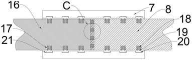
2. the utility model can quickly replace the weight pressing head by inserting the first connecting rod and the second connecting rod into the connecting seat, the insert block arranged at one side of the second connecting rod is inserted into the slot arranged at one side of the first connecting rod, a plurality of clamping blocks are arranged at the upper and lower ends of the first connecting rod and the second connecting rod, because the four corners of the fixture block are the oblique corner edges, the fixture block can be compressed when being inserted into the connecting seat, so that the fixture block is pressed, the supporting rod connected with one end is also pressed, so that the spring B at one end is also compressed, when the spring B touches the clamping grooves at the upper end and the lower end in the connecting seat, the spring B is loosened to pop the clamping block out and clamp the clamping block into the clamping groove to fix the clamping block, when the clamping block is disassembled, the first connecting rod and the second connecting rod only need to be pulled outwards, the inserting block is separated from the slot, and the clamping block can be separated from the clamping groove when the clamping groove is pulled outwards because the clamping groove is also an oblique angle edge.
Drawings
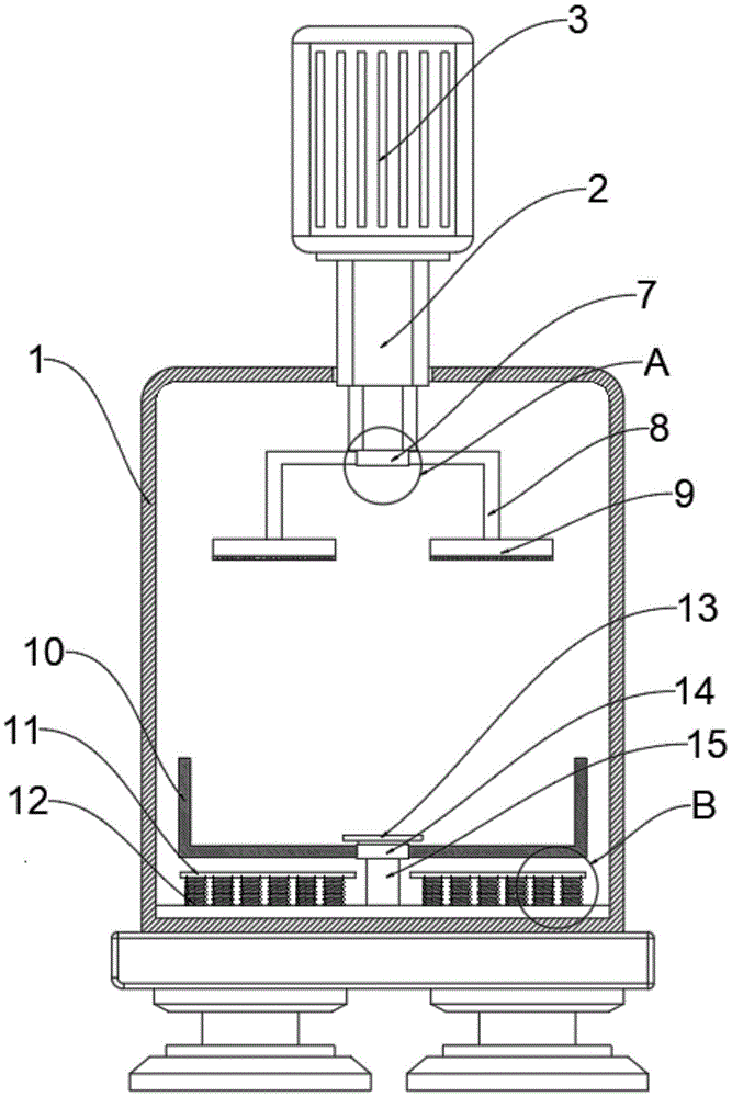
FIG. 1 is a schematic structural view of the present invention as a whole;
FIG. 2 is a schematic view of the internal structure of the whole body of the present invention;
FIG. 3 is a schematic view of the insertion structure at A of the present invention;
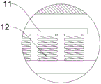
FIG. 4 is an enlarged view of a portion of the structure of the present invention at B;
fig. 5 is an enlarged view of a part of the plugging structure C according to the present invention.
In the figure: 1. a collection device body; 2. an electric push rod; 3. a stepping motor; 4. a shutter; 5. a base; 6. supporting legs; 7. a connecting seat; 8. a first connecting rod; 9. pressing a weight head; 10. a waste collection tank; 11. a transverse plate; 12. a spring A; 13. a limiting plate; 14. a guide sleeve; 15. a guide bar; 16. a second connecting rod; 17. a spring slot; 18. a spring B; 19. a support bar; 20. a clamping block; 21. a card slot; 22. inserting a block; 23. and (4) a slot.
Detailed Description
The technical solutions in the embodiments of the present invention will be clearly and completely described below with reference to the drawings in the embodiments of the present invention, and it is obvious that the described embodiments are only a part of the embodiments of the present invention, and not all of the embodiments.
The electric push rod 2 (model number XTL50) and the stepping motor 3 (model number YS7134) mentioned in the utility model can be obtained from market purchase or private customization.
Referring to fig. 1 to 5, an embodiment of the present invention includes: a non-woven fabric waste collecting device comprises a collecting device body 1, a stepping motor 3 is arranged above the collecting device body 1, an electric push rod 2 is arranged between the stepping motor 3 and the collecting device body 1, the electric push rod 2 is connected with the collecting device body 1 in a penetrating manner, a connecting seat 7 positioned in the collecting device body 1 is arranged below the electric push rod 2, six clamping grooves 21 are symmetrically arranged on the upper end surface and the lower end surface in the connecting seat 7, a first connecting rod 8 is arranged on one side of the connecting seat 7, a slot 23 is arranged on one side of the first connecting rod 8, a second connecting rod 16 is arranged on the other side of the connecting seat 7, an inserting block 22 is fixedly arranged on one side of the second connecting rod 16, the inserting block 22 is inserted into the slot 23, three spring grooves 17 are symmetrically arranged in the upper end surface and the lower end surface of the first connecting rod 8 and the second connecting rod 16, a spring B18 is arranged in each spring groove 17, a supporting rod 19 is arranged at one end of a spring B18, a clamping block 20 is fixedly arranged at one end of the supporting rod 19, the clamping block 20 is clamped into the inner side of the clamping groove 21, the weighting heads 9 are fixedly arranged below the first connecting rod 8 and the second connecting rod 16, the waste collection box 10 is arranged below the collecting device body 1, the guide rod 15 is connected in the middle of the waste collection box 10 in a penetrating mode, and the guide sleeve 14 located below the waste collection box 10 is sleeved outside the guide rod 15.
Further, both sides of the guide rod 15 are provided with transverse plates 11, and six springs A12 are arranged below the two transverse plates 11.
Through adopting above-mentioned technical scheme, can cushion along with the compression of spring A12 when garbage collection box 10 contacts diaphragm 11, protect garbage collection box 10.
Further, a base 5 is arranged below the collecting device body 1, and supporting legs 6 are fixedly arranged on four end legs below the base 5.
Through adopting above-mentioned technical scheme, play the firm effect of support.
Further, a stopper plate 13 is provided above the guide rod 15.
Through adopting above-mentioned technical scheme, play spacing effect.
Further, a rubber cushion is arranged on the surface below the weight head 9.
Through adopting above-mentioned technical scheme, the rubber cushion can cushion, also can protect the object that contacts simultaneously, prevents to damage.
Further, the front end face of the collecting device body 1 is provided with a stop door 4, and the surface of the stop door 4 is symmetrically provided with handles.
Through adopting above-mentioned technical scheme, be convenient for pull the handle, open shutter 4, take out the waste material of inside.
Further, four corners of the latch 20 are oblique angles, and corners below two sides of the engaging groove 21 are oblique angles.
Through adopting above-mentioned technical scheme, be convenient for pull and install first connecting rod 8 and second connecting rod 16.
The working principle is as follows: when the weight-pressing head 9 capable of being replaced quickly is used, the first connecting rod 8 and the second connecting rod 16 are inserted into the connecting seat 7, the inserting block 22 arranged on one side of the second connecting rod 16 is inserted into the inserting groove 23 arranged on one side of the first connecting rod 8, the upper end and the lower end of the first connecting rod 8 and the second connecting rod 16 are respectively provided with a plurality of clamping blocks 20, as the four corners of each clamping block 20 are oblique edges, the clamping blocks are compressed when the connecting seat 7 is inserted, the clamping blocks 20 are pressed, the supporting rod 19 connected with one end is also pressed, the spring B18 at one end is also compressed, when the clamping grooves 21 positioned at the upper end and the lower end in the connecting seat 7 are contacted, the spring B18 is loosened to eject the clamping blocks 20 into the clamping grooves 21 to fix the clamping blocks, when the weight-pressing head 9 is disassembled, the first connecting rod 8 and the second connecting rod 16 are pulled outwards to ensure that the inserting blocks 22 are separated from the inserting grooves 23, and as the clamping grooves 21 are also oblique edges, therefore, when the waste is pulled outwards, the clamping block 20 can be separated from the clamping groove 21, the waste in the collecting device body 1 can be pressed by gravity through the weight pressing head 9, more space can be saved for collecting the waste, the arrangement of the waste in the waste is reduced, the working efficiency is improved, the electric push rod 2 connected with the step motor 3 is made to move in a telescopic manner through the operation of the step motor 3, the two sides of the electric push rod 2 are made to move up and down through the weight pressing head 9 connected with the first connecting rod 8 and the second connecting rod 16, when the waste is placed in the waste collecting box 10, the waste is pressed by the pressure of the weight pressing head 9, when the waste is pressed, the waste collecting box 10 can move downwards due to the gravity, the guide sleeve 14 fixedly arranged below the waste collecting box 10 can move outside the guide rod 15, then can touch diaphragm 11 when trash collection box 10 pushes down, continue to push down then can make a plurality of springs A12 of diaphragm 11 below compressed, play the effect of buffering, through, to the concentrated pressure of waste material move, can save inside space for the collection of more waste materials.
It will be evident to those skilled in the art that the utility model is not limited to the details of the foregoing illustrative embodiments, and that the present invention may be embodied in other specific forms without departing from the spirit or essential attributes thereof. The present embodiments are therefore to be considered in all respects as illustrative and not restrictive, the scope of the utility model being indicated by the appended claims rather than by the foregoing description, and all changes which come within the meaning and range of equivalency of the claims are therefore intended to be embraced therein. Any reference sign in a claim should not be construed as limiting the claim concerned.