CN216226489U - Shallow drawing jig for irregular busbar bottom shell model - Google Patents
Shallow drawing jig for irregular busbar bottom shell model Download PDFInfo
- Publication number
- CN216226489U CN216226489U CN202122825056.9U CN202122825056U CN216226489U CN 216226489 U CN216226489 U CN 216226489U CN 202122825056 U CN202122825056 U CN 202122825056U CN 216226489 U CN216226489 U CN 216226489U
- Authority
- CN
- China
- Prior art keywords
- irregular
- bottom shell
- rotary rod
- gear
- shallow
- Prior art date
- Legal status (The legal status is an assumption and is not a legal conclusion. Google has not performed a legal analysis and makes no representation as to the accuracy of the status listed.)
- Expired - Fee Related
Links
- 230000001788 irregular Effects 0.000 title claims abstract description 18
- 230000008878 coupling Effects 0.000 claims description 2
- 238000010168 coupling process Methods 0.000 claims description 2
- 238000005859 coupling reaction Methods 0.000 claims description 2
- 230000000149 penetrating effect Effects 0.000 claims description 2
- 238000005516 engineering process Methods 0.000 description 4
- 238000000034 method Methods 0.000 description 4
- 230000009471 action Effects 0.000 description 3
- 238000003754 machining Methods 0.000 description 2
- 238000004519 manufacturing process Methods 0.000 description 2
- 230000008569 process Effects 0.000 description 2
- 230000004075 alteration Effects 0.000 description 1
- 230000009286 beneficial effect Effects 0.000 description 1
- 238000012986 modification Methods 0.000 description 1
- 230000004048 modification Effects 0.000 description 1
- 238000006467 substitution reaction Methods 0.000 description 1
Images



Landscapes
- Moulds For Moulding Plastics Or The Like (AREA)
Abstract
The utility model relates to the technical field of shallow drawing tools and discloses a shallow drawing tool for an irregular busbar bottom shell model, which comprises a lower die and an upper die arranged at the upper end of the lower die, wherein a first rotary groove is formed in one side of the outer surface of the lower die, a rotary rod is connected to the inner cavity of the first rotary groove in a shaft mode, a lug is arranged on one side of the outer surface of the rotary rod, a counterweight disc is arranged on one side of the outer surface of the rotary rod, a gear is arranged at one end of the outer surface of the rotary rod, a rack is arranged on one side of the upper end of the upper die and is meshed with the gear, when the upper die moves upwards, the gear can be driven by the rack arranged on one side of the upper end of the upper die to rotate, the rotary rod can be rotated after the gear rotates, the lug can be rotated after the lug rotates, the lower die can vibrate, and material blanking is facilitated through vibration.
Description
Technical Field
The utility model relates to the technical field of shallow drawing jigs, in particular to a shallow drawing jig of an irregular busbar bottom shell model.
Background
With the continuous development of science and technology, the development of the mold industry is more and more rapid, and at the present stage, the production of each manufacturing industry needs to be carried out by adopting a mold, wherein a deep drawing mold is a mold required by one of the processing technologies, and most of the deep drawing molds adopted in the traditional technology adopt downward stamping to form a concave shape on the surface of a product.
Present shallow deep-drawing tool is when using, thereby the processing of material is accomplished to lower mould and last mould mutual closure, but when processing is accomplished the back and need carry out the unloading, because the easy joint of material is inside the tool, and then inconvenient when the unloading.
The problems described above are addressed. Therefore, a shallow drawing jig of the irregular busbar bottom shell model is provided.
SUMMERY OF THE UTILITY MODEL
The utility model aims to provide a shallow drawing jig for an irregular busbar bottom shell model, when an upper die moves upwards, a rack arranged on one side of the upper end of the upper die can drive a gear to rotate, a rotating rod can rotate after the gear rotates, a lug can rotate after the rotating rod rotates, the lower die can vibrate after the lug rotates, and the material blanking is facilitated through the vibration, so that the problems in the background technology are solved.
In order to achieve the purpose, the utility model provides the following technical scheme: the utility model provides a shallow deep-drawing tool of female drain pan model of irregular row, is provided with the mould including lower mould and lower mould upper end, first swivelling chute has been seted up to lower mould surface one side, and first swivelling chute inner chamber coupling has the rotary rod, and rotary rod surface one side is provided with the lug, and rotary rod surface one side is provided with the weight plate, and rotary rod surface one end is provided with the gear, goes up mould upper end one side and is provided with the rack, and the rack is connected with gear engagement.
Preferably, a first return spring is arranged on one side of the inner cavity wall of the first rotating groove, and a first limiting block is arranged at one end of the first return spring.
Preferably, a first limiting groove is formed in one side of the outer surface of the rotating rod.
Preferably, the first limiting blocks are clamped between the adjacent first limiting grooves.
Preferably, a second rotating groove is formed in one side of the outer surface of the gear in a penetrating mode, a second return spring is arranged in the inner cavity of the second rotating groove, and a second limiting block is arranged at one end of the second return spring.
Preferably, a second limiting groove is formed in one end of the outer surface of the rotating rod.
Preferably, the second limiting groove and the first limiting groove are arranged in the same direction.
Preferably, the upper end of the lower die extends downwards to form a shallow deep-drawing groove.
Compared with the prior art, the utility model has the following beneficial effects:
1. according to the shallow drawing jig for the irregular busbar bottom shell model, when the upper die moves upwards, the rack arranged on one side of the upper end of the upper die can drive the gear to rotate, the rotating rod can rotate after the gear rotates, the lug can rotate after the rotating rod rotates, the lower die can vibrate after the lug rotates, and the material blanking is facilitated through the vibration.
2. According to the shallow drawing jig for the irregular busbar bottom shell model, when the upper die moves downwards, the rack can drive the gear to rotate, the gear can be clamped with the first limiting groove through the first limiting block after rotating, so that the rotating rod is prevented from rotating, the phenomenon of vibration during machining is prevented, when the upper die moves upwards, the second limiting block can drive the second limiting groove, so that the rotating rod rotates, vibration is generated during blanking, and the counter weight disc arranged on one side of the outer surface of the rotating rod can accelerate the rotation of the rotating rod, so that blanking is facilitated.
Drawings
FIG. 1 is a schematic view of the overall structure of the present invention;
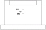
FIG. 2 is a schematic view of the lower mold structure of the present invention;
FIG. 3 is a schematic view of the front view of the internal structure of the lower mold of the present invention;
FIG. 4 is a side view of the internal structure of the lower mold of the present invention;
FIG. 5 is a side view of the internal structure of the gear and the rotating lever of the present invention.
In the figure: 1. a lower die; 11. shallow deep drawing the groove; 12. rotating the rod; 121. a first limit groove; 122. a weight plate; 123. a bump; 124. a second limit groove; 13. a gear; 131. a second rotary tank; 132. a second return spring; 133. a second limiting block; 14. a first rotary tank; 141. a first return spring; 142. a first stopper; 2. an upper die; 21. a rack.
Detailed Description
The technical solutions in the embodiments of the present invention will be clearly and completely described below with reference to the drawings in the embodiments of the present invention, and it is obvious that the described embodiments are only a part of the embodiments of the present invention, and not all of the embodiments. All other embodiments, which can be derived by a person skilled in the art from the embodiments given herein without making any creative effort, shall fall within the protection scope of the present invention.
In order to solve the technical problem of blanking of materials in the shallow deep drawing groove 11, as shown in fig. 1-3, the following preferable technical scheme is provided:
the utility model provides a shallow deep-drawing tool of female drain pan model of irregular row, is provided with mould 2 including 1 lower mould and 1 upper end of lower mould, and first swivelling chute 14 has been seted up to 1 surface one side of lower mould, and 14 inner chamber axle joints of first swivelling chute have rotary rod 12, and 12 surface one sides of rotary rod are provided with lug 123, and 12 surface one side of rotary rod are provided with counterweight plate 122, and 12 surface one end of rotary rod is provided with gear 13, goes up 2 upper end one side of mould and is provided with rack 21, and rack 21 is connected with the meshing of gear 13.
Specifically, when last mould 2 rebound, the rack 21 that last mould 2 upper end one side set up this moment can drive gear 13 and rotate, and gear 13 can make rotary rod 12 rotate after rotatory, and rotary rod 12 can make lug 123 rotate after rotatory, can make lower mould 1 produce the vibration after lug 123 is rotatory, and then make things convenient for the material unloading through the vibration.
In order to solve the technical problem of fast rotation of the rotating rod 12, as shown in fig. 3-5, the following preferred technical solutions are provided:
first reset spring 141 is provided with on one side of the cavity wall in first rotating groove 14, first reset spring 141 one end is provided with first stopper 142, first spacing groove 121 has been seted up on one side of the surface of rotary rod 12, first stopper 142 joint is between adjacent first spacing groove 121, gear 13 surface one side is run through and has been seted up second rotating groove 131, second rotating groove 131 inner chamber is provided with second reset spring 132, second reset spring 132 one end is provided with second stopper 133, second spacing groove 124 has been seted up to rotary rod 12 surface one end, second spacing groove 124 sets up with first spacing groove 121 equidirectional.
Specifically, when the upper die 2 moves downwards, the rack 21 can drive the gear 13 to rotate at the moment, the gear 13 can be connected with the first limit groove 121 through the first limit block 142 after rotating, thereby preventing the rotary rod 12 from rotating, and further preventing the phenomenon of vibration during machining, and when the upper die 2 moves upwards, the second limit block 133 can drive the second limit groove 124 at the moment, thereby rotating the rotary rod 12, thereby generating vibration during blanking, and the weight disc 122 arranged on one side of the outer surface of the rotary rod 12 can accelerate the rotation of the rotary rod 12, so as to facilitate blanking.
It is noted that, herein, relational terms such as first and second, and the like may be used solely to distinguish one entity or action from another entity or action without necessarily requiring or implying any actual such relationship or order between such entities or actions. Also, the terms "comprises," "comprising," or any other variation thereof, are intended to cover a non-exclusive inclusion, such that a process, method, article, or apparatus that comprises a list of elements does not include only those elements but may include other elements not expressly listed or inherent to such process, method, article, or apparatus.
Although embodiments of the present invention have been shown and described, it will be appreciated by those skilled in the art that changes, modifications, substitutions and alterations can be made in these embodiments without departing from the principles and spirit of the utility model, the scope of which is defined in the appended claims and their equivalents.
Claims (8)
1. The utility model provides a shallow deep-drawing tool of female drain pan model of irregular row, is provided with mould (2), its characterized in that including lower mould (1) and lower mould (1) upper end: first swivelling chute (14) have been seted up to lower mould (1) surface one side, and first swivelling chute (14) inner chamber coupling has rotary rod (12), and rotary rod (12) surface one side is provided with lug (123), and rotary rod (12) surface one side is provided with counterweight disc (122), and rotary rod (12) surface one end is provided with gear (13), goes up mould (2) upper end one side and is provided with rack (21), and rack (21) are connected with gear (13) meshing.
2. The shallow drawing jig for the irregular busbar bottom shell model according to claim 1, characterized in that: a first return spring (141) is arranged on one side of the inner cavity wall of the first rotating groove (14), and a first limiting block (142) is arranged at one end of the first return spring (141).
3. The shallow drawing jig for the irregular busbar bottom shell model according to claim 2, characterized in that: a first limiting groove (121) is formed in one side of the outer surface of the rotating rod (12).
4. The shallow drawing jig for the irregular busbar bottom shell model according to claim 3, characterized in that: the first limiting blocks (142) are clamped between the adjacent first limiting grooves (121).
5. The shallow drawing jig for the irregular busbar bottom shell model according to claim 4, characterized in that: a second rotating groove (131) is formed in one side of the outer surface of the gear (13) in a penetrating mode, a second return spring (132) is arranged in the inner cavity of the second rotating groove (131), and a second limiting block (133) is arranged at one end of the second return spring (132).
6. The shallow drawing jig for the irregular busbar bottom shell model according to claim 5, characterized in that: and one end of the outer surface of the rotating rod (12) is provided with a second limiting groove (124).
7. The shallow drawing jig for the irregular busbar bottom shell model according to claim 6, characterized in that: the second limiting groove (124) and the first limiting groove (121) are arranged in the same direction.
8. The shallow drawing jig for the irregular busbar bottom shell model according to claim 7, characterized in that: the upper end of the lower die (1) extends downwards to form a shallow deep drawing groove (11).
Priority Applications (1)
| Application Number | Priority Date | Filing Date | Title |
|---|---|---|---|
| CN202122825056.9U CN216226489U (en) | 2021-11-18 | 2021-11-18 | Shallow drawing jig for irregular busbar bottom shell model |
Applications Claiming Priority (1)
| Application Number | Priority Date | Filing Date | Title |
|---|---|---|---|
| CN202122825056.9U CN216226489U (en) | 2021-11-18 | 2021-11-18 | Shallow drawing jig for irregular busbar bottom shell model |
Publications (1)
| Publication Number | Publication Date |
|---|---|
| CN216226489U true CN216226489U (en) | 2022-04-08 |
Family
ID=80944263
Family Applications (1)
| Application Number | Title | Priority Date | Filing Date |
|---|---|---|---|
| CN202122825056.9U Expired - Fee Related CN216226489U (en) | 2021-11-18 | 2021-11-18 | Shallow drawing jig for irregular busbar bottom shell model |
Country Status (1)
| Country | Link |
|---|---|
| CN (1) | CN216226489U (en) |
-
2021
- 2021-11-18 CN CN202122825056.9U patent/CN216226489U/en not_active Expired - Fee Related
Similar Documents
| Publication | Publication Date | Title |
|---|---|---|
| CN208730218U (en) | A kind of injection mold of rapid shaping | |
| CN102125952B (en) | Liquid-filled deep-drawing forming method for thin-walled sheet metal parts with tapered wall and oblique flange | |
| CN207325905U (en) | A kind of hardware dies demolding structure | |
| CN208514951U (en) | A kind of cylindric spiral gear twisted multi-leg block mold | |
| CN218083269U (en) | Wet-pressing forming equipment for permanent magnetic ferrite product | |
| CN107897240A (en) | A kind of dough kneading equipment of quick Fabrication dough | |
| CN202555616U (en) | Deformation processing device for tubular workpiece | |
| CN111590722B (en) | Concrete block forming device | |
| CN209522759U (en) | Glass moulding press | |
| CN102632098B (en) | Deformation processing device and method of tubular workpiece | |
| CN204712239U (en) | A kind of non-conventional type ceramic product spin forming device | |
| CN211616730U (en) | Herbal pieces-briquetting machine | |
| CN209381464U (en) | A kind of tablet press machine | |
| CN203266866U (en) | Die pressing device of high pressure stone die combined section bar | |
| CN215745776U (en) | Continuous stamping die for forming aluminum shell | |
| CN208483878U (en) | A kind of wafer cutting die facilitating automatic feeding-discharging | |
| CN207900112U (en) | A kind of continuous forging stock molding machine of hardware thin material | |
| CN218946131U (en) | Inverter shell mould | |
| CN216068826U (en) | Leak protection type demolding device | |
| CN221209669U (en) | Stamping forming die | |
| CN222985714U (en) | A pressing die for processing carbide blades that is easy to remove | |
| CN213080034U (en) | A die-casting mold exhaust device | |
| CN223943687U (en) | Orchid-flavored tea processing device | |
| CN212945028U (en) | Fixing device of stamping die part | |
| CN219004502U (en) | Steel roll forming die |
Legal Events
| Date | Code | Title | Description |
|---|---|---|---|
| GR01 | Patent grant | ||
| GR01 | Patent grant | ||
| CF01 | Termination of patent right due to non-payment of annual fee | ||
| CF01 | Termination of patent right due to non-payment of annual fee |
Granted publication date: 20220408 |