CN216221345U - An intelligent sweeping robot integrating sweeping and mopping - Google Patents
An intelligent sweeping robot integrating sweeping and mopping Download PDFInfo
- Publication number
- CN216221345U CN216221345U CN202122278748.6U CN202122278748U CN216221345U CN 216221345 U CN216221345 U CN 216221345U CN 202122278748 U CN202122278748 U CN 202122278748U CN 216221345 U CN216221345 U CN 216221345U
- Authority
- CN
- China
- Prior art keywords
- machine body
- storage box
- water storage
- water
- sweeping robot
- Prior art date
- Legal status (The legal status is an assumption and is not a legal conclusion. Google has not performed a legal analysis and makes no representation as to the accuracy of the status listed.)
- Expired - Fee Related
Links
Images


Landscapes
- Cleaning Implements For Floors, Carpets, Furniture, Walls, And The Like (AREA)
Abstract
Description
技术领域technical field
本实用新型涉及智能扫地机器人技术领域,具体为一种扫地拖地一体化的智能扫地机器人。The utility model relates to the technical field of intelligent sweeping robots, in particular to an intelligent sweeping robot integrating sweeping and mopping.
背景技术Background technique
扫地机器人能够自动完成对地面的清洁工作,现在的扫地机器人往往具备扫拖吸的三种功能,但是经过拖地操作的地面往往很湿滑,需要等待一定时间才能风干,容易造成机器打滑、使用者踩到水渍将地板污染甚至使用者跌倒等问题;并且机器人在地形复杂时会减慢移动速度进行避障,如果水箱仍然保持均匀出水的话,就会导致此处地面湿滑,智能程度较差,降低了整体的实用性。The sweeping robot can automatically complete the cleaning of the ground. The current sweeping robot often has three functions of sweeping, mopping and suction, but the ground that has been mopped is often very slippery and needs to wait for a certain period of time to air dry, which is easy to cause the machine to slip and use. If the user steps on the water stains, the floor will be polluted or even the user will fall; and the robot will slow down its movement speed to avoid obstacles when the terrain is complex. If the water tank still keeps the water evenly, it will cause the ground here to be slippery and more intelligent. poor, reducing the overall usability.
实用新型内容Utility model content
本实用新型的目的在于提供一种扫地拖地一体化的智能扫地机器人,具备可控出水量,有效的避免在拖地时出水量过大导致地面潮湿的优点,解决了现有的拖地操作后的地面较为湿滑,影响整体清洁程度的问题。The purpose of the utility model is to provide an intelligent sweeping robot integrated with sweeping and mopping, which has the advantages of controllable water output, effectively avoiding the advantages of excessive water output during mopping and causing the ground to become wet, and solves the existing mopping operation. The ground behind is slippery, which affects the overall cleanliness.
为实现上述目的,本实用新型提供如下技术方案:一种扫地拖地一体化的智能扫地机器人,包括机器本体,所述机器本体内腔的左侧活动卡设有储水盒,所述储水盒的右侧且位于机器本体的内腔固定安装有隔板,所述储水盒的底部固定安装有下水管,所述下水管的底部固定安装有连接管,所述下水管的内腔固定安装有电控阀,所述连接管的内腔固定安装有溢水棉条,所述机器本体底部左侧的中心处固定安装有弹性板,所述弹性板的底部粘接有清洗布,所述机器本体表面的两侧均固定安装有防撞条,所述防撞条的中心处活动安装有缓冲限位条。In order to achieve the above purpose, the present utility model provides the following technical solutions: an intelligent sweeping robot integrated with sweeping and mopping, including a machine body, and a water storage box is provided on the left movable card of the inner cavity of the machine body, and the water storage box is A partition plate is fixedly installed on the right side of the box and located in the inner cavity of the machine body, the bottom of the water storage box is fixedly installed with a downpipe, the bottom of the downpipe is fixed with a connecting pipe, and the inner cavity of the downpipe is fixed An electric control valve is installed, an overflow tampon is fixedly installed in the inner cavity of the connecting pipe, an elastic plate is fixedly installed at the center of the left side of the bottom of the machine body, and a cleaning cloth is adhered to the bottom of the elastic plate. Anti-collision strips are fixedly installed on both sides of the surface of the machine body, and a buffer limit strip is movably installed at the center of the anti-collision strip.
优选的,所述机器本体顶部的中心处固定安装有红外探测头,所述机器本体顶部的左侧活动卡设有密封块。Preferably, an infrared detection head is fixedly installed at the center of the top of the machine body, and a sealing block is movably clamped on the left side of the top of the machine body.
优选的,所述储水盒顶部的左侧开设有进水口,所述储水盒的左侧固定连接有卡板,所述卡板活动卡设在机器本体左侧的表面。Preferably, a water inlet is provided on the left side of the top of the water storage box, a card plate is fixedly connected to the left side of the water storage box, and the card plate is movably clamped on the surface of the left side of the machine body.
优选的,所述隔板的左侧活动安装有集尘箱,所述集尘箱的底部开设有吸尘口,所述吸尘口的内腔活动卡设有滚筒刷。Preferably, a dust collecting box is movably installed on the left side of the partition, the bottom of the dust collecting box is provided with a dust suction port, and the inner cavity of the dust suction port is movably clamped with a roller brush.
优选的,所述机器本体底部左侧的正面与背面均固定安装有行走轮,所述机器本体底部右侧的中心处固定安装有减震机构,所述减震机构的底部转动安装有转向轮。Preferably, the front and back of the bottom left side of the machine body are fixedly installed with walking wheels, the center of the right side of the bottom of the machine body is fixedly installed with a shock-absorbing mechanism, and the bottom of the shock-absorbing mechanism is rotatably installed with steering wheels .
优选的,所述机器本体的底部且靠近右侧的位置固定安装有安装块,所述安装块的底部活动安装有清洁刷。Preferably, an installation block is fixedly installed at the bottom of the machine body and at a position close to the right side, and a cleaning brush is movably installed at the bottom of the installation block.
与现有技术相比,本实用新型的有益效果如下:Compared with the prior art, the beneficial effects of the present utility model are as follows:
1、本实用新型通过清洁刷可以对地面进行旋转式清扫,随后滚筒刷会进行转动,同时可以通过吸尘口将灰尘颗粒等吸入至集尘箱内,且在清扫后,通过下水管可以将储水盒内的水向下引导,水与溢水棉条相接触后,溢水棉条会进行吸水且会膨胀,随后会通过弹性板缓慢的向下流动,会浸湿清洗布,清洗布会对地面进行拖地,且电控阀会根据机器本体行走的速度进行实时联动,在正常行走的过程中会正常下水,一旦出现行走困难的情况,会减少出水量,如果时间过长会完全进行关闭,停止出水,有效的提高了在拖地后地面干燥的速度,不会使地面太过于湿润,同时解决了现有的拖地操作后的地面较为湿滑,影响整体清洁程度的问题。1. The utility model can perform rotary cleaning on the ground through the cleaning brush, and then the roller brush will rotate, and at the same time, dust particles and the like can be sucked into the dust collecting box through the dust suction port, and after cleaning, through the sewer pipe can be The water in the water storage box is guided downward. After the water comes into contact with the overflow tampon, the overflow tampon will absorb water and expand, and then slowly flow downward through the elastic plate, which will soak the cleaning cloth, which will affect the cleaning cloth. The ground is mopped, and the electric control valve will be linked in real time according to the walking speed of the machine body. During normal walking, the water will be launched normally. Once walking is difficult, the water output will be reduced. If the time is too long, it will be completely closed. , stop the water, effectively improve the drying speed of the ground after mopping, will not make the ground too wet, and solve the problem that the ground after the existing mopping operation is relatively slippery, which affects the overall cleanliness.
2、本实用新型通过卡板的设置,可以直接带动卡板向外抽出,卡板会带动储水盒抽出,对污水进行更换,且清洗布通过魔术贴与弹性板相粘合,便于拆卸后清洗更换,且弹性板的设置可以使清洗布与地面紧密贴合,提高了拖地的清洁程度。2. The utility model can directly drive the card plate to draw out through the setting of the card plate, the card plate will drive the water storage box to draw out, and replace the sewage, and the cleaning cloth is bonded with the elastic plate through the Velcro, which is easy to disassemble. It can be cleaned and replaced, and the setting of the elastic plate can make the cleaning cloth closely fit the ground, which improves the cleanliness of the mopping.
附图说明Description of drawings
图1为本实用新型结构示意图;Fig. 1 is the structural representation of the utility model;
图2为本实用新型结构俯视图;Fig. 2 is the top view of the structure of the utility model;
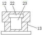
图3为本实用新型下水管与连接管结构剖面图。FIG. 3 is a cross-sectional view of the structure of the sewer pipe and the connecting pipe of the utility model.
图中:1、机器本体;2、红外探测头;3、隔板;4、储水盒;5、密封块;6、进水口;7、卡板;8、防撞条;9、弹性板;10、行走轮;11、清洗布;12、下水管;13、连接管;14、滚筒刷;15、吸尘口;16、清洁刷;17、安装块;18、转向轮;19、减震机构;20、集尘箱;21、缓冲限位条;22、电控阀;23、溢水棉条。In the figure: 1. Machine body; 2. Infrared detector head; 3. Partition plate; 4. Water storage box; 5. Sealing block; 6. Water inlet; 7. Card plate; 8. Anti-collision strip; 9. Elastic plate ; 10, walking wheel; 11, cleaning cloth; 12, drain pipe; 13, connecting pipe; 14, roller brush; 15, suction port; 16, cleaning brush; 17, installation block; 18, steering wheel; 19, reduction Shock mechanism; 20, dust box; 21, buffer limit strip; 22, electric control valve; 23, overflow cotton sliver.
具体实施方式Detailed ways
下面将结合本实用新型实施例中的附图,对本实用新型实施例中的技术方案进行清楚、完整地描述,显然,所描述的实施例仅仅是本实用新型一部分实施例,而不是全部的实施例。基于本实用新型中的实施例,本领域普通技术人员在没有做出创造性劳动前提下所获得的所有其他实施例,都属于本实用新型保护的范围。The technical solutions in the embodiments of the present utility model will be clearly and completely described below with reference to the accompanying drawings in the embodiments of the present utility model. Obviously, the described embodiments are only a part of the embodiments of the present utility model, rather than all the implementations. example. Based on the embodiments of the present invention, all other embodiments obtained by those of ordinary skill in the art without creative work fall within the protection scope of the present invention.
在本申请文件的描述中,需要理解的是,术语“中心”、“上”、“下”、“前”、“后”、“左”、“右”、“竖直”、“水平”、“顶”、“底”、“内”、“外”等指示的方位或位置关系为基于附图所示的方位或位置关系,仅是为了便于描述本专利和简化描述,而不是指示或暗示所指的装置或元件必须具有特定的方位、以特定的方位构造和操作,因此不能理解为对本专利的限制。在本申请文件的描述中,需要说明的是,除非另有明确的规定和限定,术语“安装”、“相连”、“连接”、“设置”应做广义理解,例如,可以是固定相连、设置,也可以是可拆卸连接、设置,或一体地连接、设置。对于本领域的普通技术人员而言,可以根据具体情况理解上述术语在本专利中的具体含义。In the description of this application document, it should be understood that the terms "center", "upper", "lower", "front", "rear", "left", "right", "vertical", "horizontal" , "top", "bottom", "inside", "outside" and other indicated orientations or positional relationships are based on the orientations or positional relationships shown in the accompanying drawings, and are only for the convenience of describing this patent and simplifying the description, rather than indicating or It is implied that the device or element referred to must have a particular orientation, be constructed and operate in a particular orientation, and therefore should not be construed as a limitation of this patent. In the description of this application document, it should be noted that, unless otherwise expressly specified and limited, the terms "installed", "connected", "connected" and "arranged" should be understood in a broad sense, for example, it may be a fixed connection, Setting can also be detachable connection, setting, or integral connection and setting. For those of ordinary skill in the art, the specific meanings of the above terms in this patent can be understood according to specific situations.
请参阅图1-3,一种扫地拖地一体化的智能扫地机器人,包括机器本体1,机器本体1内腔的左侧活动卡设有储水盒4,储水盒4的右侧且位于机器本体1的内腔固定安装有隔板3,储水盒4的底部固定安装有下水管12,下水管12的底部固定安装有连接管13,下水管12的内腔固定安装有电控阀22,连接管13的内腔固定安装有溢水棉条23,机器本体1底部左侧的中心处固定安装有弹性板9,弹性板9的底部粘接有清洗布11,机器本体1表面的两侧均固定安装有防撞条8,防撞条8的中心处活动安装有缓冲限位条21,机器本体1顶部的中心处固定安装有红外探测头2,机器本体1顶部的左侧活动卡设有密封块5,储水盒4顶部的左侧开设有进水口6,储水盒4的左侧固定连接有卡板7,卡板7活动卡设在机器本体1左侧的表面,隔板3的左侧活动安装有集尘箱20,集尘箱20的底部开设有吸尘口15,吸尘口15的内腔活动卡设有滚筒刷14,机器本体1底部左侧的正面与背面均固定安装有行走轮10,机器本体1底部右侧的中心处固定安装有减震机构19,减震机构19的底部转动安装有转向轮18,机器本体1的底部且靠近右侧的位置固定安装有安装块17,安装块17的底部活动安装有清洁刷16,通过卡板7的设置,可以直接带动卡板7向外抽出,卡板7会带动储水盒4抽出,对污水进行更换,且清洗布11通过魔术贴与弹性板9相粘合,便于拆卸后清洗更换,且弹性板9的设置可以使清洗布11与地面紧密贴合,提高了拖地的清洁程度,通过清洁刷16可以对地面进行旋转式清扫,随后滚筒刷14会进行转动,同时可以通过吸尘口15将灰尘颗粒等吸入至集尘箱20内,且在清扫后,通过下水管12可以将储水盒4内的水向下引导,水与溢水棉条23相接触后,溢水棉条23会进行吸水且会膨胀,随后会通过弹性板9缓慢的向下流动,会浸湿清洗布11,清洗布11会对地面进行拖地,且电控阀22会根据机器本体1行走的速度进行实时联动,在正常行走的过程中会正常下水,一旦出现行走困难的情况,会减少出水量,如果时间过长会完全进行关闭,停止出水,有效的提高了在拖地后地面干燥的速度,不会使地面太过于湿润,同时解决了现有的拖地操作后的地面较为湿滑,影响整体清洁程度的问题。Please refer to Fig. 1-3, an intelligent sweeping robot integrated with sweeping and mopping includes a
本实用新型中的所有部件均为通用标准件或本领域技术人员知晓的部件,其结构和原理都为本技术人员均可通过技术手册得知或通过常规实验方法获知,同时本申请文件中使用到的标准零件均可以从市场上购买,本申请文件中各部件根据说明书和附图的记载均可以进行订制,各个零件的具体连接方式均采用现有技术中成熟的螺栓、铆钉、焊接等常规手段,机械、零件和设备均采用现有技术中常规的型号,控制方式是通过控制器来自动控制,控制器的控制电路通过本领域的技术人员简单编程即可实现,属于本领域的公知常识,并且本申请文件主要用来保护机械装置,所以本申请文件不再详细解释控制方式和电路连接,在此不再作出具体叙述。All components in the present invention are general standard components or components known to those skilled in the art, and their structures and principles are known to those skilled in the art through technical manuals or through conventional experimental methods. The standard parts obtained can be purchased from the market. Each part in this application document can be customized according to the description in the description and the attached drawings. The specific connection method of each part adopts the mature bolts, rivets, welding, etc. in the prior art. Conventional means, machinery, parts and equipment all use conventional models in the prior art, the control method is automatically controlled by the controller, and the control circuit of the controller can be realized by simple programming by those skilled in the art, which belongs to the well-known in the art. Common sense, and this application document is mainly used to protect mechanical devices, so this application document will not explain the control method and circuit connection in detail, and will not make a specific description here.
使用时,清洁刷16可以对地面进行旋转式清扫,随后滚筒刷14会进行转动,同时可以通过吸尘口15将灰尘颗粒等吸入至集尘箱20内,且在清扫后,通过下水管12可以将储水盒4内的水向下引导,水与溢水棉条23相接触后,溢水棉条23会进行吸水且会膨胀,随后会通过弹性板9缓慢的向下流动,会浸湿清洗布11,清洗布11会对地面进行拖地,且电控阀22会根据机器本体1行走的速度进行实时联动,在正常行走的过程中会正常下水,一旦出现行走困难的情况,会减少出水量,如果时间过长会完全进行关闭,停止出水。When in use, the cleaning
尽管已经示出和描述了本实用新型的实施例,对于本领域的普通技术人员而言,可以理解在不脱离本实用新型的原理和精神的情况下可以对这些实施例进行多种变化、修改、替换和变型,本实用新型的范围由所附权利要求及其等同物限定。Although the embodiments of the present invention have been shown and described, it will be understood by those skilled in the art that various changes and modifications can be made to these embodiments without departing from the principles and spirit of the present invention , alternatives and modifications, the scope of the present invention is defined by the appended claims and their equivalents.
Claims (6)
Priority Applications (1)
| Application Number | Priority Date | Filing Date | Title |
|---|---|---|---|
| CN202122278748.6U CN216221345U (en) | 2021-09-18 | 2021-09-18 | An intelligent sweeping robot integrating sweeping and mopping |
Applications Claiming Priority (1)
| Application Number | Priority Date | Filing Date | Title |
|---|---|---|---|
| CN202122278748.6U CN216221345U (en) | 2021-09-18 | 2021-09-18 | An intelligent sweeping robot integrating sweeping and mopping |
Publications (1)
| Publication Number | Publication Date |
|---|---|
| CN216221345U true CN216221345U (en) | 2022-04-08 |
Family
ID=80987114
Family Applications (1)
| Application Number | Title | Priority Date | Filing Date |
|---|---|---|---|
| CN202122278748.6U Expired - Fee Related CN216221345U (en) | 2021-09-18 | 2021-09-18 | An intelligent sweeping robot integrating sweeping and mopping |
Country Status (1)
| Country | Link |
|---|---|
| CN (1) | CN216221345U (en) |
Cited By (1)
| Publication number | Priority date | Publication date | Assignee | Title |
|---|---|---|---|---|
| CN116530882A (en) * | 2023-05-04 | 2023-08-04 | 刁伟光 | Cleaning assembly for cleaning robot |
-
2021
- 2021-09-18 CN CN202122278748.6U patent/CN216221345U/en not_active Expired - Fee Related
Cited By (1)
| Publication number | Priority date | Publication date | Assignee | Title |
|---|---|---|---|---|
| CN116530882A (en) * | 2023-05-04 | 2023-08-04 | 刁伟光 | Cleaning assembly for cleaning robot |
Similar Documents
| Publication | Publication Date | Title |
|---|---|---|
| CN107080500B (en) | Intelligent cleaning robot system | |
| CN108670129B (en) | Intelligent floor sweeping robot based on Internet of things and implementation method thereof | |
| CN111419122A (en) | Intelligent automatic floor sweeping and mopping robot | |
| CN202960388U (en) | Automatic cleaning device | |
| CN204654824U (en) | A kind of intelligent floor-sweeping floor-mopping robot | |
| CN209018628U (en) | A kind of use for laboratory floor-mopping robot | |
| CN205144441U (en) | Multifunctional cleaning robot | |
| CN108606736A (en) | A kind of use for laboratory floor-mopping robot | |
| CN107080502B (en) | Intelligent cleaning robot system | |
| CN112120605A (en) | A sweeping and mopping integrated sweeper | |
| CN209750937U (en) | ultrasonic cleaning seat and automatic ground cleaning equipment | |
| US20220386840A1 (en) | Sweeping and mopping integrated household intelligent robot | |
| CN204523690U (en) | Large-sized photovoltaic power station photovoltaic module automatic rinser | |
| CN207755221U (en) | A kind of sweeping robot | |
| CN210902828U (en) | A household sweeping robot | |
| CN104116465B (en) | Intelligent robot cleaner assembly line type floor mopping device and method | |
| CN203000795U (en) | Vacuum sweeper capable of spanning inside corner to work and cleaning vertical plane surfaces and ceiling surfaces | |
| CN207370674U (en) | Intelligent sweeping machine device people | |
| CN109199266A (en) | A kind of intelligent sweeping robot | |
| CN214022182U (en) | Energy-saving external cleaning device for air conditioner | |
| CN211674028U (en) | A sweeping robot with easy handling of dust | |
| CN211883623U (en) | A circulating air outlet device for a sweeping robot | |
| CN210185491U (en) | An adjustable intelligent cleaning machine | |
| CN209984158U (en) | Household cleaning robot | |
| CN206500947U (en) | A kind of terrace cleaning plant with dedusting function |
Legal Events
| Date | Code | Title | Description |
|---|---|---|---|
| GR01 | Patent grant | ||
| GR01 | Patent grant | ||
| TR01 | Transfer of patent right |
Effective date of registration: 20221206 Address after: 710000 Room 403-001, Block F, Youxin Electronic Park, No. 1701, Shanglinyuan 4th Road, Hi tech Zone, Xi'an, Shaanxi Patentee after: Xi'an Shangchen Information Technology Co.,Ltd. Address before: 056002 science and technology innovation office, room 1417, 14 / F, xihuigu building, 50m north of Zhonghua bridge, Zhonghua North Street, Congtai District, Handan City, Hebei Province Patentee before: Zhang Zhenxi |
|
| TR01 | Transfer of patent right | ||
| CF01 | Termination of patent right due to non-payment of annual fee |
Granted publication date: 20220408 |
|
| CF01 | Termination of patent right due to non-payment of annual fee |