Motor rotor maintenance location frock
Technical Field
The utility model relates to the technical field of motor maintenance, in particular to a motor rotor maintenance positioning tool.
Background
The motor usually includes motor casing, motor stator, electric motor rotor, and electric motor rotor usually includes rotor core, rotor winding, axle, commutator again and constitutes, and electric motor rotor is the core component of motor, and when the motor broke down, the normal condition all is that electric motor broke down, consequently need overhaul electric motor. Because there is the difference in the axial length of the electric motor rotor of different models, need adjust electric motor rotor's gesture when overhauing moreover, for example height, inclination etc. electric motor rotor location frock all is the simple centre gripping of electric motor rotor at present, is difficult to adjust the inclination of rotor, and the commonality is lower, is difficult to match the electric motor rotor location of different models.
SUMMERY OF THE UTILITY MODEL
The utility model provides a maintenance positioning tool for a motor rotor, which can adjust the height and the inclination angle of an electronic rotor and has strong universality, in order to solve the problems of maintenance positioning of the motor rotor in the prior art.
In order to achieve the purpose, the utility model adopts the following technical scheme:
a motor rotor maintenance positioning tool comprises a base, wherein vertical plates are arranged at two ends of the base, two parallel sliding rods are arranged between the vertical plates, two sliding seats are arranged between the two sliding rods, the sliding rods penetrate through the sliding seats to be connected with the sliding seats in a sliding mode, a horizontal screw rod parallel to the sliding rods is further arranged between the vertical plates, threads with opposite rotation directions at two ends are arranged on the horizontal screw rod, the two threads are respectively in threaded connection with the two sliding seats in a one-to-one correspondence mode, and a handle is fixed at one end of the horizontal screw rod; the upper end of the sliding seat is provided with a height adjusting mechanism, the upper end of the height adjusting mechanism is provided with a connecting seat, the connecting seat is provided with a hoop component, and the hoop component is rotatably connected with the connecting seat. Drive horizontal screw through the handle and rotate, can drive two sliding seats when horizontal screw rotates and be close to or keep away from in step to adjust the distance between the sliding seat, adjust to suitable distance after, rethread height adjusting mechanism height-adjusting and inclination (difference in height), two staple bolt subassemblies are held tightly, are fixed a position with electric motor rotor's both ends respectively, in order to satisfy detection, maintenance demand. The tool is convenient to use and high in universality.
Preferably, the height adjusting mechanism comprises a bottom plate and a lifting plate parallel to the bottom plate, guide pillars are fixed at two ends of the bottom plate, sliding sleeves in one-to-one corresponding sliding connection with the guide pillars are fixed at two ends of the lifting plate, a vertical screw rod is arranged at the center of the bottom plate and is rotationally connected with the bottom plate, the upper end of the vertical screw rod penetrates through the lifting plate and is in threaded connection with the lifting plate, the bottom plate is fixedly connected with a sliding seat, an avoiding cavity is arranged on the sliding seat, the lower end of the vertical screw rod extends into the avoiding cavity, an adjusting handle is arranged at the lower end of the vertical screw rod, and a limiting convex ring is arranged at the upper end of the vertical screw rod; and the two ends of the connecting seat are fixedly connected with the upper end of the sliding sleeve. The height of the lifting plate can be adjusted by rotating the vertical screw rod, so that the height of the connecting seat is adjusted.
Preferably, the hoop assembly comprises a lower hoop body and an upper hoop body, semicircular grooves are formed in the lower hoop body and the upper hoop body, rotating shafts are arranged at two ends of the lower hoop body, two connecting lugs are arranged on the top surface of the connecting seat, the rotating shafts are rotatably connected with the connecting lugs, and two ends of the upper hoop body are connected with the lower hoop body through bolts. After the shaft of the motor rotor is clamped into the semicircular groove, the upper hoop body and the lower hoop body are connected and tightly hold the motor rotor shaft through bolts.
Preferably, the upper side of the sliding seat is provided with a protection plate, four corners of the lower end of the protection plate are fixedly connected with the base through stand columns, and the protection plate is provided with an avoidance elongated slot for avoiding the guide column and the vertical screw rod. The protection plate plays a role in protection and isolates the parts on the upper side of the protection plate from the parts on the lower side of the protection plate.
Therefore, the motor rotor adjusting device has the advantages of being convenient to use, capable of adjusting the height and the inclination angle of the motor rotor and high in universality.
Drawings
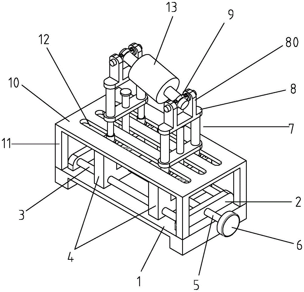
FIG. 1 is a schematic diagram of a structure of the present invention.
Fig. 2 is a front view of fig. 1.
Fig. 3 is a top view of fig. 1.
Fig. 4 is a schematic structural view of fig. 1 with the guard plate removed.
Fig. 5 is a schematic connection diagram of the connecting seat, the height adjusting mechanism and the sliding seat.
In the figure: the device comprises a base 1, a vertical plate 2, a sliding rod 3, a sliding seat 4, an avoiding cavity 40, a horizontal screw rod 5, a handle 6, a height adjusting mechanism 7, a bottom plate 70, a lifting plate 71, a guide pillar 72, a sliding sleeve 73, a vertical screw rod 74, an adjusting handle 75, a limiting convex ring 76, a connecting seat 8, a connecting lug 80, a hoop component 9, a lower hoop body 90, an upper hoop body 91, a semicircular groove 92, a rotating shaft 93, a protection plate 10, a stand column 11, an avoiding long groove 12 and a motor rotor 13.
Detailed Description
The utility model is further described with reference to the accompanying drawings and the detailed description below:
as shown in fig. 1, 2, 3 and 4, the motor rotor maintenance positioning tool comprises a base 1, wherein vertical plates 2 are arranged at two ends of the base 1, two parallel sliding rods 3 are arranged between the vertical plates, two sliding seats 4 are arranged between the two sliding rods, the sliding rods 3 penetrate through the sliding seats to be in sliding connection with the sliding seats, horizontal screw rods 5 parallel to the sliding rods are further arranged between the vertical plates 2, threads with opposite rotation directions at two ends are arranged on the horizontal screw rods, the two sections of threads are in one-to-one corresponding threaded connection with the two sliding seats respectively, and a handle 6 is fixed at one end of each horizontal screw rod 5; the upper end of sliding seat 4 all is equipped with height adjusting mechanism 7, and height adjusting mechanism 7's upper end is equipped with connecting seat 8, is equipped with staple bolt subassembly 9 on the connecting seat, and staple bolt subassembly 9 rotates with the connecting seat to be connected.
As shown in fig. 4, the height adjusting mechanism 7 includes a bottom plate 70 and a lifting plate 71 parallel to the bottom plate, wherein guide posts 72 are fixed at two ends of the bottom plate, sliding sleeves 73 slidably connected with the guide posts in a one-to-one correspondence are fixed at two ends of the lifting plate 71, a vertical screw 74 is arranged at the center of the bottom plate 70 and rotatably connected with the bottom plate, the upper end of the vertical screw 74 passes through the lifting plate and is in threaded connection with the lifting plate, the bottom plate 70 is fixedly connected with the sliding seat 4, an avoiding cavity 40 is arranged on the sliding seat 4, the lower end of the vertical screw extends into the avoiding cavity, an adjusting handle 75 is arranged at the lower end of the vertical screw 74, and a limiting convex ring 76 is arranged at the upper end of the vertical screw 74; the both ends of connecting seat 8 and the upper end fixed connection of sliding sleeve 73, staple bolt subassembly 9 include staple bolt body 90 down, go up staple bolt body 91, all be equipped with half slot 92 on staple bolt body, the last staple bolt body down, the both ends of staple bolt body are equipped with pivot 93 down, and the top surface of connecting seat 8 is equipped with two engaging lugs 80, and pivot 93 rotates with engaging lug 80 to be connected, goes up the both ends of staple bolt body and passes through bolt and this body coupling of lower staple bolt.
The upper side of sliding seat 4 is equipped with guard plate 10, through stand 11 and base fixed connection on four angles of the lower extreme of guard plate 10, is equipped with the elongated slot 12 of dodging that is used for dodging guide pillar, vertical screw on the guard plate.
The principle of the utility model is as follows with reference to the attached drawings: drive horizontal screw through the handle and rotate, can drive two sliding seats when horizontal screw rotates and be close to or keep away from in step to adjust the distance between the sliding seat, adjust to suitable distance after, rethread height adjusting mechanism height-adjusting and inclination (difference in height), two staple bolt subassemblies are held tightly, are fixed a position with electric motor rotor 13's both ends respectively, in order to satisfy detection, maintenance demand. The tool is convenient to use and high in universality.
The above is only a specific embodiment of the present invention, but the technical features of the present invention are not limited thereto. Any simple changes, equivalent substitutions or modifications made based on the present invention to solve the same technical problems and achieve the same technical effects are within the scope of the present invention.