CN216200208U - Single-support two-stage transmission planetary gear reducer - Google Patents
Single-support two-stage transmission planetary gear reducer Download PDFInfo
- Publication number
- CN216200208U CN216200208U CN202122600014.5U CN202122600014U CN216200208U CN 216200208 U CN216200208 U CN 216200208U CN 202122600014 U CN202122600014 U CN 202122600014U CN 216200208 U CN216200208 U CN 216200208U
- Authority
- CN
- China
- Prior art keywords
- gear
- ball bearing
- planetary gear
- ring
- hole
- Prior art date
- Legal status (The legal status is an assumption and is not a legal conclusion. Google has not performed a legal analysis and makes no representation as to the accuracy of the status listed.)
- Active
Links
Images


Abstract
The utility model provides a single-support two-stage transmission planetary gear reducer, and belongs to the technical field of machinery. The speed reducer solves the technical problems of low transmission precision, poor running stability, high manufacturing cost and the like of the speed reducer. This planetary gear speed reducer includes the ring gear, flange and output casing, wear to be equipped with the output shaft in the output casing, the embedded input shaft that is equipped with of flange, the inner of input shaft has linked firmly one-level sun gear, still be equipped with a plurality of in the ring gear around the one-level planet wheel of one-level sun gear circumference distribution and every one-level planet wheel all with one-level sun gear and ring gear engaged with, still be equipped with the one-level planet carrier in the ring gear, one side of one-level planet carrier has a plurality of kingpin one along its circumference distribution, the one end and the one-level planet carrier of kingpin one link firmly, the middle part of one-level planet wheel is equipped with cage bearing one, the other end of kingpin one inserts in the cage bearing one. The planetary gear speed reducer has low manufacturing cost, can be connected with a servo motor in a high-precision manner, and improves the transmission precision and the running stability.
Description
Technical Field
The utility model belongs to the technical field of machinery, and relates to a planetary gear reducer, in particular to a single-support two-stage transmission planetary gear reducer.
Background
The speed reducer is an independent component consisting of gear transmission, worm transmission and gear-worm transmission which are enclosed in a rigid shell, and is commonly used as a speed reduction transmission device between a prime mover and a working machine; the speed reducer is generally used for low-speed and large-torque transmission equipment, and the purpose of reducing speed is achieved by meshing a motor, an internal combustion engine or other high-speed running power with a large gear on an output shaft through a gear with a small number of teeth on an input shaft of the speed reducer; the speed reducer can be divided into a gear speed reducer, a worm speed reducer and a planetary gear speed reducer according to the transmission type; the planetary gear reducer is widely used due to the advantages of compact structure, small return clearance, higher precision, long service life, large rated output torque and the like.
Chinese patent (publication number: CN 209340430U; publication date: 2019-09-03) discloses an improved planetary gear reducer, which comprises a motor, a reducer front box cover, a reducer box body, a first-stage reduction gear train input shaft, a first-stage reduction gear train cycloid planetary gear, a first-stage reduction gear train pin type W output mechanism, a first-stage reduction gear train output shaft, a second-stage reduction gear train involute central sun gear, a second-stage reduction gear train involute planetary gear, a second-stage reduction gear train involute inner gear, a second-stage reduction gear train planetary gear carrier (namely an output shaft) and a reducer rear box cover, and is characterized in that: the planetary gear reducer is formed by connecting two stages of planetary gear reduction trains in series, the input shaft of the first stage of the planetary gear reduction train and the output shaft of the first stage of the planetary gear reduction train rotate in the same direction in a K-H-V cycloid planetary gear transmission mode, the involute central sun gear of the second stage of the planetary gear reduction train and the planet gear carrier of the second stage of the planetary gear reduction train are output shafts, the second stage of the planetary gear reduction train and the planet gear carrier of the second stage of the planetary gear reduction train are also in a NGW involute planetary gear transmission mode of rotating in the same direction, and the input shaft and the output shaft of the improved planetary gear reducer rotate in the same direction.
The improved planetary gear reducer disclosed in the above patent document has a complicated structure, is troublesome to install, has a high manufacturing cost, has a low transmission precision, and is not stable in operation.
Disclosure of Invention
The utility model provides a single-support two-stage transmission planetary gear reducer aiming at the problems in the prior art, and the technical problems to be solved by the utility model are as follows: how to improve the transmission precision and the running stability of the speed reducer and reduce the manufacturing cost.
The purpose of the utility model can be realized by the following technical scheme:
a single-support secondary-transmission planetary gear reducer comprises a flange and an output shell, wherein a gear ring is arranged between the flange and the output shell, the gear ring and the gear ring are fixedly connected with the output shell, an output shaft penetrates through the output shell, the single-support secondary-transmission planetary gear reducer is characterized in that an input shaft is embedded in the flange and can move in the circumferential direction of the flange, a primary sun gear is fixedly connected to the inner end of the input shaft, the primary sun gear extends into the gear ring, a plurality of primary planet gears distributed circumferentially around the primary sun gear are further arranged in the gear ring, each primary planet gear is meshed with the primary sun gear and the gear ring, a primary planet carrier is further arranged in the gear ring, a plurality of roller pins one-to-one corresponding to the primary planet gears are distributed on one side of the primary planet carrier along the circumferential direction of the primary planet carrier, and one end of each roller pin is fixedly connected with the primary planet carrier, the middle part of the primary planet wheel is provided with a first retainer bearing, and the other end of the first roller pin is inserted into the first retainer bearing; a second-stage sun wheel is fixedly connected to the middle of the other side of the first-stage planet carrier and is positioned in the gear ring, a plurality of second-stage planet wheels distributed around the second-stage sun wheel are further arranged in the gear ring, each second-stage planet wheel is meshed with the second-stage sun wheel and the gear ring, a second retainer bearing is arranged in the middle of each second-stage planet wheel, and a plurality of second roller pins which correspond to the second-stage planet wheels one to one are fixedly arranged at one end of the output shaft in the circumferential direction; the second rolling needles are inserted into corresponding second retainer bearings in the second-stage planet wheels.
The working principle is as follows: the input shaft is connected with an output shaft of the servo motor, the input shaft can drive the first-stage sun gear to drive the first-stage planet gears to rotate in the gear ring, the first-stage planet carrier is driven to rotate, the second-stage planet carrier drives the second-stage sun gear to rotate, the second-stage sun gear drives the second-stage planet gears to rotate in the gear ring, and finally the output shaft rotates circumferentially in the output shell. Compared with the traditional flange and input shaft separated structure, the structure enables the servo motor to be connected with the speed reducer in a high-precision manner, so that the transmission precision and the running stability of the speed reducer are improved; the speed reducer is simple in overall structure and convenient to install, not only is the manufacturing cost reduced, but also the manufacturing period is shortened, the gear ring is fixedly connected with the flange and the output shell, so that the gear ring does not move all the time when the speed reducer operates, and the guarantee is provided for the normal output power of the output shaft.
In the single-support two-stage transmission planetary gear reducer, the input shaft, the output shaft, the primary sun gear and the secondary sun gear are coaxially arranged; the primary planet wheels are at least three and are uniformly distributed around the primary sun wheel at intervals; the secondary planet wheels are at least three and are evenly distributed around the secondary sun wheel at intervals. Preferably, the number of the primary planet wheels and the number of the secondary planet wheels are three.
In the single-support two-stage transmission planetary gear reducer, a mounting hole penetrating from one end to the other end is formed in the middle of the flange, the input shaft is located in the mounting hole, a distance is formed between the outer peripheral surface of the input shaft and the hole wall of the mounting hole, a first deep groove ball bearing is sleeved on the input shaft, the outer ring of the first deep groove ball bearing is connected with the hole wall of the mounting hole, a step surface abutting against the inner ring on one side of the first deep groove ball bearing is formed in the outer peripheral surface of the input shaft, and an annular convex edge abutting against the outer ring on one side of the first deep groove ball bearing is formed in the hole wall of the mounting hole; and the outer peripheral surface of the input shaft is also clamped with an outer clamp spring which is abutted against the inner ring on the other side of the first deep groove ball bearing, and the hole wall of the mounting hole is also clamped with an inner clamp spring which is abutted against the outer ring on the same side of the deep groove ball bearing. The step surface on the input shaft and the annular convex edge on the hole wall of the mounting hole are abutted against the same side of the first deep groove ball bearing to axially limit the side, the outer clamp spring and the inner clamp spring are respectively mounted on the input shaft on the other side of the first deep groove ball bearing and the hole wall of the mounting hole and are also used for axially limiting the first deep groove ball bearing, so that the axial movement of the first deep groove ball bearing is effectively limited, and finally, the input shaft is embedded in the flange and only can circumferentially rotate.
In the single-support two-stage transmission planetary gear reducer, a first mounting groove is arranged in the middle of one end of the output shell, a second mounting groove is arranged in the middle of the bottom of the first mounting groove, a through hole extending to the other end of the output shell is arranged in the middle of the bottom of the second mounting groove, one end of the output shaft is positioned in the first mounting groove, the other end of the output shaft penetrates through the second mounting groove and the through hole and extends out of the output shell, a second deep groove ball bearing and a third deep groove ball bearing which are arranged on the output shaft in a side-by-side spaced manner are arranged in the second mounting groove, the outer ring of the second deep groove ball bearing and the outer ring of the third deep groove ball bearing are both connected with the groove wall of the second mounting groove, an annular partition plate is arranged between the second deep groove ball bearing and the third deep groove ball bearing, one side of the annular partition plate is far away from the second deep groove ball bearing and is abutted against the bottom of the second mounting groove, and an annular boss is arranged on the periphery of one end, positioned in the first mounting groove, of the output shaft, and one side, far away from the annular partition plate, of the third deep groove ball bearing is abutted to the annular boss. The output shell, the output shaft, the deep groove ball bearing II and the deep groove ball bearing three-phase are matched, so that the output shaft can be positioned in the output shell in the radial direction and the axial direction, and the structure greatly reduces the manufacturing cost under the condition that the power output is not influenced.
In the single-support two-stage transmission planetary gear reducer, annular grooves are formed in the outer edges of the end, opposite to the output shell, of the flange, and two sides of the gear ring are embedded in the annular grooves in the flange and the output shell respectively; the last cover of one-level sun gear is equipped with planet wheel gasket one, planet wheel gasket one is located in the ring gear and both sides respectively with the terminal surface of flange and one side looks butt of one-level planet wheel, the cover is equipped with planet wheel gasket two on the second grade sun gear, planet wheel gasket two is located in the ring gear and both sides respectively with the terminal surface of one-level planet carrier and one side looks butt of second grade planet wheel. The other side of the secondary planet wheel is directly abutted against the annular boss to be limited or a planet wheel gasket III is arranged between the annular boss and the annular boss, the axial movement of the primary planet wheel and the axial movement of the secondary planet wheel are limited within a reasonable range through the structure, and the running stability of the planet wheel speed reducer is improved. Output shaft and one-level planet carrier are changed not to the envelope by two envelope planet wheel and carry out the axial spacing effect in order to reach two envelopes through planet wheel gasket one and planet wheel gasket two, and manufacturing cost has been reduceed greatly under the prerequisite of guaranteeing the product quality to this structure, has shortened manufacturing cycle.
In the single-support secondary-transmission planetary gear reducer, the retainer bearing I is embedded in the middle of the primary planet gear and is coaxially arranged with the primary planet gear, the roller pins I are uniformly distributed on the side surface of the primary planet carrier at intervals along the circumferential direction of the primary planet carrier, and a plurality of pin holes I which correspond to the primary planet gear one by one and are used for embedding the other ends of the roller pins I are formed in the side surface of the primary planet carrier; the second retainer bearing is embedded in the middle of the second-stage planet gear and coaxially arranged with the second retainer bearing, the second needle rollers are uniformly distributed on the annular boss at intervals along the circumferential direction of the output shaft, and a plurality of second pin holes which correspond to the second-stage planet gears one to one and are used for embedding the other ends of the second needle rollers are formed in the annular boss. The first-level planet wheel of kingpin connection and first-level planet carrier can give the one-level planet carrier with the power transmission of several one-level planet wheel, and the second-level planet wheel of kingpin connection and annular boss can give the output shaft with the power transmission of several second-level planet wheel, provide the guarantee for this planetary gear speed reducer can normally carry out power transmission.
In foretell single support second grade driven planetary gear reducer, the one end of one-level sun gear insert in the mounting hole of input shaft and both tight fit or link firmly through locking screw, one-level planet carrier middle part has the connecting hole, the one end of second grade sun gear insert in the connecting hole of one-level planet carrier and both tight fit or link firmly through locking screw. The structure ensures that the input shaft stably and reliably transmits the torque to the first-stage sun gear and the first-stage planet carrier stably and reliably transmits the torque to the second-stage sun gear.
In the single-support secondary-transmission planetary gear reducer, a counter bore penetrating through the other side is formed in the position, close to the outer edge, of one side of the flange, a through hole corresponding to the counter bore is formed in the gear ring, a threaded hole corresponding to the through hole is formed in one end of the output shell, an inner hexagonal bolt penetrates through the counter bore, and the end portion of the inner hexagonal bolt penetrates through the through hole and is in threaded connection with the threaded hole. The counter bore arranged on the flange can avoid the mutual interference between the hexagon socket head cap screw and other fixed parts on the flange, and the surface looks smoother and more beautiful.
Compared with the prior art, the utility model has the following advantages:
1. the structure of the flange and the input shaft is optimized, the input shaft can be embedded in the flange and only can rotate in the circumferential direction by utilizing the deep groove ball bearing, and compared with the traditional flange and input shaft separated structure, the structure has higher transmission precision and more stable operation when being connected with a servo motor, thereby improving the transmission precision and the operation stability of the speed reducer.
2. According to the double-enveloping planetary gear transmission mechanism, the output shaft and the primary planetary carrier are changed from double-enveloping planetary gears to non-enveloping planetary gears, and axial limiting is carried out through the planetary gear gasket I and the planetary gear gasket II so as to achieve the double-enveloping effect.
Drawings
Fig. 1 is a sectional view of the present planetary gear reducer.
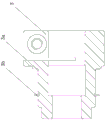
Fig. 2 is a sectional view of a flange in the planetary gear reducer.
Fig. 3 is a sectional view of an input shaft in the planetary gear reducer.
Fig. 4 is a sectional view of the output housing in the present planetary gear reducer.
Fig. 5 is a sectional view of an output shaft of the planetary gear reducer.
In the figure, 1, a flange; 1a, mounting holes; 1a1, annular flange; 1a2, inner snap spring; 1b, counter bores; 2. an output housing; 2a, a first mounting groove; 2b, a second mounting groove; 2c, a through hole; 2d, a threaded hole; 3. an input shaft; 3a, a step surface; 3b, an outer clamp spring; 4. an output shaft; 4a, an annular boss; 4a1 and a second pin hole; 5. a ring gear; 5a, a through hole; 6. a primary sun gear; 7. a primary planet wheel; 8. a primary planet carrier; 8a, a first pin hole; 9. a first roller pin; 10. a first retainer bearing; 11. a secondary sun gear; 12. a secondary planet wheel; 13. A second retainer bearing; 14. a second roller pin; 15. a first deep groove ball bearing; 16. a second deep groove ball bearing; 17. a deep groove ball bearing III; 18. an annular partition plate; 19. an annular groove; 20. a planet wheel gasket I; 21. a planet wheel gasket II; 22. and (4) an inner hexagon bolt.
Detailed Description
The following are specific embodiments of the present invention and are further described with reference to the drawings, but the present invention is not limited to these embodiments.
As shown in fig. 1 to 5, the single-support two-stage transmission planetary gear reducer in this embodiment includes a flange 1 and an output housing 2, a gear ring 5 is disposed between the flange 1 and the output housing 2, and both of them are fixedly connected to the gear ring 5, specifically, a counter bore 1b penetrating through the other side is opened at a position on one side of the flange 1 near an outer edge, a through hole 5a corresponding to the counter bore 1b is opened on the gear ring 5, a threaded hole 2d corresponding to the through hole 5a is opened at one end of the output housing 2, an inner hexagon bolt 22 is inserted into the counter bore 1b, and an end of the inner hexagon bolt 22 passes through the through hole 5a and is screwed into the threaded hole 2 d; an output shaft 4 penetrates through the output shell 2, an input shaft 3 is embedded in the flange 1, the input shaft 3 can move in the flange 1 in the circumferential direction, the inner end of the input shaft 3 is fixedly connected with a primary sun gear 6, the primary sun gear 6 extends into a gear ring 5, a plurality of primary planet gears 7 distributed circumferentially around the primary sun gear 6 are further arranged in the gear ring 5, each primary planet gear 7 is meshed with the primary sun gear 6 and the gear ring 5, a primary planet carrier 8 is further arranged in the gear ring 5, a plurality of roller pins 9 in one-to-one correspondence with the primary planet gears 7 are distributed on one side of the primary planet carrier 8 along the circumferential direction of the one side of the primary planet carrier 8, one end of each roller pin 9 is fixedly connected with the primary planet carrier 8, a retainer bearing I10 is arranged in the middle of the primary planet gear 7, and the other end of each roller pin I9 is inserted into the retainer bearing I10; the middle part of the other side of the primary planet carrier 8 is fixedly connected with a secondary sun gear 11, the secondary sun gear 11 is positioned in the gear ring 5, a plurality of secondary planet gears 12 distributed circumferentially around the secondary sun gear 11 are also arranged in the gear ring 5, each secondary planet gear 12 is meshed with the secondary sun gear 11 and the gear ring 5, a retainer bearing II 13 is arranged in the middle of each secondary planet gear 12, and a plurality of roller pins II 14 in one-to-one correspondence with the secondary planet gears 12 are fixedly arranged at one end of the output shaft 4 in the circumferential direction; the second needle roller 14 is inserted into the second retainer bearing 13 in the corresponding second-stage planet wheel 12. The input shaft 3 is connected with an output shaft 4 of the servo motor, and can drive the first-stage sun gear 6 to drive the plurality of first-stage planet gears 7 to rotate in the gear ring 5, so as to drive the first-stage planet carrier 8 to rotate, the first-stage planet carrier 8 drives the second-stage sun gear 11 to rotate, the second-stage sun gear 11 drives the plurality of second-stage planet gears 12 to rotate in the gear ring 5, and finally the output shaft 4 rotates in the output shell 2 in the circumferential direction. In the embodiment, the input shaft 3 is embedded in the flange 1, and compared with the traditional flange 1 and input shaft 3 separated structure, the structure enables the servo motor to be connected with the speed reducer in a high-precision manner, so that the transmission precision and the running stability of the speed reducer are improved; the speed reducer is simple in overall structure and convenient to install, not only is the manufacturing cost reduced, but also the manufacturing period is shortened, the gear ring 5 is fixedly connected with the flange 1 and the output shell 2, so that the gear ring 5 does not move all the time when the speed reducer operates, and the guarantee is provided for the normal output power of the output shaft 4.
Further, as shown in fig. 1, the input shaft 3, the output shaft 4, the primary sun gear 6 and the secondary sun gear 11 are coaxially arranged; the primary planet wheels 7 are at least three and are uniformly distributed around the primary sun wheel 6 at intervals; the secondary planet wheels 12 are at least three and are evenly distributed around the secondary sun wheel 11 at intervals. Preferably, the number of the primary planet wheels 7 and the number of the secondary planet wheels 12 are three.
As shown in fig. 1 to 3, the middle of the flange 1 is provided with a mounting hole 1a penetrating from one end to the other end, the input shaft 3 is positioned in the mounting hole 1a, a distance is reserved between the outer peripheral surface of the input shaft 3 and the hole wall of the mounting hole 1a, the input shaft 3 is sleeved with a first deep groove ball bearing 15, the outer ring of the first deep groove ball bearing 15 is connected with the hole wall of the mounting hole 1a, the outer peripheral surface of the input shaft 3 is provided with a step surface 3a abutting against the inner ring at one side of the first deep groove ball bearing 15, and the hole wall of the mounting hole 1a is provided with an annular convex edge 1a1 abutting against the outer ring at the side of the first deep groove ball bearing 15; an outer snap spring 3b abutted against the inner ring on the other side of the first deep groove ball bearing 15 is further clamped on the outer peripheral surface of the input shaft 3, and an inner snap spring 1a2 abutted against the outer ring on the same side of the first deep groove ball bearing 15 is further clamped on the hole wall of the mounting hole 1 a. The step surface 3a on the input shaft 3 and the annular convex edge 1a1 on the hole wall of the mounting hole 1a are abutted against the same side of the deep groove ball bearing I15, the side is axially limited, the outer snap spring 3b and the inner snap spring 1a2 are respectively mounted on the input shaft 3 and the hole wall of the mounting hole 1a on the other side of the deep groove ball bearing I15, the deep groove ball bearing I15 is also axially limited, so that the axial movement of the deep groove ball bearing I15 is effectively limited, and finally the input shaft 3 is embedded in the flange 1 and can only circumferentially rotate.
Referring to fig. 4, a first mounting groove 2a is formed in the middle of one end of the output housing 2, a second mounting groove 2b is formed in the middle of the bottom of the first mounting groove 2a, a through hole 2c extending to the other end of the output housing 2 is formed in the middle of the bottom of the second mounting groove 2b, one end of the output shaft 4 is located in the first mounting groove 2a, the other end of the output shaft passes through the second mounting groove 2b and the through hole 2c and extends out of the output housing 2, a second deep groove ball bearing 16 and a third deep groove ball bearing 17 which are sleeved on the output shaft 4 side by side at intervals are arranged in the second mounting groove 2b, an outer ring of the second deep groove ball bearing 16 and an outer ring of the third deep groove ball bearing 17 are both connected with the wall of the second mounting groove 2b, an annular partition plate 18 is arranged between the second deep groove ball bearing 16 and the third groove ball bearing 17, one side of the second deep groove ball bearing 16, which is far away from the annular partition plate 18, is abutted with the bottom of the mounting groove 2b, an annular boss 4a is formed on the outer periphery of one end of the output shaft 4, the side of the deep groove ball bearing III 17 far away from the annular partition plate 18 abuts against the annular boss 4 a. The output housing 2, the output shaft 4, the second deep groove ball bearing 16 and the third deep groove ball bearing 17 are matched to enable the output shaft 4 to be positioned in the output housing 2 in the radial direction and the axial direction, and the structure greatly reduces the manufacturing cost under the condition that power output is not affected.
As shown in fig. 1 and 4, the outer edges of the end of the flange 1 opposite to the output housing 2 are provided with annular grooves 19, and both sides of the ring gear 5 are respectively embedded in the annular grooves 19 on the flange 1 and the output housing 2; the first-stage sun gear 6 is sleeved with a first planet wheel gasket 20, the first planet wheel gasket 20 is located in the gear ring 5, two sides of the first planet wheel gasket 20 are respectively abutted to the end face of the flange 1 and one side face of the first-stage planet wheel 7, the second sun gear 11 is sleeved with a second planet wheel gasket 21, the second planet wheel gasket 21 is located in the gear ring 5, and two sides of the second planet wheel gasket 21 are respectively abutted to the end face of the first-stage planet carrier 8 and one side face of the second planet wheel 12. The other side surface of the secondary planet wheel 12 is directly abutted against the annular boss 4a for limiting or a planet wheel gasket III is arranged between the two, the axial movement of the primary planet wheel 7 and the secondary planet wheel 12 is limited within a reasonable range through the structure, and the running stability of the planetary gear speed reducer is improved. Output shaft 4 and one-level planet carrier 8 are changed not to the envelope by two envelope planet wheels and carry out the effect of axial spacing in order to reach two envelopes through planet wheel gasket one 20 and planet wheel gasket two 21, and this structure has reduceed manufacturing cost greatly under the prerequisite of guaranteeing the product quality, has shortened manufacturing cycle.
As shown in fig. 1, the retainer bearing i 10 is embedded in the middle of the primary planet gear 7 and is coaxially arranged with the primary planet gear 7, the needle rollers i 9 are uniformly distributed on the side surface of the primary planet carrier 8 at intervals along the circumferential direction of the primary planet carrier 8, and a plurality of pin holes i 8a are formed in the side surface of the primary planet carrier 8, are in one-to-one correspondence with the primary planet gear 7 and allow the other end of the needle rollers i 9 to be embedded; the second retainer bearing 13 is embedded in the middle of the second-stage planet wheel 12 and coaxially arranged with the second retainer bearing, the second needle rollers 14 are uniformly distributed on the annular boss 4a at intervals along the circumferential direction of the output shaft 4, and the annular boss 4a is provided with a plurality of second pin holes 4a1 which are in one-to-one correspondence with the second-stage planet wheel 12 and into which the other ends of the second needle rollers 14 are embedded. One-level planet wheel 7 and one-level planet carrier 8 are connected to kingpin 9 can transmit the power transmission of several one-level planet wheel 7 to one-level planet carrier 8, and second 14 kingpins are connected second grade planet wheel 12 and annular boss 4a and can transmit the power transmission of several second grade planet wheel 12 to output shaft 4, provide the guarantee for this planetary gear speed reducer can normally carry out power transmission.
As shown in fig. 1, one end of the first-stage sun gear 6 is inserted into the mounting hole 1a of the input shaft 3 and is tightly fitted or fixedly connected through a locking screw, the middle part of the first-stage planet carrier 8 is provided with a connecting hole, and one end of the second-stage sun gear 11 is inserted into the connecting hole of the first-stage planet carrier 8 and is tightly fitted or fixedly connected through a locking screw. The structure ensures that the input shaft 3 stably and reliably transmits the torque to the first-stage sun gear 6 and the first-stage planet carrier 8 stably and reliably transmits the torque to the second-stage sun gear 11.
The specific embodiments described herein are merely illustrative of the spirit of the utility model. Various modifications or additions may be made to the described embodiments or alternatives may be employed by those skilled in the art without departing from the spirit or ambit of the utility model as defined in the appended claims.
Claims (8)
1. The utility model provides a singly support driven planetary gear speed reducer of second grade, includes flange (1) and output casing (2), flange (1) with be equipped with between output casing (2) ring gear (5) and the two all with ring gear (5) link firmly, wear to be equipped with output shaft (4) in output casing (2), its characterized in that, the embedded input shaft (3) that is equipped with of flange (1) just input shaft (3) can be in the peripheral motion in flange (1), the inner of input shaft (3) has linked firmly one-level sun gear (6) and one-level sun gear (6) stretch into in ring gear (5), still be equipped with a plurality of in ring gear (5) around one-level planet wheel (7) and every of one-level sun gear (6) circumferential distribution one-level planet wheel (7) all with one-level sun gear (6) with ring gear (5) mesh mutually, a primary planet carrier (8) is further arranged in the gear ring (5), a plurality of roller pin I (9) which are in one-to-one correspondence with the primary planet gears (7) are distributed on one side of the primary planet carrier (8) along the circumferential direction of the primary planet carrier, one end of each roller pin I (9) is fixedly connected with the primary planet carrier (8), a retainer bearing I (10) is arranged in the middle of the primary planet gears (7), and the other end of each roller pin I (9) is inserted into the retainer bearing I (10); a secondary sun wheel (11) is fixedly connected to the middle of the other side of the primary planet carrier (8), the secondary sun wheel (11) is located in the gear ring (5), a plurality of secondary planet wheels (12) distributed circumferentially around the secondary sun wheel (11) are further arranged in the gear ring (5), each secondary planet wheel (12) is meshed with the secondary sun wheel (11) and the gear ring (5), a retainer bearing II (13) is arranged in the middle of each secondary planet wheel (12), and a plurality of roller pin II (14) corresponding to the secondary planet wheels (12) one to one are fixedly arranged at one end of the output shaft (4) circumferentially; the second rolling needles (14) are inserted into the corresponding second retainer bearings (13) in the secondary planet wheels (12).
2. A single support two stage drive planetary gear reducer according to claim 1, wherein the input shaft (3), the output shaft (4), the primary sun gear (6) and the secondary sun gear (11) are all coaxially arranged; the primary planet wheels (7) are at least three and are uniformly distributed around the primary sun wheel (6) at intervals; the secondary planet wheels (12) are at least three and are uniformly distributed around the secondary sun wheel (11) at intervals.
3. A single support two stage drive planetary gear reducer as in claim 1 or 2, the middle part of the flange (1) is provided with a mounting hole (1a) which penetrates from one end to the other end, the input shaft (3) is positioned in the mounting hole (1a) and a distance is reserved between the outer peripheral surface of the input shaft (3) and the hole wall of the mounting hole (1a), the input shaft (3) is sleeved with a first deep groove ball bearing (15), the outer ring of the first deep groove ball bearing (15) is connected with the hole wall of the mounting hole (1a), the outer peripheral surface of the input shaft (3) is provided with a step surface (3a) which is abutted against the inner ring at one side of the first deep groove ball bearing (15), and the hole wall of the mounting hole (1a) is provided with an annular convex edge (1a1) which is abutted against the outer ring at the side of the first deep groove ball bearing (15); and an outer snap spring (3b) which is abutted against the inner ring at the other side of the first deep groove ball bearing (15) is further clamped on the outer peripheral surface of the input shaft (3), and an inner snap spring (1a2) which is abutted against the outer ring at the same side of the first deep groove ball bearing (15) is further clamped on the hole wall of the mounting hole (1 a).
4. The single-support two-stage transmission planetary gear reducer according to claim 1 or 2, wherein the output housing (2) has a first mounting groove (2a) in the middle of one end thereof, a second mounting groove (2b) in the middle of the first mounting groove (2a), a through hole (2c) extending to the other end of the output housing (2) in the middle of the second mounting groove (2b), one end of the output shaft (4) is located in the first mounting groove (2a) and the other end thereof passes through the second mounting groove (2b) and the through hole (2c) and extends out of the output housing (2), a second deep groove ball bearing (16) and a third deep groove ball bearing (17) are arranged in the second mounting groove (2b) and are arranged on the output shaft (4) side by side at intervals, and both the outer ring of the second deep groove ball bearing (16) and the outer ring of the third deep groove ball bearing (17) are connected with the groove wall of the second mounting groove (2b), deep groove ball bearing two (16) with be equipped with annular partition plate (18) between deep groove ball bearing three (17), deep groove ball bearing two (16) are kept away from one side of annular partition plate (18) with the tank bottom looks butt of mounting groove two (2b), output shaft (4) are located one end periphery in mounting groove one (2a) has annular boss (4a), deep groove ball bearing three (17) are kept away from one side butt of annular partition plate (18) is in on the annular boss (4 a).
5. A single support two-stage transmission planetary reducer according to claim 4, wherein the flange (1) has an annular groove (19) at the outer edge of the end opposite to the output housing (2), and the two sides of the ring gear (5) are embedded in the annular grooves (19) on the flange (1) and the output housing (2) respectively; the cover is equipped with planet wheel gasket (20) on one-level sun gear (6), planet wheel gasket (20) are located in ring gear (5) and both sides respectively with the terminal surface of flange (1) and one side looks butt of one-level planet wheel (7), the cover is equipped with planet wheel gasket two (21) on second grade sun gear (11), planet wheel gasket two (21) are located in ring gear (5) and both sides respectively with the terminal surface of one-level planet carrier (8) and one side looks butt of second grade planet wheel (12).
6. A single-support two-stage transmission planetary gear reducer according to claim 4, wherein the first retainer bearing (10) is embedded in the middle of the first-stage planetary gear (7) and is coaxially arranged with the first-stage planetary gear (7), the first needle rollers (9) are uniformly distributed on the side surface of the first-stage planetary gear (8) at intervals along the circumferential direction of the first-stage planetary gear (8), and a plurality of first pin holes (8a) which correspond to the first-stage planetary gear (7) in a one-to-one manner and are used for embedding the other ends of the first needle rollers (9) are formed in the side surface of the first-stage planetary gear (8); the retainer bearing II (13) is embedded in the middle of the secondary planet wheel (12) and is coaxially arranged with the secondary planet wheel, the needle rollers II (14) are uniformly distributed on the annular boss (4a) at intervals along the circumferential direction of the output shaft (4), and a plurality of pin holes II (4a1) which correspond to the secondary planet wheel (12) one by one and are used for embedding the other end of the needle rollers II (14) are formed in the annular boss (4 a).
7. The single-support two-stage transmission planetary gear reducer according to claim 6, wherein one end of the primary sun gear (6) is inserted into the mounting hole (1a) of the input shaft (3) and is tightly matched with the mounting hole or is fixedly connected through a locking screw, the middle part of the primary planet carrier (8) is provided with a connecting hole, one end of the secondary sun gear (11) is inserted into the connecting hole of the primary planet carrier (8) and is tightly matched with the connecting hole or is fixedly connected through a locking screw.
8. The single-support two-stage transmission planetary gear reducer according to claim 1 or 2, wherein a counter bore (1b) penetrating the other side is formed in a position, close to the outer edge, of one side of the flange (1), a through hole (5a) corresponding to the counter bore (1b) is formed in the gear ring (5), a threaded hole (2d) corresponding to the through hole (5a) is formed in one end of the output housing (2), a hexagon socket head cap screw (22) penetrates through the counter bore (1b), and the end of the hexagon socket cap screw (22) penetrates through the through hole (5a) and is screwed in the threaded hole (2 d).
Priority Applications (1)
| Application Number | Priority Date | Filing Date | Title |
|---|---|---|---|
| CN202122600014.5U CN216200208U (en) | 2021-10-27 | 2021-10-27 | Single-support two-stage transmission planetary gear reducer |
Applications Claiming Priority (1)
| Application Number | Priority Date | Filing Date | Title |
|---|---|---|---|
| CN202122600014.5U CN216200208U (en) | 2021-10-27 | 2021-10-27 | Single-support two-stage transmission planetary gear reducer |
Publications (1)
| Publication Number | Publication Date |
|---|---|
| CN216200208U true CN216200208U (en) | 2022-04-05 |
Family
ID=80891371
Family Applications (1)
| Application Number | Title | Priority Date | Filing Date |
|---|---|---|---|
| CN202122600014.5U Active CN216200208U (en) | 2021-10-27 | 2021-10-27 | Single-support two-stage transmission planetary gear reducer |
Country Status (1)
| Country | Link |
|---|---|
| CN (1) | CN216200208U (en) |
-
2021
- 2021-10-27 CN CN202122600014.5U patent/CN216200208U/en active Active
Similar Documents
| Publication | Publication Date | Title |
|---|---|---|
| CN203743324U (en) | Pure-roller needle meshing RV speed reducer | |
| CN106195137B (en) | A kind of hollow type gear transmission reducing device | |
| CN106352024B (en) | A kind of single eccentric short transmission chain retarder | |
| CN110185748B (en) | Integrated robot joint structure | |
| WO2020056962A1 (en) | Cycloidal gear, reducer and robot | |
| CN205118145U (en) | Accurate step down gear mechanism | |
| CN216009398U (en) | High-precision and high-strength planetary gear | |
| CN214331371U (en) | Planetary gear train and planetary reducer capable of automatically eliminating gaps in radial direction | |
| CN216200208U (en) | Single-support two-stage transmission planetary gear reducer | |
| CN112555357A (en) | K-H-V type gap-adjustable small tooth difference precision transmission device | |
| CN101666367B (en) | Clearance-free planetary drive device | |
| CN209813711U (en) | New forms of energy hybrid vehicle buncher | |
| CN216200207U (en) | Single-support one-stage transmission planetary gear reducer | |
| CN218786022U (en) | Electric steering actuating mechanism for steer-by-wire of commercial vehicle | |
| CN204153064U (en) | A kind of self compensation zero back clearance planetary transmission retarder | |
| CN211599417U (en) | Special planetary reducer of air cycle | |
| CN203962925U (en) | The connection gear in farm power source | |
| CN210318407U (en) | Integrated robot joint structure | |
| CN209100572U (en) | The coaxial planetary reducer of the input of one axis, the output of two axis | |
| CN105134888A (en) | Precise reduction transmission mechanism | |
| CN206175573U (en) | Single eccentric short driving chain reduction gear | |
| CN205298457U (en) | Differential mechanism subassembly | |
| CN215444936U (en) | Planetary gear reduction box | |
| CN211423346U (en) | Gear box lubricating device | |
| CN219692237U (en) | Planetary transmission structure convenient to dismouting |
Legal Events
| Date | Code | Title | Description |
|---|---|---|---|
| GR01 | Patent grant | ||
| GR01 | Patent grant |