CN216181276U - Polyphenyl board line cutting machine - Google Patents
Polyphenyl board line cutting machine Download PDFInfo
- Publication number
- CN216181276U CN216181276U CN202122263329.5U CN202122263329U CN216181276U CN 216181276 U CN216181276 U CN 216181276U CN 202122263329 U CN202122263329 U CN 202122263329U CN 216181276 U CN216181276 U CN 216181276U
- Authority
- CN
- China
- Prior art keywords
- clamping frame
- fixedly connected
- workstation
- polystyrene board
- frame
- Prior art date
- Legal status (The legal status is an assumption and is not a legal conclusion. Google has not performed a legal analysis and makes no representation as to the accuracy of the status listed.)
- Active
Links
Images


Abstract
The utility model discloses a polystyrene board line cutting machine, which relates to the technical field of polystyrene board processing and comprises a workbench, wherein a U-shaped sliding groove is formed in the upper surface of the workbench, a first clamping frame is connected to the inside of the U-shaped sliding groove in a sliding mode, two circular grooves are formed in the side surface of the first clamping frame, and an electric hydraulic rod is fixedly connected to the inside of each circular groove. According to the utility model, through the matched use of the first clamping frame, the second clamping frame, the electric hydraulic rod, the gear, the rack and the second motor, when the cutting device is used, the polystyrene board is placed on the workbench and is placed between the first clamping frame and the second clamping frame, the movable end of the electric hydraulic rod is controlled to be shortened, the polystyrene board is clamped by the first clamping frame and the second clamping frame, and the second motor is operated, so that the polystyrene board moves along with the first clamping frame and the second clamping frame, thereby completing the feeding, avoiding the displacement deviation generated during the feeding of the polystyrene board, and enabling the cutting size to be more accurate.
Description
Technical Field
The utility model relates to the technical field of polystyrene board processing, in particular to a polystyrene board line cutting machine.
Background
Polystyrene boards, known as polystyrene foam boards, are commonly used as insulation boards for exterior walls of buildings. In the process of producing the polystyrene board, the finally molded polystyrene board is a rectangular body with a large volume, so the polystyrene board needs to be cut in order to obtain the polystyrene board with the size meeting the use requirement.
According to the existing polystyrene board cutting machine, the cutting size needs to be manually measured according to eye force or a handheld scale, so that the cut polystyrene boards are different in size, low in precision and low in working efficiency.
The cutting machine for polystyrene board lines disclosed in the Chinese utility model patent application publication specification CN 206510145U comprises a frame, wherein a cutting workbench is arranged in the middle of the frame, a conveyor belt is arranged on the cutting workbench, and a plurality of upright posts on the frame along the height direction of the frame are provided with vertical linear guide rails; the feeding, the blanking and the conveying belt are adopted, so that the labor intensity is reduced; be equipped with the scale, conveniently adjust cutting line interval, efficient and the precision is high, but this utility model uses the conveyer belt material loading, because the polyphenyl board is lighter in other material textures relatively, the conveyer belt opens and stops the in-process, and the polyphenyl board is because inertia can produce the displacement, makes the polyphenyl board produce the deviation of size when the cutting, and the precision is not high.
SUMMERY OF THE UTILITY MODEL
Technical problem to be solved
Aiming at the defects of the prior art, the utility model provides a polystyrene board line cutting machine, which solves the problems in the background technology.
(II) technical scheme
In order to achieve the purpose, the utility model is realized by the following technical scheme: the clamping device comprises a workbench, wherein a U-shaped sliding chute is formed in the upper surface of the workbench, a first clamping frame is connected inside the U-shaped sliding chute in a sliding mode, two circular grooves are formed in the side surface of the first clamping frame, an electric hydraulic rod is fixedly connected inside the circular grooves, and a second clamping frame is fixedly connected at the movable end of the electric hydraulic rod; the upper surface of workstation is fixedly connected with U type frame, rotate through the bearing between U type frame and the workstation and be connected with the lead screw that two symmetries set up, two the one end of lead screw all is connected with the band pulley through key drive, two the transmission is connected with same belt between the band pulley, the middle part threaded connection of lead screw has the movable block, the side fixedly connected with of movable block drives actuating cylinder, the expansion end fixedly mounted who drives actuating cylinder has the installation piece, the side fixedly connected with bar copper of installation piece, two fixedly connected with line of cut between the bar copper, one side of workstation is provided with conveying platform.
Optionally, the side surface of the second clamping frame is fixedly connected with two symmetrically arranged limiting strips, and the side surface of the first clamping frame is provided with a limiting groove matched with the limiting strips.
Optionally, the bottom fixed mounting of workstation has the second motor, and the output shaft of second motor is connected with the axis of rotation through the shaft coupling transmission, the axis of rotation passes through the bearing and rotates the connection in the backup pad, backup pad fixed connection is in the bottom of workstation, the middle part of axis of rotation is connected with the gear through the key transmission, the bottom fixed connection of first clamp frame has the rack with gear engaged with, the square groove with gear looks adaptation is seted up to the bottom of workstation.
Optionally, a first motor is fixedly mounted at the top of the U-shaped frame, and an output shaft of the first motor is in transmission connection with one of the lead screws through a coupler.
Optionally, a plurality of cavities which are uniformly distributed are formed in the upper surface of the workbench, a roller is rotatably connected to the inside of each cavity through a pin shaft, and one side of the roller is exposed out of the upper surface of the workbench.
Optionally, conveying platform's side fixedly connected with locating platform, locating platform's upper surface is provided with the scale mark, the location spout has been seted up at locating platform's top, the inside sliding connection of location spout has the locating plate, upper surface one side fixedly connected with mounting panel of locating platform, threaded hole is seted up to the side of mounting panel, the inside threaded connection of screw hole has the screw thread post, the one end of screw thread post is passed through the bearing and is rotated the connection on the locating plate, the other end fixedly connected with crank of screw thread post.
(III) advantageous effects
The utility model provides a polystyrene board line cutting machine which has the following beneficial effects:
1. this polyphenyl board lines cutting machine, through setting up first clamp frame, the second presss from both sides tight frame, electronic hydraulic stem, the gear, the rack, the cooperation of second motor is used, when using, put the polyphenyl board on the workstation, place between first clamp frame and the second clamp frame, the expansion end of control electronic hydraulic stem shortens, the polyphenyl board is pressed from both sides tight frame centre gripping by first clamp frame and second, the second motor of operation, then the polyphenyl board follows first clamp frame and the tight frame removal of second clamp, thereby accomplish the material loading, produce the displacement deviation when having avoided the polyphenyl board material loading, make the cutting size more accurate.
2. According to the polyphenyl board line cutting machine, the positioning platform, the positioning plate, the mounting plate, the threaded columns, the crank handle and the scales are arranged, the positioning plate can be moved by rotating the crank handle, the size of the cut polyphenyl board can be controlled according to the scales, and the cutting size of the utility model is more accurate; through setting up drive actuating cylinder, installation piece, bar copper, line of cut, make two motion trails that drive actuating cylinder opposite, constantly do concertina movement through making two drive actuating cylinder to make the line of cut be cyclic motion in the horizontal plane, when making the cutting, cut more smoothly, the cutting plane is more level and smooth.
Drawings
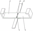
FIG. 1 is a schematic front perspective view of the present invention;
FIG. 2 is a schematic side view of the present invention;
FIG. 3 is an enlarged view of the structure at A in FIG. 2 according to the present invention;
FIG. 4 is a schematic front sectional view of the present invention;
FIG. 5 is an enlarged view of the structure at B in FIG. 4 according to the present invention;
fig. 6 is a schematic view of a clamping frame installation three-dimensional structure of the utility model.
In the figure: 1. a work table; 2. a U-shaped chute; 3. a first clamping frame; 4. an electro-hydraulic lever; 5. a second clamping frame; 6. a U-shaped frame; 7. a screw rod; 8. a pulley; 9. a belt; 10. a moving block; 11. a driving cylinder; 12. mounting blocks; 13. a copper bar; 14. cutting a line; 15. a transfer platform; 16. a limiting strip; 17. a second motor; 18. a rotating shaft; 19. a support plate; 20. a gear; 21. a rack; 22. a first motor; 23. a drum; 24. positioning the platform; 25. positioning a plate; 26. mounting a plate; 27. a threaded post; 28. a crank handle.
Detailed Description
The technical solutions in the embodiments of the present invention will be clearly and completely described below with reference to the drawings in the embodiments of the present invention, and it is obvious that the described embodiments are only a part of the embodiments of the present invention, and not all of the embodiments.
Referring to fig. 1 to 6, the present invention provides a technical solution: a polystyrene board line cutting machine comprises a workbench 1, the upper surface of the workbench 1 is provided with a plurality of uniformly distributed cavities, the interiors of the cavities are rotatably connected with a roller 23 through a pin shaft, one side of the roller 23 is exposed out of the upper surface of the workbench 1, the upper surface of the workbench 1 is provided with a U-shaped chute 2, the interior of the U-shaped chute 2 is slidably connected with a first clamping frame 3, the bottom of the workbench 1 is fixedly provided with a second motor 17, the output shaft of the second motor 17 is connected with a rotating shaft 18 through a coupling transmission, the rotating shaft 18 is rotatably connected on a supporting plate 19 through a bearing, the supporting plate 19 is fixedly connected at the bottom of the workbench 1, the middle part of the rotating shaft 18 is connected with a gear 20 through a key transmission, the bottom of the first clamping frame 3 is fixedly connected with a rack 21 meshed with the gear 20, the bottom of the workbench 1 is provided with a square groove matched with the gear 20, two circular grooves are formed in the side surface of a first clamping frame 3, an electric hydraulic rod 4 is fixedly connected inside the circular grooves, a second clamping frame 5 is fixedly connected to the movable end of the electric hydraulic rod 4, two symmetrically-arranged limiting strips 16 are fixedly connected to the side surface of the second clamping frame 5, a limiting groove matched with the limiting strips 16 is formed in the side surface of the first clamping frame 3, the second clamping frame 5, the electric hydraulic rod 4, a gear 20, a rack 21 and a second motor 17 are arranged in a matched mode, when the polyphenyl board clamping device is used, a polyphenyl board is placed on a workbench 1 and placed between the first clamping frame 3 and the second clamping frame 5, the movable end of the electric hydraulic rod 4 is controlled to be shortened, the polyphenyl board is clamped by the first clamping frame 3 and the second clamping frame 5, the second motor 17 is operated, the polyphenyl board moves along with the first clamping frame 3 and the second clamping frame 5, and therefore loading is completed, displacement deviation generated during the loading of the polystyrene board is avoided, so that the cutting size is more accurate; the upper surface of the workbench 1 is fixedly connected with a U-shaped frame 6, two symmetrically arranged lead screws 7 are rotatably connected between the U-shaped frame 6 and the workbench 1 through bearings, a first motor 22 is fixedly installed at the top of the U-shaped frame 6, an output shaft of the first motor 22 is in transmission connection with one lead screw 7 through a coupling, one end of each of the two lead screws 7 is in transmission connection with a belt pulley 8 through a key, the same belt 9 is in transmission connection between the two belt pulleys 8, the middle part of the lead screw 7 is in threaded connection with a moving block 10, the side surface of the moving block 10 is fixedly connected with a driving cylinder 11, the movable end of the driving cylinder 11 is fixedly installed with an installation block 12, the side surface of the installation block 12 is fixedly connected with a copper bar 13, a cutting line 14 is fixedly connected between the two copper bars 13, and the movement tracks of the two driving cylinders 11 are opposite through the arrangement of the driving cylinders 11, the installation block 12, the copper bars 13 and the cutting line 14, the two driving cylinders 11 are enabled to do stretching movement continuously, so that the cutting line 14 does circular movement in a horizontal plane, the cutting is smoother, and the cutting surface is smoother; one side of workstation 1 is provided with conveying platform 15, conveying platform 15's side fixedly connected with positioning platform 24, positioning platform 24's upper surface is provided with the scale mark, the location spout has been seted up at positioning platform 24's top, the inside sliding connection of location spout has locating plate 25, upper surface one side fixedly connected with mounting panel 26 of positioning platform 24, threaded hole has been seted up to mounting panel 26's side, the inside threaded connection of screw hole has screw thread post 27, screw thread post 27's one end is passed through the bearing and is rotated the connection on locating plate 25, screw thread post 27's other end fixedly connected with crank 28, through setting up positioning platform 24, locating plate 25, mounting panel 26, screw thread post 27, crank 28, the scale, rotate crank 28, can remove locating plate 25, according to the scale, can control the size of cutting polyphenyl board size, make this utility model cutting size more accurate.
When in use, the polyphenyl board is placed on the workbench 1, the movable end of the electric hydraulic rod 4 is controlled to be shortened, the first clamping frame 3 and the second clamping frame 5 clamp the polyphenyl board, the power supply of the second motor 17 is switched on, the second motor 17 drives the gear 20 to rotate, the gear 20 drives the rack 21 to move, so that the polyphenyl board moves forwards along with the first clamping frame 3 and the second clamping frame 5, the loading is finished, after the cutting is finished, the movable end of the electric hydraulic rod 4 extends, the polyphenyl board is released, the second motor 17 rotates reversely, the first clamping frame 3 and the second clamping frame 5 are driven to move backwards, the first clamping frame 3 and the second clamping frame 5 clamp the polyphenyl board, the second motor 17 rotates forwards and loads again, the process is repeated, the loading can be finished for a plurality of times without the assistance of workers, the labor force is greatly reduced, the power supply of the driving cylinder 11 is switched on after the loading is finished, make two actuating cylinder 11 endless loop motion that drive, thereby make line of cut 14 continuous round trip movement in the horizontal plane, the power of bar copper 13 is put through simultaneously, heat line of cut 14, make the cutting more smooth, put through the power of first motor 22 again, first motor 22 drives lead screw 7 and rotates, and then drive movable block 10 and move down, thereby drive line of cut 14 and cut the polyphenyl board, rotate crank 28, just can drive locating plate 25 and remove, according to the scale, can control the size of cutting polyphenyl board, the polyphenyl board after the cutting leaves along with conveying platform 15, is withdrawed by the workman again, just can be material loading once more, the cutting.
In conclusion, the device is provided with the first clamping frame 3, the second clamping frame 5, the electric hydraulic rod 4, the gear 20, the rack 21 and the second motor 17 which are matched for use, when in use, the polystyrene board is placed on the workbench 1 and placed between the first clamping frame 3 and the second clamping frame 5, the movable end of the electric hydraulic rod 4 is controlled to be shortened, the polystyrene board is clamped by the first clamping frame 3 and the second clamping frame 5, and the second motor 17 is operated, so that the polystyrene board moves along with the first clamping frame 3 and the second clamping frame 5, thereby completing loading, avoiding displacement deviation generated during loading of the polystyrene board and enabling the cutting size to be more accurate; by arranging the positioning platform 24, the positioning plate 25, the mounting plate 26, the threaded column 27, the crank 28 and the scales, the positioning plate 25 can be moved by rotating the crank 28, and the size of the cut polyphenyl plate can be controlled according to the scales, so that the cutting size of the utility model is more accurate; through setting up drive actuating cylinder 11, installation piece 12, bar copper 13, line of cut 14, make two motion trails that drive actuating cylinder 11 opposite, through making two drive actuating cylinder 11 constantly do concertina movement to make line of cut 14 be cyclic motion in the horizontal plane, when making the cutting, cut more smoothly, the cutting plane is more level and smooth.
The above description is only for the preferred embodiment of the present invention, but the scope of the present invention is not limited thereto, and any person skilled in the art should be considered to be within the technical scope of the present invention, and equivalent alternatives or modifications according to the technical solution of the present invention and the inventive concept thereof should be covered by the scope of the present invention.
Claims (6)
1. The utility model provides a polyphenyl board lines cutting machine, includes workstation (1), its characterized in that: the upper surface of the workbench (1) is provided with a U-shaped sliding chute (2), the inside of the U-shaped sliding chute (2) is connected with a first clamping frame (3) in a sliding manner, the side surface of the first clamping frame (3) is provided with two circular grooves, the insides of the circular grooves are fixedly connected with electric hydraulic rods (4), and the movable ends of the electric hydraulic rods (4) are fixedly connected with a second clamping frame (5); the upper surface of workstation (1) is fixedly connected with U type frame (6), it is connected with lead screw (7) that two symmetries set up, two to rotate through the bearing between U type frame (6) and workstation (1) the one end of lead screw (7) all is connected with band pulley (8) through key drive, two the transmission is connected with same belt (9) between band pulley (8), the middle part threaded connection of lead screw (7) has movable block (10), the side fixedly connected with of movable block (10) drives actuating cylinder (11), the expansion end fixed mounting who drives actuating cylinder (11) has installation piece (12), the side fixedly connected with bar copper (13) of installation piece (12), two fixedly connected with line of cut (14) between bar copper (13), one side of workstation (1) is provided with conveying platform (15).
2. The polystyrene board line cutter of claim 1, wherein: the side face of the second clamping frame (5) is fixedly connected with two symmetrically arranged limiting strips (16), and the side face of the first clamping frame (3) is provided with a limiting groove matched with the limiting strips (16).
3. The polystyrene board line cutter of claim 1, wherein: the bottom fixed mounting of workstation (1) has second motor (17), and the output shaft of second motor (17) is connected with axis of rotation (18) through the shaft coupling transmission, axis of rotation (18) rotate through the bearing and connect on backup pad (19), backup pad (19) fixed connection is in the bottom of workstation (1), the middle part of axis of rotation (18) is connected with gear (20) through the key transmission, the bottom fixedly connected with of first clamp frame (3) and gear (20) engaged with rack (21), the square groove with gear (20) looks adaptation is seted up to the bottom of workstation (1).
4. The polystyrene board line cutter of claim 1, wherein: the top of the U-shaped frame (6) is fixedly provided with a first motor (22), and an output shaft of the first motor (22) is in transmission connection with one of the screw rods (7) through a coupler.
5. The polystyrene board line cutter of claim 1, wherein: the upper surface of workstation (1) is seted up a plurality of evenly distributed's cavity, the inside of cavity is connected with cylinder (23) through the round pin axle rotation, the upper surface of workstation (1) is exposed to one side of cylinder (23).
6. The polystyrene board line cutter of claim 1, wherein: the side fixedly connected with locating platform (24) of conveying platform (15), the upper surface of locating platform (24) is provided with the scale mark, the location spout has been seted up at the top of locating platform (24), the inside sliding connection of location spout has locating plate (25), upper surface one side fixedly connected with mounting panel (26) of locating platform (24), threaded hole has been seted up to the side of mounting panel (26), the internal thread of screw hole is connected with screw thread post (27), the one end of screw thread post (27) is passed through the bearing and is rotated and connect on locating plate (25), the other end fixedly connected with crank (28) of screw thread post (27).
Priority Applications (1)
| Application Number | Priority Date | Filing Date | Title |
|---|---|---|---|
| CN202122263329.5U CN216181276U (en) | 2021-09-18 | 2021-09-18 | Polyphenyl board line cutting machine |
Applications Claiming Priority (1)
| Application Number | Priority Date | Filing Date | Title |
|---|---|---|---|
| CN202122263329.5U CN216181276U (en) | 2021-09-18 | 2021-09-18 | Polyphenyl board line cutting machine |
Publications (1)
| Publication Number | Publication Date |
|---|---|
| CN216181276U true CN216181276U (en) | 2022-04-05 |
Family
ID=80920254
Family Applications (1)
| Application Number | Title | Priority Date | Filing Date |
|---|---|---|---|
| CN202122263329.5U Active CN216181276U (en) | 2021-09-18 | 2021-09-18 | Polyphenyl board line cutting machine |
Country Status (1)
| Country | Link |
|---|---|
| CN (1) | CN216181276U (en) |
Cited By (1)
| Publication number | Priority date | Publication date | Assignee | Title |
|---|---|---|---|---|
| CN116954391A (en) * | 2023-05-10 | 2023-10-27 | 深圳市英浩科实业有限公司 | Wireless mouse based on Bluetooth transmission and assembly equipment thereof |
-
2021
- 2021-09-18 CN CN202122263329.5U patent/CN216181276U/en active Active
Cited By (1)
| Publication number | Priority date | Publication date | Assignee | Title |
|---|---|---|---|---|
| CN116954391A (en) * | 2023-05-10 | 2023-10-27 | 深圳市英浩科实业有限公司 | Wireless mouse based on Bluetooth transmission and assembly equipment thereof |
Similar Documents
| Publication | Publication Date | Title |
|---|---|---|
| CN202367813U (en) | After-loading high-speed computer cut-to-size saw | |
| CN102528939B (en) | Full-automatic longitudinal and transverse multi-cutting-head combined edge trimmer | |
| CN102390063A (en) | Back loading high-speed computer panel saw | |
| CN216181276U (en) | Polyphenyl board line cutting machine | |
| CN207615546U (en) | A kind of automobile door frame inner and outer plates automatic cutting assembly line | |
| CN210189348U (en) | Mould processing grinding device | |
| CN201287173Y (en) | Automatic bending device of bi-directional movement vertical steel bar | |
| CN202448242U (en) | Automatic combined edge trimmer with multiple longitudinal-transverse cutting heads | |
| CN214686868U (en) | Cutting die supply system and high-speed intelligent cutting machining center using same | |
| CN106476082B (en) | A kind of large size lumps of wood sheet machining apparatus | |
| CN115383176A (en) | Punching equipment for elevator track machining | |
| CN213763656U (en) | Punching machine for producing reinforcing ribs of distribution cabinet door | |
| CN202367811U (en) | Boosting mechanism of back-feeding high speed computer cut-to-size saw | |
| CN213471575U (en) | Wooden product mold convenient to fix | |
| CN110834136A (en) | Numerical control cutting system for civil air defense door section bar | |
| CN213829771U (en) | Squaring machine silicon crystal bar clamping device | |
| CN212144321U (en) | Tensile aligning device of construction steel bar | |
| CN113043589A (en) | Multi-track photocuring 3d printer | |
| CN109904995B (en) | Assembly line of automatic wiring machine for motor stator | |
| CN215662096U (en) | Full-automatic plate pressing machine for packing box | |
| CN219852799U (en) | Automatic welding equipment for mechanical arm | |
| CN211362958U (en) | Air exhaust punching device of plastic suction mold | |
| CN214393649U (en) | Material taking device for numerically controlled grinder | |
| CN215698376U (en) | Sliding mechanism of cutting machine for machining agricultural machine accessories | |
| CN219542382U (en) | Clamping device for machining of die milling machine |
Legal Events
| Date | Code | Title | Description |
|---|---|---|---|
| GR01 | Patent grant | ||
| GR01 | Patent grant |