CN216177494U - High-precision touch welding device for production of high-quality reinforcing mesh - Google Patents
High-precision touch welding device for production of high-quality reinforcing mesh Download PDFInfo
- Publication number
- CN216177494U CN216177494U CN202122398387.9U CN202122398387U CN216177494U CN 216177494 U CN216177494 U CN 216177494U CN 202122398387 U CN202122398387 U CN 202122398387U CN 216177494 U CN216177494 U CN 216177494U
- Authority
- CN
- China
- Prior art keywords
- fixed
- rack
- welding device
- close
- motor
- Prior art date
- Legal status (The legal status is an assumption and is not a legal conclusion. Google has not performed a legal analysis and makes no representation as to the accuracy of the status listed.)
- Expired - Fee Related
Links
- 238000003466 welding Methods 0.000 title claims abstract description 67
- 230000003014 reinforcing effect Effects 0.000 title claims abstract description 21
- 238000004519 manufacturing process Methods 0.000 title claims abstract description 18
- 230000007246 mechanism Effects 0.000 claims abstract description 41
- 230000001360 synchronised effect Effects 0.000 claims abstract description 13
- 230000000087 stabilizing effect Effects 0.000 claims description 8
- 229910000831 Steel Inorganic materials 0.000 claims description 5
- 239000010959 steel Substances 0.000 claims description 5
- 238000003825 pressing Methods 0.000 claims description 4
- 230000009467 reduction Effects 0.000 claims description 3
- 239000002184 metal Substances 0.000 description 4
- 238000000034 method Methods 0.000 description 4
- 230000005540 biological transmission Effects 0.000 description 3
- 238000007599 discharging Methods 0.000 description 3
- 238000010586 diagram Methods 0.000 description 2
- 238000006073 displacement reaction Methods 0.000 description 2
- 230000008569 process Effects 0.000 description 2
- 238000004804 winding Methods 0.000 description 2
- 229910001294 Reinforcing steel Inorganic materials 0.000 description 1
- 230000009286 beneficial effect Effects 0.000 description 1
- 230000002146 bilateral effect Effects 0.000 description 1
- 238000010411 cooking Methods 0.000 description 1
- 238000001125 extrusion Methods 0.000 description 1
- 230000006872 improvement Effects 0.000 description 1
- 239000000463 material Substances 0.000 description 1
- 238000012986 modification Methods 0.000 description 1
- 230000004048 modification Effects 0.000 description 1
Images



Landscapes
- Wire Processing (AREA)
Abstract
The utility model provides a high-precision butt-welding device for producing a high-quality reinforcing mesh, which comprises a rack, stand columns, welding devices, conveying belts, a placing groove, a wire arranging mold, a stable clamping mechanism and a synchronous driving mechanism, wherein the two stand columns are symmetrically arranged on two sides of one end of the rack; the utility model can effectively improve the welding efficiency and the welding precision, and is suitable for a large amount of mesh processing and production work of large-scale enterprises.
Description
Technical Field
The utility model relates to the technical field of butt-welding devices, in particular to a high-precision butt-welding device for producing high-quality reinforcing mesh sheets.
Background
In the daily cooking process of people, a metal net rack is often used, and the common metal net rack comprises an outer frame and a net wire arranged in the middle of the outer frame and used for placing food materials. The existing production method of the metal net rack is that production personnel arrange the processed outer frame and the net wires into a metal wire arranging mould in sequence, then the wire arranging mould is arranged in a spot welding device, the production personnel hold two sides of the wire arranging mould respectively with two hands, push the wire arranging mould to move left and right in the spot welding device, and weld the connection points of the outer frame and the net wires one by one until all the connection points are welded, and the production method has very low production efficiency and is easy to hurt workers;
according to an automatic butt-welding device provided by the prior patent CN 107838539A, the device comprises a frame, a working platform, a welding mechanism and a transmission mechanism; the working platform is arranged on the upper end surface of the frame; the welding mechanism is arranged above and/or below the working platform, and a welding station is formed between the welding mechanism and the working platform; the transmission mechanism is movably arranged on the working platform and is provided with a wire arranging die for arranging wires; the wire arranging mould can move on the working platform along with the transmission mechanism and enter a welding station; the welding mechanism is used for welding wires in the flat cable die. Compared with the prior art, the automatic butt-welding device has the advantages of stability, reliability, high automation degree and the like; although the butt-welding device that this patent provided can accomplish the weldment work of net piece, and the precision has had very big improvement than traditional mode, but its production efficiency still very low, is not suitable for the quick processing operation of large-scale processing enterprise's pipelined.
Therefore, it is necessary to provide a new high-precision butt-welding device for producing high-quality steel mesh sheets to solve the above technical problems.
SUMMERY OF THE UTILITY MODEL
In order to solve the technical problem, the utility model provides a high-precision touch welding device for producing high-quality reinforcing mesh sheets.
The utility model provides a high-precision butt-welding device for producing a high-quality reinforcing mesh, which comprises a rack, stand columns, welding devices, conveying belts, a placing groove, a wire arranging mold, a stable clamping mechanism and a synchronous driving mechanism, wherein the two stand columns are symmetrically arranged on two sides of one end of the rack;
stabilize clamping mechanism and include that L type removes frame, spread groove and pivot, two the L type removes the frame and is centrosymmetric sliding connection at the outer wall that the frame is close to stand one end, the spread groove has been seted up at the middle part of L type removal frame one end, the pivot is passed through the bearing and is rotated the inner wall of connecting at the spread groove, and the both ends of pivot all run through the both sides that the spread groove extended to L type removal frame.
Preferably, stabilize clamping mechanism and still including pressing from both sides tight strip, worm wheel, worm and first motor, two press from both sides tight strip symmetry and fix at the both ends of pivot, and press from both sides the surface extrusion contact of tight strip and winding displacement mould, the middle part at the pivot is fixed to the worm wheel, the worm rotates through the bearing to be connected in the L type and removes the one end that the frame is close to the spread groove, and the worm wheel is connected with the worm meshing, first motor is fixed and is removed the one end that the frame is close to the worm at L type, and the one end that the worm is close to first motor is fixed with the output of first motor.
Preferably, synchronous driving mechanism includes linear electric motor, spliced pole, gear and rack plate, linear electric motor fixes in the frame upper end and is close to one side of stand, and linear electric motor's the end of moving and the surface mounting that the frame was removed to an L type of frame one side, the spliced pole passes through the bearing and rotates the middle part of connecting in the frame upper end and being close to stand one side, the lower extreme at the spliced pole is fixed to the gear, the rack plate is fixed and is removed the lower extreme of frame, two at the L type rack plate all is connected with gear engagement.
Preferably, the rack is fixed with the slide rail near the bilateral symmetry of stand one end, one side of L type removal frame is fixed with the draw runner, the outer wall sliding connection of draw runner and slide rail.
Preferably, one side of the upper end of the rack close to the connecting column is fixed with a stabilizing strip, and the bottom of the connecting column is rotatably connected with the stabilizing strip through a bearing.
Preferably, the first motor is a reduction motor.
Preferably, a rubber pad is fixed on one side of the clamping strip.
Preferably, the upper end of the upright column is symmetrically fixed with a reinforcing block, and one side of the reinforcing block is fixed with the outer wall of the welding device.
Compared with the prior art, the high-precision touch welding device for producing the high-quality reinforcing steel bar mesh has the following beneficial effects:
1. according to the utility model, the conveying work of the outer frame and the mesh is carried out by adopting the conveying belt, the two welding devices are arranged, the welding work is simultaneously carried out on the two sides of the mesh, and the conveying belt is used for conveying, so that the welding work is in production line type operation, and the production efficiency is greatly improved compared with the traditional method.
2. The wire arranging mold can be clamped in the placing groove by the stable clamping mechanism, so that the wire arranging mold which is about to reach the welding device can be clamped in the placing groove during welding, the stability of the wire arranging mold can be ensured during welding, the welding can be stably carried out, and the welding quality and the welding precision are ensured.
Drawings
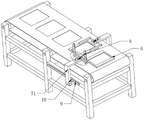
FIG. 1 is a schematic view of the overall structure of the present invention;
FIG. 2 is a schematic structural view of the stabilizing clamping mechanism of the present invention;
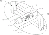
FIG. 3 is an enlarged view of the utility model at A;
FIG. 4 is a schematic structural diagram of a synchronous driving mechanism according to the present invention;
FIG. 5 is a second schematic structural diagram of the synchronous driving mechanism of the present invention.
Reference numbers in the figures: 1. a frame; 2. a column; 3. a welding device; 4. a conveyor belt; 5. a placement groove; 6. a wire arranging mold; 7. a stable clamping mechanism; 71. an L-shaped movable rack; 72. connecting grooves; 73. a rotating shaft; 74. a clamping bar; 75. a worm gear; 76. a worm; 77. a first motor; 8. a synchronous drive mechanism; 81. a linear motor; 82. connecting columns; 83. a gear; 84. a rack plate; 9. a slide rail; 10. a slide bar; 11. a stabilizing strip; 12. a rubber pad; 13. and a reinforcing block.
Detailed Description
In order to make the objects, technical solutions and advantages of the present invention more apparent, the present invention is described in further detail below with reference to the accompanying drawings and embodiments. It should be understood that the specific embodiments described herein are merely illustrative of the utility model and are not intended to limit the utility model.
Specific implementations of the present invention are described in detail below with reference to specific embodiments.
Referring to fig. 1, 2 and 3, a high-precision butt-welding device for producing a high-quality steel mesh sheet according to an embodiment of the present invention includes a frame 1, columns 2, a welding device 3, a conveyor belt 4, a placement groove 5, a wire arranging mold 6, a stable clamping mechanism 7 and a synchronous driving mechanism 8, wherein the two columns 2 are symmetrically disposed at two sides of one end of the frame 1, the top of the upright post 2 is fixed with a welding device 3, the conveyor belt 4 is arranged at the upper end of the frame 1, the placing grooves 5 are equidistantly arranged on the outer surface of the conveyor belt 4, the flat cable mould 6 is sleeved on the inner side of the placing grooves 5, the stable clamping mechanism 7 is connected on the outer wall of one end of the rack 1 in a sliding manner in a central symmetry manner, the synchronous driving mechanism 8 is fixed at one side of the upper end of the frame 1 close to the stable clamping mechanism 7 and is used for driving the stable clamping mechanism 7 to move;
stabilize clamping mechanism 7 and include that L type removes frame 71, spread groove 72 and pivot 73, two L type removes frame 71 and is centrosymmetric sliding connection at the outer wall that frame 1 is close to stand 2 one end, the spread groove 72 has been seted up at the middle part of L type removal frame 71 one end, pivot 73 passes through the bearing and rotates the inner wall of connecting at spread groove 72, and the both ends of pivot 73 all run through the both sides that spread groove 72 extended to L type removal frame 71.
It should be noted that, the conveying belt 4 is used for conveying the outer frame and the mesh, the two welding devices 3 are arranged, the two sides of the mesh are simultaneously welded on the two sides of the mesh, and the conveying belt 4 is used for conveying the mesh, so that the welding operation is in assembly line type operation, and the production efficiency is greatly improved compared with the traditional method.
Referring to fig. 2 and 3, the stable clamping mechanism 7 further includes clamping bars 74, a worm wheel 75, a worm 76 and a first motor 77, the two clamping bars 74 are symmetrically fixed at two ends of the rotating shaft 73, the clamping bars 74 are in pressing contact with the surface of the flat cable mold 6, the worm wheel 75 is fixed at the middle of the rotating shaft 73, the worm 76 is rotatably connected to one end of the L-shaped moving frame 71 close to the connecting groove 72 through a bearing, the worm wheel 75 is in meshed connection with the worm 76, the first motor 77 is fixed at one end of the L-shaped moving frame 71 close to the worm 76, the first motor 77 is a speed reduction motor, and one end of the worm 76 close to the first motor 77 is fixed to an output end of the first motor 77.
It should be noted that, the stable clamping mechanism 7 can be used for clamping the flat cable die 6 which is about to reach the position of the welding device 3 in the placing groove 5 between welding, so that the stability of the flat cable die 6 can be ensured during welding, stable welding can be ensured, and the welding quality and precision are ensured.
Referring to fig. 4 and 5, the synchronous driving mechanism 8 includes a linear motor 81, a connecting column 82, a gear 83 and rack plates 84, the linear motor 81 is fixed on one side of the upper end of the frame 1 close to the upright post 2, the moving end of the linear motor 81 is fixed on the surface of an L-shaped moving frame 71 on one side of the frame 1, the connecting column 82 is rotatably connected to the middle part of the upper end of the frame 1 close to one side of the upright post 2 through a bearing, the gear 83 is fixed at the lower end of the connecting column 82, the rack plates 84 are fixed at the lower end of the L-shaped moving frame 71, and both rack plates 84 are engaged with the gear 83.
It should be noted that the synchronous driving mechanism 8 can drive the two stable clamping mechanisms 7 on the two sides to move in opposite directions simultaneously, so that the stable clamping mechanisms 7 can be moved conveniently to continuously complete the clamping operation of the winding displacement mold 6 on the conveyor belt 4.
Referring to fig. 2, slide rails 9 are symmetrically fixed on two sides of one end of the frame 1 close to the upright post 2, a slide bar 10 is fixed on one side of the L-shaped moving frame 71, and the slide bar 10 is slidably connected with the outer wall of the slide rail 9, so that the L-shaped moving frame 71 can slide stably.
Referring to fig. 5, a stabilizing strip 11 is fixed on one side of the upper end of the frame 1 close to the connecting column 82, and the bottom of the connecting column 82 is rotatably connected with the stabilizing strip 11 through a bearing, so that the stability of the connecting column 82 can be improved.
Referring to fig. 3, a rubber pad 12 is fixed on one side of the clamping strip 74, so as to increase the friction between the clamping strip 74 and the flat cable mold 6.
Referring to fig. 1, the reinforcing blocks 13 are symmetrically fixed to the upper end of the upright 2, and one side of the reinforcing block 13 is fixed to the outer wall of the welding device 3, so that the connection strength between the welding device 3 and the upright 2 can be improved.
The high-precision touch welding device for producing the high-quality reinforcing mesh provided by the utility model has the following working principle:
when the device is used, the outer frame and the reinforcing mesh on the mesh sheet are placed in the flat cable die 6, the flat cable die 6 is sequentially placed in the placing groove 5 from the feeding end of one end, away from the stand column 2, of the conveyor belt 4, the flat cable die 6 is driven to move towards one side of the discharging end by driving the conveyor belt 4 to work, when one flat cable die 6 on the conveyor belt 4 is about to reach the stand column 2, the worm 76 can be driven to rotate by driving the first motor 77 close to one side of the flat cable die 6 to drive the worm gear 75 to rotate, the rotating shaft 73 is driven to rotate, the two clamping strips 74 are driven to be tightly pressed on the surface of the flat cable die 6, the flat cable die 6 is stably clamped in the placing groove 5, the conveyor belt 4 continuously runs at the same time of clamping, the linear motor is driven to simultaneously work, and the L-shaped moving frame 71 on one side of the feeding end slides at the same speed as the conveyor belt 4, and slides to the blanking end, and when the L-shaped moving frame 71 slides, the rack plate 84 at the side can be driven to move, the toggle gear 83 rotates, so that the two rack plates 84 move in opposite directions, and finally the L-shaped moving frame 71 at the other side slides to the feeding end, when the clamped wire arranging mold 6 reaches the lower part of the welding device 3, the welding device 3 performs welding work on the two sides of the outer frame and the reinforcing mesh, and after the mesh in the wire arranging mold 6 is welded, the wire arranging mold 6 reaches the other side of the welding device 3 under the driving of the conveyor belt 4, and the next wire arranging mold 6 just reaches the clamped position, so as to simultaneously drive the two first motors 77 to rotate, and the rotation directions of the two first motors 77 are opposite, so that the clamping strip 74 at one side of the mesh which completes the welding work rotates in the direction separated from the wire arranging mold 6, the clamping strip 74 at one side of the next welded mesh is clamped on the flat cable mould 6, finally the linear motor is driven to work again, and the linear motor is driven to work at the moment to drive the L-shaped moving frame 71 at the position of the discharging end of the conveyor belt 4 to move to the position close to the charging end, and the L-shaped moving frame 71 at the position close to the charging end of the conveyor belt 4 to move to the position close to the discharging end, so that the subsequent mesh welding work is finished in a reciprocating manner;
the utility model can effectively improve the welding efficiency and the welding precision, and is suitable for a large amount of mesh processing and production work of large-scale enterprises.
The circuits and controls involved in the present invention are prior art and will not be described in detail herein.
The above description is only an embodiment of the present invention, and not intended to limit the scope of the present invention, and all modifications of equivalent structures and equivalent processes, which are made by using the contents of the present specification and the accompanying drawings, or directly or indirectly applied to other related technical fields, are included in the scope of the present invention.
Claims (8)
1. The utility model provides a high accuracy bump welding device is used in production of high-quality reinforcing bar net piece which characterized in that includes:
a frame (1);
the two upright posts (2) are symmetrically arranged on two sides of one end of the rack (1), and the welding device (3) is fixed at the top of each upright post (2);
the conveyor belt (4), the conveyor belt (4) is installed at the upper end of the rack (1);
the placing grooves (5) are arranged on the outer surface of the conveyor belt (4) at equal intervals;
the flat cable die (6), the flat cable die (6) is sleeved on the inner side of the placing groove (5);
the stable clamping mechanism (7) is connected to the outer wall of one end of the rack (1) in a sliding manner in a centrosymmetric manner and is used for pressing the flat cable mold (6) in the placing groove (5);
the synchronous driving mechanism (8), the synchronous driving mechanism (8) is fixed on one side of the upper end of the rack (1) close to the stable clamping mechanism (7) and is used for driving the stable clamping mechanism (7) to move;
the stable clamping mechanism (7) comprises:
the two L-shaped moving frames (71) are connected to the outer wall of one end, close to the upright post (2), of the rack (1) in a sliding mode in a centrosymmetric mode;
the middle part of one end of the L-shaped moving frame (71) is provided with a connecting groove (72);
the rotating shaft (73) is rotatably connected to the inner wall of the connecting groove (72) through a bearing, and two ends of the rotating shaft (73) penetrate through the connecting groove (72) and extend to two sides of the L-shaped moving frame (71).
2. The high-precision touch welding device for producing the high-quality steel mesh sheets according to claim 1, wherein the stable clamping mechanism (7) further comprises:
the two clamping strips (74) are symmetrically fixed at two ends of the rotating shaft (73), and the clamping strips (74) are in pressing contact with the surface of the flat cable die (6);
the worm wheel (75), the said worm wheel (75) is fixed in the middle part of the spindle (73);
the worm (76) is rotatably connected to one end, close to the connecting groove (72), of the L-shaped moving frame (71) through a bearing, and the worm wheel (75) is meshed with the worm (76);
the first motor (77), the first motor (77) is fixed at one end of the L-shaped moving frame (71) close to the worm (76), and one end of the worm (76) close to the first motor (77) is fixed with the output end of the first motor (77).
3. The high-precision touch welding device for producing the high-quality steel mesh according to claim 2, wherein the synchronous driving mechanism (8) comprises:
the linear motor (81), the linear motor (81) is fixed on one side of the upper end of the rack (1) close to the upright post (2), and the moving end of the linear motor (81) is fixed with the surface of an L-shaped moving frame (71) on one side of the rack (1);
the connecting column (82) is rotatably connected to the middle of one side, close to the upright post (2), of the upper end of the rack (1) through a bearing;
the gear (83), the said gear (83) is fixed on the bottom end of the joint pin (82);
and the rack plates (84) are fixed at the lower end of the L-shaped moving frame (71), and the two rack plates (84) are meshed and connected with the gear (83).
4. The high-precision touch welding device for the production of the high-quality reinforcing mesh pieces is characterized in that sliding rails (9) are symmetrically fixed to two sides of one end, close to the upright post (2), of the rack (1), a sliding strip (10) is fixed to one side of the L-shaped moving frame (71), and the sliding strip (10) is connected with the outer walls of the sliding rails (9) in a sliding mode.
5. The high-precision touch welding device for the production of the high-quality steel mesh sheets is characterized in that a stabilizing strip (11) is fixed on one side, close to a connecting column (82), of the upper end of the rack (1), and the bottom of the connecting column (82) is rotatably connected with the stabilizing strip (11) through a bearing.
6. The high-precision butt-welding device for producing the high-quality reinforcing mesh piece is characterized in that the first motor (77) is a speed reduction motor.
7. The high-precision touch welding device for the production of the high-quality reinforcing mesh sheets as claimed in claim 2, wherein a rubber pad (12) is fixed on one side of the clamping strip (74).
8. The high-precision touch welding device for the production of the high-quality reinforcing mesh pieces according to claim 1, wherein reinforcing blocks (13) are symmetrically fixed at the upper ends of the upright columns (2), and one sides of the reinforcing blocks (13) are fixed with the outer wall of the welding device (3).
Priority Applications (1)
| Application Number | Priority Date | Filing Date | Title |
|---|---|---|---|
| CN202122398387.9U CN216177494U (en) | 2021-09-30 | 2021-09-30 | High-precision touch welding device for production of high-quality reinforcing mesh |
Applications Claiming Priority (1)
| Application Number | Priority Date | Filing Date | Title |
|---|---|---|---|
| CN202122398387.9U CN216177494U (en) | 2021-09-30 | 2021-09-30 | High-precision touch welding device for production of high-quality reinforcing mesh |
Publications (1)
| Publication Number | Publication Date |
|---|---|
| CN216177494U true CN216177494U (en) | 2022-04-05 |
Family
ID=80859946
Family Applications (1)
| Application Number | Title | Priority Date | Filing Date |
|---|---|---|---|
| CN202122398387.9U Expired - Fee Related CN216177494U (en) | 2021-09-30 | 2021-09-30 | High-precision touch welding device for production of high-quality reinforcing mesh |
Country Status (1)
| Country | Link |
|---|---|
| CN (1) | CN216177494U (en) |
Cited By (1)
| Publication number | Priority date | Publication date | Assignee | Title |
|---|---|---|---|---|
| CN114733698A (en) * | 2022-04-06 | 2022-07-12 | 江苏奇成装配式建材科技有限公司 | Automatic gluing device for production of heat-preservation and decoration integrated board |
-
2021
- 2021-09-30 CN CN202122398387.9U patent/CN216177494U/en not_active Expired - Fee Related
Cited By (2)
| Publication number | Priority date | Publication date | Assignee | Title |
|---|---|---|---|---|
| CN114733698A (en) * | 2022-04-06 | 2022-07-12 | 江苏奇成装配式建材科技有限公司 | Automatic gluing device for production of heat-preservation and decoration integrated board |
| CN114733698B (en) * | 2022-04-06 | 2022-11-22 | 江苏奇成装配式建材科技有限公司 | Automatic gluing device for production of heat-preservation and decoration integrated board |
Similar Documents
| Publication | Publication Date | Title |
|---|---|---|
| CN109261883B (en) | High-performance alloy steel bar continuous forging device | |
| CN206653086U (en) | A kind of steel bar girder carriage | |
| CN111715942A (en) | An automatic tooth opening and threading system and automatic tooth opening and threading process | |
| CN118893413B (en) | Welding fixture for hardware product machining | |
| CN210968265U (en) | Polishing device for automobile part mold | |
| CN203664965U (en) | Full-automatic numerical control positioning forming welding machine for aluminum-clad wood doors and windows | |
| CN117655171A (en) | U-shaped steel strip bending machine with rectangular hoops | |
| CN214184768U (en) | Pipe bender | |
| CN222114307U (en) | High-precision steel cutting device | |
| CN218946749U (en) | Automatic change frock for welding | |
| CN118699785A (en) | A profile component welding device | |
| CN220782847U (en) | Automatic compress tightly handling equipment | |
| CN109904995B (en) | Assembly line of automatic wiring machine for motor stator | |
| CN118635755A (en) | A welding device for steel grid construction and use method thereof | |
| CN117644398A (en) | Intelligent integrated device for copper wire for motor | |
| CN212761938U (en) | High-precision assembling machine for steel structure | |
| CN214976875U (en) | Bending device for manufacturing packaging box | |
| CN216178484U (en) | Panel fixing device for lathe | |
| CN214161967U (en) | An easily adjustable welding roller frame | |
| CN211763328U (en) | A wide-width polymer web laying automatic gathering and feeding device | |
| CN210756087U (en) | Welding table for hardware mould machining | |
| CN220942648U (en) | Four-side straightening machine | |
| CN217777589U (en) | Split die device | |
| CN210756641U (en) | Automatic carrying and clamping device for machining sliding type workpieces | |
| CN214878356U (en) | An automatic transfer material structure |
Legal Events
| Date | Code | Title | Description |
|---|---|---|---|
| GR01 | Patent grant | ||
| GR01 | Patent grant | ||
| CF01 | Termination of patent right due to non-payment of annual fee | ||
| CF01 | Termination of patent right due to non-payment of annual fee |
Granted publication date: 20220405 |