CN216170777U - Novel carbon deposit trapper - Google Patents
Novel carbon deposit trapper Download PDFInfo
- Publication number
- CN216170777U CN216170777U CN202122702062.5U CN202122702062U CN216170777U CN 216170777 U CN216170777 U CN 216170777U CN 202122702062 U CN202122702062 U CN 202122702062U CN 216170777 U CN216170777 U CN 216170777U
- Authority
- CN
- China
- Prior art keywords
- hydraulic cylinder
- cleaning
- collection
- filter
- collection box
- Prior art date
- Legal status (The legal status is an assumption and is not a legal conclusion. Google has not performed a legal analysis and makes no representation as to the accuracy of the status listed.)
- Expired - Fee Related
Links
- OKTJSMMVPCPJKN-UHFFFAOYSA-N Carbon Chemical compound [C] OKTJSMMVPCPJKN-UHFFFAOYSA-N 0.000 title claims abstract description 56
- 229910052799 carbon Inorganic materials 0.000 title claims abstract description 56
- 238000004140 cleaning Methods 0.000 claims abstract description 58
- 238000007789 sealing Methods 0.000 claims description 24
- 238000001914 filtration Methods 0.000 abstract description 6
- UGFAIRIUMAVXCW-UHFFFAOYSA-N Carbon monoxide Chemical compound [O+]#[C-] UGFAIRIUMAVXCW-UHFFFAOYSA-N 0.000 description 8
- 239000003546 flue gas Substances 0.000 description 8
- 238000010586 diagram Methods 0.000 description 6
- 230000000694 effects Effects 0.000 description 3
- CURLTUGMZLYLDI-UHFFFAOYSA-N Carbon dioxide Chemical compound O=C=O CURLTUGMZLYLDI-UHFFFAOYSA-N 0.000 description 2
- 230000000903 blocking effect Effects 0.000 description 2
- 238000000034 method Methods 0.000 description 2
- 239000000779 smoke Substances 0.000 description 2
- 230000009286 beneficial effect Effects 0.000 description 1
- 229910002092 carbon dioxide Inorganic materials 0.000 description 1
- 239000001569 carbon dioxide Substances 0.000 description 1
- 238000005516 engineering process Methods 0.000 description 1
- 238000009776 industrial production Methods 0.000 description 1
- 238000012986 modification Methods 0.000 description 1
- 230000004048 modification Effects 0.000 description 1
Images


Landscapes
- Filtering Of Dispersed Particles In Gases (AREA)
Abstract
本实用新型公开了一种新型积碳捕捉器,包括壳体、过滤板、捕捉液压缸、清理液压缸以及收集箱,所述过滤仓安装于壳体本体上表面,所述清理仓安装于过滤仓一侧表面,收集仓安装于过滤仓另一侧表面,所述过滤板本体一侧表面与第一栏套一侧表面连接,所述第一栏套另一侧表面与过滤仓内部一侧表面连接,所述第二栏套一侧表面与壳体本体一侧表面连接,所述第二栏套另一侧表面与复滤板一侧表面连接。本实用新型为一种新型积碳捕捉器,通过捕捉液压缸本体带动刮板进而带动毛刷将过滤板本体上的积碳刮下,防止积碳过多堵住过滤板,通过清理液压缸本体带动清理板将刮落的积碳推入收集箱,便于积碳的收集利用。
The utility model discloses a novel carbon deposit catcher, which comprises a housing, a filter plate, a capturing hydraulic cylinder, a cleaning hydraulic cylinder and a collection box. One side surface of the silo, the collection silo is installed on the other side surface of the filter silo, the one side surface of the filter plate body is connected with the one side surface of the first fence cover, and the other side surface of the first fence cover is connected to the inner side of the filter silo. Surface connection, one side surface of the second fence sleeve is connected with one side surface of the housing body, and the other side surface of the second fence sleeve is connected with one side surface of the re-filtering plate. The utility model is a novel carbon deposit catcher, which drives the scraper by catching the hydraulic cylinder body and then drives the brush to scrape off the carbon deposit on the filter plate body, so as to prevent the filter plate from being blocked by excessive carbon deposits. Drive the cleaning plate to push the scraped carbon deposits into the collection box, which is convenient for the collection and utilization of carbon deposits.
Description
技术领域technical field
本实用新型涉及一种碳捕捉器,具体是一种新型积碳捕捉器。The utility model relates to a carbon trap, in particular to a novel carbon deposit trap.
背景技术Background technique
碳捕捉含义为将工业生产中的二氧化碳用各种手段捕捉然后储存或者利用的过程。碳捕捉需要用到碳捕捉器,目前市面上的碳捕捉器虽然对积碳的捕捉率较高,但在实际使用中仍存在一些不足。Carbon capture means the process of capturing and then storing or utilizing carbon dioxide in industrial production by various means. Carbon capture requires the use of carbon capture devices. Although the carbon capture devices currently on the market have a high capture rate for carbon deposits, they still have some shortcomings in practical use.
现有的积碳捕捉器的过滤装置长时间使用容易堵塞影响过滤效果,并且捕捉的积碳不便快速进行回收利用,为此,我们提出一种新型积碳捕捉器。The filter device of the existing carbon deposit trap is easy to be blocked when used for a long time, which affects the filtering effect, and the captured carbon deposit is inconvenient to be recycled quickly. Therefore, we propose a new type of carbon deposit trap.
实用新型内容Utility model content
本实用新型的目的在于提供一种新型积碳捕捉器,以解决上述背景技术中提出的问题。The purpose of the present invention is to provide a novel carbon deposit catcher to solve the problems raised in the above background technology.
为实现上述目的,本实用新型提供如下技术方案:To achieve the above object, the utility model provides the following technical solutions:
一种新型积碳捕捉器,包括壳体、过滤板、捕捉液压缸、清理液压缸以及收集箱,所述壳体包括壳体本体、过滤仓、清理仓、收集仓以及进气口,所述进气口一端表面与壳体本体一侧表面连接,所述过滤仓安装于壳体本体上表面,所述清理仓安装于过滤仓一侧表面,所述收集仓安装于过滤仓另一侧表面,所述过滤板包括过滤板本体、第一栏套、第二栏套以及复滤板,所述过滤板本体一侧表面与第一栏套一侧表面连接,所述第一栏套另一侧表面与过滤仓内部一侧表面连接,所述第二栏套一侧表面与壳体本体一侧表面连接,所述第二栏套另一侧表面与复滤板一侧表面连接,所述捕捉液压缸包括捕捉液压缸本体,所述捕捉液压缸本体一侧表面与过滤仓内部上表面连接,所述清理液压缸包括清理液压缸本体以及清理板,所述清理液压缸本体一侧表面与清理仓内部一侧表面,所述清理板一侧表面与清理液压缸本体一端连接,所述收集箱包括收集箱本体与收集口,所述收集箱本体两侧表面与收集仓内部两侧表面连接,所述收集口安装于收集箱本体上表面。A new type of carbon deposit catcher includes a housing, a filter plate, a capturing hydraulic cylinder, a cleaning hydraulic cylinder and a collection box. The housing includes a housing body, a filter chamber, a cleaning chamber, a collection chamber and an air inlet. One end surface of the air inlet is connected to one side surface of the housing body, the filter bin is mounted on the upper surface of the housing body, the cleaning bin is mounted on one side surface of the filter bin, and the collection bin is mounted on the other side surface of the filter bin , the filter plate includes a filter plate body, a first column cover, a second column cover and a multi-filter plate, one side surface of the filter plate body is connected with one side surface of the first column cover, and the first column cover is another The side surface is connected with the inner side surface of the filter chamber, the side surface of the second fence is connected with the one side surface of the shell body, the other side surface of the second fence is connected with the one side surface of the re-filtering plate, the said The catching hydraulic cylinder includes a catching hydraulic cylinder body, one side surface of the catching hydraulic cylinder body is connected to the inner upper surface of the filter bin, the cleaning hydraulic cylinder includes a cleaning hydraulic cylinder body and a cleaning plate, and one side surface of the cleaning hydraulic cylinder body is connected with the inner upper surface of the filter bin. The inner surface of the cleaning bin, the one side surface of the cleaning plate is connected to one end of the cleaning hydraulic cylinder body, the collection box includes a collection box body and a collection port, and the two side surfaces of the collection box body are connected to the inner two sides of the collection bin. , the collection port is installed on the upper surface of the collection box body.
优选地,所述壳体还包括伸缩口以及清理口,所述伸缩口安装于清理仓一侧表面,所述清理口安装于收集仓一侧表面,清理口的作用是便于将积碳推入收集仓。Preferably, the housing further comprises a telescopic port and a cleaning port, the telescopic port is installed on the surface of one side of the cleaning bin, the cleaning port is installed on the surface of one side of the collecting bin, and the function of the cleaning port is to facilitate pushing carbon deposits into collection bin.
优选地,所述过滤板还包括进气管、吸风机以及出气管,所述进气管一端与第一栏套一侧表面连接,所述吸风机一侧表面与进气管另一端表面连接,所述吸风机另一侧表面与出气管一端连接,所述出气管另一端与第二栏套一侧表面连接,过滤板本体的作用是过滤烟气中的积碳,第一栏套与第二栏套的作用是防止漏气,进气管、吸风机以及出气管的作用是将外界的烟气吸入并排出,复滤板的作用是防止烟气未过滤干净。Preferably, the filter plate further comprises an air inlet pipe, a suction fan and an air outlet pipe, one end of the air inlet pipe is connected to one side surface of the first fence, one side surface of the suction fan is connected to the other end surface of the air inlet pipe, the The other side surface of the suction fan is connected to one end of the air outlet pipe, and the other end of the air outlet pipe is connected to one side surface of the second column cover. The function of the filter plate body is to filter the carbon deposits in the flue gas. The first column cover and the second column cover The function of the sleeve is to prevent air leakage. The function of the air intake pipe, the suction fan and the air outlet pipe is to inhale and discharge the outside flue gas. The function of the re-filter plate is to prevent the flue gas from being unfiltered.
优选地,捕捉液压缸还包括刮板以及毛刷,所述刮板一侧表面与捕捉液压缸本体一端连接,所述毛刷一侧表面与刮板一侧表面连接,捕捉液压缸本体的作用是带动刮板以及毛刷上下移动,刮板以及毛刷的作用是将过滤板本体上的积碳刮下防止堵塞。Preferably, the catching hydraulic cylinder further comprises a scraper and a brush, one side surface of the scraper is connected with one end of the catching hydraulic cylinder body, and one side surface of the brush is connected with one side surface of the scraper, and the function of the catching hydraulic cylinder body is It drives the scraper and the brush to move up and down. The function of the scraper and the brush is to scrape off the carbon deposits on the filter plate body to prevent clogging.
优选地,所述清理液压缸还包括封口液压缸以及封口板,所述封口液压缸一侧表面与收集仓内部一侧表面连接,所述封口板一侧表面与封口液压缸一端连接,清理液压缸与清理板的作用是将刮落的积碳推入收集箱本体,封口液压缸以及封口板的作用是堵住清理口防止未过滤的烟气进入收集箱本体。Preferably, the cleaning hydraulic cylinder further includes a sealing hydraulic cylinder and a sealing plate, one side surface of the sealing hydraulic cylinder is connected with a side surface inside the collecting bin, and one side surface of the sealing plate is connected with one end of the sealing hydraulic cylinder, and the cleaning hydraulic The function of the cylinder and the cleaning plate is to push the scraped carbon deposits into the collection box body. The function of the sealing hydraulic cylinder and the sealing plate is to block the cleaning port to prevent the unfiltered flue gas from entering the collection box body.
优选地,所述收集箱还包括箱门以及把手,所述箱门安装于收集箱一侧表面,所述把手一侧表面与箱门一侧表面连接,收集箱本体的作用是收集积碳,收集口的作用是便于积碳落入收集箱本体,箱门以及把手的作用是便于取出收集箱本体内的积碳。Preferably, the collection box further comprises a box door and a handle, the box door is installed on one side surface of the collection box, the one side surface of the handle is connected with the side surface of the box door, and the function of the collection box body is to collect carbon deposits, The function of the collection port is to facilitate the carbon deposits to fall into the collection box body, and the function of the box door and the handle is to facilitate the removal of the carbon deposits in the collection box body.
与现有技术相比,本实用新型的有益效果是:Compared with the prior art, the beneficial effects of the present utility model are:
1、通过设置捉液压缸本体带动刮板进而带动毛刷将过滤板本体上的积碳刮下,防止积碳过多堵住过滤板,进而影响过滤板的过滤效果。1. By setting the hydraulic cylinder body to drive the scraper and then drive the brush to scrape off the carbon deposits on the filter plate body, so as to prevent excessive carbon deposits from blocking the filter plate, thereby affecting the filtering effect of the filter plate.
2、通过清理液压缸本体带动清理板将刮落的积碳推入收集箱,避免人工手动清理,省时省力,便于积碳的收集利用。2. The cleaning plate drives the cleaning plate to push the scraped carbon deposits into the collection box by cleaning the body of the hydraulic cylinder, avoiding manual cleaning, saving time and effort, and facilitating the collection and utilization of carbon deposits.
附图说明Description of drawings
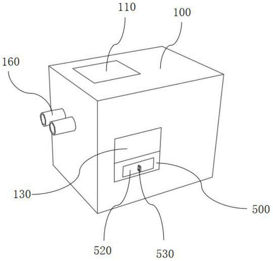
图1为一种新型积碳捕捉器的整体结构示意图;Figure 1 is a schematic diagram of the overall structure of a new type of carbon trap;
图2为一种新型积碳捕捉器的另一实施例的结构示意图;2 is a schematic structural diagram of another embodiment of a novel carbon deposit catcher;
图3为一种新型积碳捕捉器的过滤板的结构示意图;Fig. 3 is a structural schematic diagram of a filter plate of a novel carbon deposit catcher;
图4为一种新型积碳捕捉器的内部结构示意图;Figure 4 is a schematic diagram of the internal structure of a new type of carbon trap;
图5为一种新型积碳捕捉器的另一实施例的内部结构示意图;5 is a schematic diagram of the internal structure of another embodiment of a novel carbon deposit catcher;
图6为一种新型积碳捕捉器的壳体的内部结构示意图。FIG. 6 is a schematic diagram of the internal structure of the shell of a new type of carbon deposit catcher.
图中:100、壳体;110、过滤仓;120、清理仓;130、收集仓;140、伸缩口;150、清理口;160、进气口;200、过滤板;210、第一栏套;220、进气管;230、吸风机;240、出气管;250、第二栏套;260、复滤板;300、捕捉液压缸;310、刮板;320、毛刷;400、清理液压缸;410、清理板;420、封口液压缸;430、封口板;500、收集箱;510、收集口;520、箱门;530、把手。In the figure: 100, shell; 110, filter bin; 120, cleaning bin; 130, collecting bin; 140, telescopic port; 150, cleaning port; 160, air inlet; 200, filter plate; 210, first column cover ;220, intake pipe; 230, suction fan; 240, outlet pipe; 250, second column cover; 260, re-filter plate; 300, catch hydraulic cylinder; 310, scraper; 320, brush; 400, cleaning hydraulic cylinder ; 410, cleaning plate; 420, sealing hydraulic cylinder; 430, sealing plate; 500, collecting box; 510, collecting port; 520, box door; 530, handle.
具体实施方式Detailed ways
下面将结合本实用新型实施例中的附图,对本实用新型实施例中的技术方案进行清楚、完整地描述,显然,所描述的实施例仅仅是本实用新型一部分实施例,而不是全部的实施例。基于本实用新型中的实施例,本领域普通技术人员在没有做出创造性劳动前提下所获得的所有其他实施例,都属于本实用新型保护的范围。The technical solutions in the embodiments of the present utility model will be clearly and completely described below with reference to the accompanying drawings in the embodiments of the present utility model. Obviously, the described embodiments are only a part of the embodiments of the present utility model, rather than all the implementations. example. Based on the embodiments of the present invention, all other embodiments obtained by those of ordinary skill in the art without creative work fall within the protection scope of the present invention.
请参阅图1~6,本实用新型实施例中,一种新型积碳捕捉器,包括壳体100、过滤板200、捕捉液压缸300、清理液压缸400以及收集箱500,壳体100包括壳体本体、过滤仓110、清理仓120、收集仓130以及进气口160,进气口160一端表面与壳体本体一侧表面连接,过滤仓110安装于壳体本体上表面,清理仓120安装于过滤仓110一侧表面,收集仓130安装于过滤仓110另一侧表面,过滤板200包括过滤板本体、第一栏套210、第二栏套250以及复滤板260,过滤板本体一侧表面与第一栏套210一侧表面连接,第一栏套210另一侧表面与过滤仓110内部一侧表面连接,第二栏套250一侧表面与壳体本体一侧表面连接,第二栏套250另一侧表面与复滤板260一侧表面连接,捕捉液压缸300包括捕捉液压缸本体,捕捉液压缸本体一侧表面与过滤仓110内部上表面连接,清理液压缸400包括清理液压缸本体以及清理板410,清理液压缸本体一侧表面与清理仓120内部一侧表面,清理板410一侧表面与清理液压缸本体一端连接,收集箱500包括收集箱本体与收集口510,收集箱本体两侧表面与收集仓130内部两侧表面连接,收集口510安装于收集箱本体上表面。Referring to FIGS. 1 to 6 , in an embodiment of the present invention, a novel carbon deposit catcher includes a
其中,壳体100还包括伸缩口140以及清理口150,伸缩口140安装于清理仓120一侧表面,清理口150安装于收集仓130一侧表面,清理口150的作用是便于将积碳推入收集仓130。The
其中,过滤板200还包括进气管220、吸风机230以及出气管240,进气管220一端与第一栏套210一侧表面连接,吸风机230一侧表面与进气管220另一端连接,吸风机230另一侧表面与出气管240一端连接,出气管240另一端与第二栏套250一侧表面连接,过滤板本体的作用是过滤烟气中的积碳,第一栏套210与第二栏套250的作用是防止漏气,进气管220、吸风机230以及出气管240的作用是将外界的烟气吸入并排出,复滤板260的作用是防止烟气未过滤干净。The
其中,捕捉液压缸300还包括刮板310以及毛刷320,刮板310一侧表面与捕捉液压缸本体一端连接,毛刷320一侧表面与刮板310一侧表面连接,捕捉液压缸本体的作用是带动刮板310以及毛刷320上下移动,刮板310以及毛刷320的作用是将过滤板本体上的积碳刮下防止堵塞。The capturing
其中,清理液压缸400还包括封口液压缸420以及封口板430,封口液压缸420一侧表面与收集仓130内部一侧表面连接,封口板430一侧表面与封口液压缸420一端连接,清理液压缸400与清理板410的作用是将刮落的积碳推入收集箱本体,封口液压缸420以及封口板430的作用是堵住清理口150防止未过滤的烟气进入收集箱本体。The cleaning
其中,收集箱500还包括箱门520以及把手530,箱门520安装于收集箱500一侧表面,把手530一侧表面与箱门520一侧表面连接,收集箱本体的作用是收集积碳,收集口510的作用是便于积碳落入收集箱本体,箱门520以及把手530的作用是便于取出收集箱本体内的积碳。The
本实用新型的工作原理是:The working principle of the utility model is:
其中,捕捉液压缸本体、清理液压缸本体、封口液压缸420的型号均为JRC-1T,工作时吸风机230通过进气口160将烟气吸入过滤仓110,烟气通过过滤板本体进入进气管220、吸风机230与出气管240,经过复滤板260过滤后排出,通过捕捉液压缸本体带动刮板310进而带动毛刷320将过滤板本体上的积碳刮下,防止积碳过多堵住过滤板本体影响过滤效果,积碳落入过滤仓110底部后,通过封口液压缸420带动封口板430脱离清理口150,以便积碳进入收集箱500,通过清理液压缸本体带动清理板410通过伸缩口140进入过滤仓110,将过滤仓110底部的积碳通过清理口150推入收集口510,进而推入收集箱本体,便于积碳的收集利用。Among them, the models for capturing the hydraulic cylinder body, cleaning the hydraulic cylinder body, and sealing
尽管参照前述实施例对本实用新型进行了详细的说明,对于本领域的技术人员来说,其依然可以对前述各实施例所记载的技术方案进行修改,或者对其中部分技术特征进行等同替换,凡在本实用新型的精神和原则之内,所作的任何修改、等同替换、改进等,均应包含在本实用新型的保护范围之内。Although the present invention has been described in detail with reference to the foregoing embodiments, for those skilled in the art, it is still possible to modify the technical solutions described in the foregoing embodiments, or perform equivalent replacements for some of the technical features. Within the spirit and principle of the present utility model, any modifications, equivalent replacements, improvements, etc. made shall be included within the protection scope of the present utility model.
Claims (6)
Priority Applications (1)
| Application Number | Priority Date | Filing Date | Title |
|---|---|---|---|
| CN202122702062.5U CN216170777U (en) | 2021-11-06 | 2021-11-06 | Novel carbon deposit trapper |
Applications Claiming Priority (1)
| Application Number | Priority Date | Filing Date | Title |
|---|---|---|---|
| CN202122702062.5U CN216170777U (en) | 2021-11-06 | 2021-11-06 | Novel carbon deposit trapper |
Publications (1)
| Publication Number | Publication Date |
|---|---|
| CN216170777U true CN216170777U (en) | 2022-04-05 |
Family
ID=80903716
Family Applications (1)
| Application Number | Title | Priority Date | Filing Date |
|---|---|---|---|
| CN202122702062.5U Expired - Fee Related CN216170777U (en) | 2021-11-06 | 2021-11-06 | Novel carbon deposit trapper |
Country Status (1)
| Country | Link |
|---|---|
| CN (1) | CN216170777U (en) |
-
2021
- 2021-11-06 CN CN202122702062.5U patent/CN216170777U/en not_active Expired - Fee Related
Similar Documents
| Publication | Publication Date | Title |
|---|---|---|
| CN118059597A (en) | Smoke exhaust fire prevention valve with filtering capability | |
| CN209612454U (en) | A kind of fountain dedusting deodorizing device | |
| CN212188274U (en) | Dust remover arrangement device of bale breaker | |
| CN208097698U (en) | A kind of construction dust-extraction unit | |
| CN210097267U (en) | A multi-stage easy-to-use dust removal device | |
| CN219964398U (en) | Dust collecting equipment for building construction | |
| CN205760503U (en) | A coal-fired desulfurization device | |
| CN212188265U (en) | An anti-clogging slag discharge device for desulfurization and denitrification in environmental protection projects | |
| CN216604441U (en) | A dust removal device for quicklime discharge | |
| CN216703693U (en) | A coke particle adsorption device for flue gas treatment | |
| CN211215914U (en) | A dust removal device for desulfurization and denitrification | |
| CN115671934A (en) | A smoke and dust removal device for plateau tunnel construction | |
| CN219616343U (en) | An Automatically Adjustable Intelligent Dust Collector | |
| CN217939577U (en) | Dust removal equipment for incineration station | |
| CN211411391U (en) | Dust collector for clean area of pharmaceutical workshop | |
| CN219539810U (en) | Dust catcher | |
| CN222677502U (en) | A coal combustion dust and smoke treatment equipment | |
| CN206240212U (en) | A kind of water curtain for dust-collecting device | |
| CN218608667U (en) | Efficient oil-gas separation device of air compressor | |
| CN221085176U (en) | Malodorous waste gas treatment device | |
| CN219333593U (en) | Filter structure of dust remover | |
| CN222550576U (en) | A desulfurization circulation pump with a catalytic device | |
| CN217287587U (en) | New flue gas denitrification treatment equipment | |
| CN220990073U (en) | A silica gel production dust treatment equipment | |
| CN223144927U (en) | Welding smoke dust collector |
Legal Events
| Date | Code | Title | Description |
|---|---|---|---|
| GR01 | Patent grant | ||
| GR01 | Patent grant | ||
| CF01 | Termination of patent right due to non-payment of annual fee |
Granted publication date: 20220405 |
|
| CF01 | Termination of patent right due to non-payment of annual fee |