Commercial vehicle mechanical parking equipment
Technical Field
The utility model relates to the technical field of stereo garages, in particular to a mechanical parking device for commercial vehicles.
Background
With the continuous promotion of industrialization and urbanization construction in China, commercial vehicles grow rapidly, but because of the shortage of land resources, the original plane parking lot can not meet the parking of the commercial vehicles gradually, and the development of mechanical parking equipment by utilizing upper-layer space becomes an important solution.
The current mechanical parking equipment for commercial vehicles only aims at city buses such as garages, and cannot meet commercial vehicles such as long-distance buses, tourism buses, trucks, full-trailer tractors, special operation vehicles and special trucks, the problem solving range is small, and the application performance is poor.
At present, most of three-dimensional garages are of plane movement type and roadway stacking type, and are low in storing and taking efficiency and large in occupied area.
SUMMERY OF THE UTILITY MODEL
An embodiment of the present invention provides a mechanical parking device for a commercial vehicle, so as to solve at least one of the problems mentioned in the background art.
A commercial vehicle mechanical parking device comprises a traction lifting mechanism, a lifting platform mechanism and a vehicle carrying plate storing and taking mechanism; the traction lifting system comprises a main frame, a steel wire rope, a traction mechanism arranged on the main frame and a lifting platform mechanism which slides up and down in the main frame through the traction mechanism, wherein the traction mechanism comprises a lifting motor and a speed reducer which are fixedly connected to the top of the main frame, an output shaft of the lifting motor is connected with transmission shafts, the transmission shafts are symmetrically arranged on two sides of the lifting motor, and each transmission shaft is connected with a traction wheel through the speed reducer; two corners in front of the top of the main frame are respectively provided with a first guide wheel, four corners at the top of the main frame are respectively provided with a third guide wheel, the top of the main frame is fixedly connected with a traction wheel seat, and the traction wheel seat is provided with a second guide wheel and a traction wheel;
the lifting platform mechanism comprises a lifting frame, the middle part of the lifting frame is provided with a transverse transfer mechanism for transversely moving the vehicle carrying plate, and the upper part of one end of the lifting frame is fixedly connected with the vehicle loading and unloading platform; four corners of the lifting frame are respectively provided with a lifting guide mechanism, and the lifting frame is connected with the main frame in a sliding manner through the lifting guide mechanisms; the middle part of the lifting frame is provided with a leveling safety mechanism, the leveling safety mechanism comprises a speed reducing motor which is connected to the lifting frame in a specified mode, the output end of the speed reducing motor is connected with a connecting piece, two ends of the connecting piece are respectively hinged with one end of two connecting shafts, the other end of each connecting shaft is hinged with a pin shaft, and the pin shaft is connected with the lifting frame in a horizontal sliding mode; the main frame is provided with a plurality of shaft inserting pin holes matched with the shaft inserting pins for use; a platform lifting movable pulley is arranged on the lifting frame, one end of the main frame is connected with a balancing weight matched with the lifting frame in a sliding manner, a counterweight lifting movable pulley is arranged at the top of the balancing weight, and the platform lifting movable pulley and the counterweight lifting movable pulley are connected through a steel wire rope;
the car carrying plate storing and taking mechanism comprises a car carrying plate, a transverse moving motor fixedly connected to the bottom of the lifting frame, a driving chain wheel, a driven chain wheel, a transmission shaft, a double-row transmission chain and a hook pull pin, wherein the driving chain wheel and the driven chain wheel are rotatably connected to the lifting frame; and shifting forks matched with the hook pull pins for use are fixedly connected to two sides of the bottom of the car carrying plate.
Furthermore, the traction lifting system comprises 8 steel wire ropes, one end of each steel wire rope is connected to the top of the main frame, and the other end of each steel wire rope sequentially winds around the balance weight lifting movable pulley, the first guide pulley, the traction sheave and the second guide pulley; wherein 4 wire ropes stretch out to the place ahead and wind behind the third leading wheel of front side and the platform lift movable pulley in the place ahead in proper order fixed connection at the top of main frame, and remaining 4 wire ropes stretch out behind the platform lift movable pulley behind the third leading wheel of passing behind side and the platform lift movable pulley in the rear side in proper order and fixed connection at the top of main frame. .
Furthermore, the lifting guide mechanism comprises a supporting pipe fixedly connected to the lifting frame, symmetrical pulley blocks are respectively arranged at the upper end and the lower end of the supporting pipe, each pulley block comprises two sets of pulleys, and rotating shafts of the two sets of pulleys form a right angle.
Furthermore, be equipped with the lateral pulley group of multirow horizontal parallel arrangement on the lift frame, the lateral pulley group is 3 groups, and the equidistance is installed on the upper surface of lift frame.
Further, the second guide wheel is positioned in the middle of the top of the main frame; the transmission shaft is connected with the speed reducer through a brake wheel coupler, and an electric hydraulic drum brake is arranged on the brake wheel coupler.
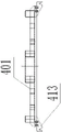
Furthermore, the main frame includes 4 vertical parallel arrangement's guide rail, and 4 angles of lift platform are provided with the guiding mechanism who uses with the guide rail cooperation respectively, lift platform passes through guiding mechanism and slides from top to bottom on the guide rail.
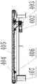
Furthermore, the transverse transfer mechanism also comprises two couplers, the double-row transmission chains, the transmission shafts, the driving chain wheels and the driven chain wheels are in two sets and rotate synchronously, the transverse movement speed reducing motor is connected with the two couplers, each coupler is connected with one transmission shaft, and each transmission shaft is connected with each driving chain wheel; the transverse transfer mechanism further comprises a plurality of chain supporting plates and two chain supporting wheels, the chain supporting plates are arranged below the double-row transmission chains, and the chain supporting wheels are arranged on two sides of the chain supporting plates.
The utility model has the following beneficial effects:
compared with the lifting mode of chain and chain wheel transmission in the prior art, the lifting mechanism has the characteristics of large lifting height, safety, reliability, stable and reliable operation and low noise. According to the utility model, the steel wire rope is wound out of the traction wheel and the second guide wheel and then divided into a front direction and a rear direction, and the stress on the two sides is balanced, so that the stress of the traction wheel seat is reduced, and the defect that the part is easy to damage due to overlarge stress is avoided. The second guide wheel is arranged in the middle of the top of the main frame, so that the lengths of the front and rear lifting steel wire ropes are equal, the extension lengths of the steel wire ropes are also equal under the load condition, and the possibility of front and rear inclination of the lifting platform caused by different lengths of the steel wire ropes is avoided. The mode of putting in the traction mechanism is rational in structure, the whole stress is relatively dispersed, and the stability of the equipment is improved.
According to the lifting platform mechanism, the connecting piece is driven to rotate through the speed reducing motor, and the connecting shaft is pulled and pushed to realize the pulling and inserting actions of the inserting shaft pin when the connecting piece rotates, so that the safety of a lifting frame is improved, and the falling accident is prevented. The lifting guide mechanism comprises a supporting pipe fixedly connected to the lifting frame, symmetrical pulley blocks are arranged at the upper end and the lower end of the supporting pipe respectively, and the lifting platform is connected with the main body frame in a sliding mode through the lifting guide mechanism, so that the stability and the stationarity of the lifting frame during ascending and descending are improved.
The vehicle carrying plate storing and taking mechanism completes the operation of storing and taking the vehicle carrying plates by the hook pull pin and the shifting fork which are matched with the vehicle carrying plates to transversely move, has simple structure, low manufacturing cost, quick operation, stable operation and low failure rate, and improves the efficiency of storing and taking the vehicles in the garage. The lifting frame is provided with a plurality of rows of lateral pulley blocks which are transversely arranged in parallel, the lateral pulley blocks are 3 groups, the lateral pulley blocks are equidistantly arranged on the upper surface of the lifting frame, the structure can increase the contact area with the vehicle carrying plate, and the stability and the stationarity of the vehicle carrying plate during transverse sliding are improved.
Drawings
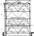
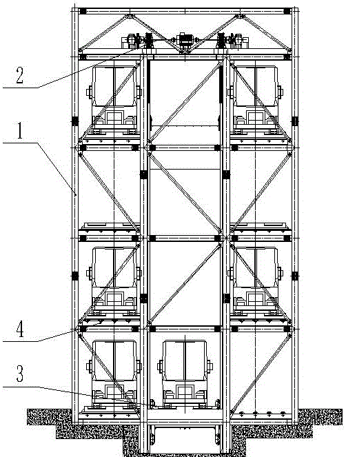
FIG. 1 is a schematic front view of the present invention;
FIG. 2 is a schematic diagram of the right-hand side view of the present invention;
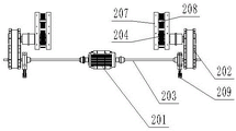
fig. 3 is a front view schematically showing the construction of the traction lifting mechanism according to the present invention;
fig. 4 is a left side view schematically showing the construction of the traction lifting mechanism according to the present invention;
fig. 5 is a schematic top view of the traction lifting mechanism of the present invention;
fig. 6 is an enlarged schematic view of the structure of the traction mechanism in the present invention;
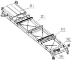
FIG. 7 is a schematic perspective view of the elevating platform mechanism of the present invention;
FIG. 8 is a schematic front view of the elevating platform mechanism of the present invention;
FIG. 9 is a schematic top view of the elevating platform mechanism of the present invention;
FIG. 10 is a left side view of the elevating platform mechanism of the present invention;
FIG. 11 is a perspective view of the lift guide mechanism of the present invention;
FIG. 12 is a schematic top view of the lift guide mechanism of the present invention;
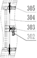
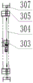
FIG. 13 is an enlarged partial schematic view of the flat bed safety mechanism of the present invention;
FIG. 14 is a schematic left side view of the structure of FIG. 13;
FIG. 15 is a schematic front view of a vehicle loading board storing and taking mechanism according to the present invention;
FIG. 16 is a schematic structural view of a vehicle carrying board in the utility model;
FIG. 17 is a schematic top view of the lateral transfer mechanism of the present invention;
FIG. 18 is a schematic view of the right side structure of FIG. 17;
fig. 19 is an enlarged schematic view of the structure at a in fig. 17.
In the figure: 1-a main frame; 2-dragging and lifting mechanism; 201-a lifting motor; 202-a speed reducer; 203-a transmission shaft; 204-a traction sheave; 205-a first guide wheel; 206-a third guide wheel; 207-a second guide wheel; 208-a traction wheel seat; 209-electro-hydraulic drum brake; 3-a lifting platform mechanism; 301-a lifting frame; 302-locking the gear motor; 303-a connector; 304-a connecting shaft; 305-a pintle pin; 306-a lift guide mechanism; 3061-supporting tube; 3062-pulley block; 307-shaft pin hole; 308-a platform lifting movable pulley; 309-counterweight block; 310-counterweight lifting movable pulley; 311-steel wire rope; 4-vehicle carrying plate storing and taking mechanism; 401-vehicle carrying plate; 402-traverse deceleration motor; 403-a drive sprocket; 404-double rows of drive chains; 405-chain pallets; 406-chain riding wheels; 407-driven sprocket; 408-a coupling; 409-a transmission shaft; 410-hook pull pin; 411-getting on and off platform, 412-lateral pulley block; 413-shifting fork.
Detailed Description
Reference will now be made in detail to embodiments of the present invention, examples of which are illustrated in the accompanying drawings. The embodiments described below with reference to the drawings are illustrative and intended to be illustrative of the utility model and are not to be construed as limiting the utility model.
In the following embodiments, the upper side in fig. 5 is the front side, and the lower side is the rear side.
As shown in fig. 1-19, a mechanical parking device for commercial vehicles comprises a traction lifting mechanism, a lifting platform mechanism and a vehicle carrying board storing and taking mechanism; the traction lifting system comprises a main frame, a steel wire rope, a traction mechanism arranged on the main frame and a lifting platform mechanism which slides up and down in the main frame through the traction mechanism, wherein the traction mechanism comprises a lifting motor and a speed reducer which are fixedly connected to the top of the main frame, an output shaft of the lifting motor is connected with transmission shafts, the transmission shafts are symmetrically arranged on two sides of the lifting motor, and each transmission shaft is connected with a traction wheel through the speed reducer; two corners in front of the top of the main frame are respectively provided with a first guide wheel, four corners at the top of the main frame are respectively provided with a third guide wheel, the top of the main frame is fixedly connected with a traction wheel seat, and the traction wheel seat is provided with a second guide wheel and a traction wheel;
the lifting platform mechanism comprises a lifting frame, the middle part of the lifting frame is provided with a transverse transfer mechanism for transversely moving the vehicle carrying plate, and the upper part of one end of the lifting frame is fixedly connected with the vehicle loading and unloading platform; four corners of the lifting frame are respectively provided with a lifting guide mechanism, and the lifting frame is connected with the main frame in a sliding manner through the lifting guide mechanisms; the middle part of the lifting frame is provided with a leveling safety mechanism, the leveling safety mechanism comprises a locking speed reducing motor which is connected to the lifting frame in a specified mode, the output end of the locking speed reducing motor is connected with a connecting piece, two ends of the connecting piece are respectively hinged with one end of two connecting shafts, the other end of each connecting shaft is hinged with a pin shaft, and the pin shaft is connected with the lifting frame in a horizontal sliding mode; the main frame is provided with a plurality of shaft inserting pin holes matched with the shaft inserting pins for use; a platform lifting movable pulley is arranged on the lifting frame, one end of the main frame is connected with a balancing weight matched with the lifting frame in a sliding manner, a counterweight lifting movable pulley is arranged at the top of the balancing weight, and the platform lifting movable pulley and the counterweight lifting movable pulley are connected through a steel wire rope;
the car carrying plate storing and taking mechanism comprises a car carrying plate, a transverse moving motor fixedly connected to the bottom of the lifting frame, a driving chain wheel, a driven chain wheel, a transmission shaft, a double-row transmission chain and a hook pull pin, wherein the driving chain wheel and the driven chain wheel are rotatably connected to the lifting frame; and shifting forks matched with the hook pull pins for use are fixedly connected to two sides of the bottom of the car carrying plate.
The traction lifting system comprises 8 steel wire ropes, one ends of the steel wire ropes are connected to the top of the main frame, and the other ends of the steel wire ropes sequentially pass through the balance weight lifting movable pulley, the first guide pulley, the traction sheave and the second guide pulley in a winding manner; wherein 4 wire ropes stretch out to the place ahead and wind behind the third leading wheel of front side and the platform lift movable pulley in the place ahead in proper order fixed connection at the top of main frame, and remaining 4 wire ropes stretch out behind the platform lift movable pulley behind the third leading wheel of passing behind side and the platform lift movable pulley in the rear side in proper order and fixed connection at the top of main frame. .
The lifting guide mechanism comprises a supporting pipe fixedly connected to the lifting frame, symmetrical pulley blocks are respectively arranged at the upper end and the lower end of the supporting pipe, each pulley block comprises two sets of pulleys, and rotating shafts of the two sets of pulleys form a right angle.
The lifting frame is provided with a plurality of rows of lateral pulley blocks which are transversely arranged in parallel, the number of the lateral pulley blocks is 3, and the lateral pulley blocks are equidistantly arranged on the upper surface of the lifting frame.
The second guide wheel is positioned in the middle of the top of the main frame; the transmission shaft is connected with the speed reducer through a brake wheel coupler, and an electric hydraulic drum brake is arranged on the brake wheel coupler.
The main frame includes 4 vertical parallel arrangement's guide rail, and 4 angles of lift platform are provided with the guiding mechanism who uses with the guide rail cooperation respectively, lift platform passes through guiding mechanism and slides from top to bottom on the guide rail.
The transverse transfer mechanism also comprises two couplers, the double-row transmission chains, the transmission shafts, the driving chain wheels and the driven chain wheels are in two sets and synchronously rotate, the transverse movement speed reducing motor is connected with the two couplers, each coupler is respectively connected with one transmission shaft, and each transmission shaft is connected with each driving chain wheel; the transverse transfer mechanism further comprises a plurality of chain supporting plates and two chain supporting wheels, the chain supporting plates are arranged below the double-row transmission chains, and the chain supporting wheels are arranged on two sides of the chain supporting plates.
The working process of the utility model is as follows:
before operation, the plug pin is in a retraction state. When the vehicle is stored, the vehicle drives into the vehicle carrying plate, the transverse speed reducing motor is started to drive the two transmission shafts to synchronously rotate, the transmission shafts drive the driving chain wheels to rotate, the driving chain wheels drive the double-row transmission chain to transmit, the hook pull pin is inserted into the shifting fork on the left side of the vehicle carrying plate during rotation, the double-row transmission chain continuously transmits to push the vehicle carrying plate to the lifting frame, and at the moment, the hook pull pin is moved out of the shifting fork. When the vehicle carrying plate moves, the lateral pulley group plays a supporting role for the vehicle carrying plate, and meanwhile, the friction force between the vehicle carrying plate and the lifting platform mechanism is reduced. The locking speed reducing motor rotates reversely to drive the connecting piece to rotate reversely, the connecting piece drives the connecting shaft to retract, and the connecting shaft drives the plug pin shaft to be pulled out from the plug pin hole in the main body frame. The lifting motor is started in the forward direction to drive the transmission shaft to rotate together, the transmission shaft drives the traction sheave to rotate, the traction sheave synchronously retracts 8 steel wire ropes, the lifting platform slides upwards stably and horizontally along the guide rail at the moment, and the lifting motor stops working when the lifting platform ascends to a required position. The locking speed reduction motor drives the connecting piece to rotate, the connecting piece drives the connecting shaft to extend out of two sides of the lifting frame, and the connecting shaft drives the inserting shaft pin to be inserted into the inserting shaft pin hole in the main body frame to lock the lifting frame.
The transverse shifting speed reducing motor is started to drive the two transmission shafts to synchronously rotate, the transmission shafts drive the driving chain wheel to rotate, the driving chain wheel drives the double-row transmission chain to transmit, the hook pull pin is inserted into the shifting fork on the left side of the car carrying plate during rotation, the double-row transmission chain continues to transmit to push the car carrying plate to a parking space, and at the moment, the hook pull pin is moved out of the shifting fork. The locking speed reducing motor rotates reversely to drive the connecting piece to rotate reversely, the connecting piece drives the connecting shaft to retract, and the connecting shaft drives the plug pin shaft to be pulled out from the plug pin hole in the main body frame. When the lifting platform needs to descend, the lifting motor is started reversely to drive the transmission shaft to rotate reversely and simultaneously, the transmission shaft drives the traction wheel to rotate reversely, the traction wheel synchronously loosens 8 steel wire ropes, and at the moment, the lifting platform slides downwards along the guide rail stably and horizontally.
Although embodiments of the present invention have been shown and described above, it is understood that the above embodiments are exemplary and should not be construed as limiting the present invention, and that variations, modifications, substitutions and alterations can be made to the above embodiments by those of ordinary skill in the art within the scope of the present invention.