Novel electric vehicle charging pile of over-and-under type
Technical Field
The utility model relates to the field of electric vehicle charging piles, in particular to a novel lifting type electric vehicle charging pile.
Background
The charging pile has the function similar to an oiling machine in a gas station, can be fixed on the ground or on the wall, is installed in public buildings (public buildings, shopping malls, public parking lots and the like) and residential area parking lots or charging stations, can charge electric vehicles of various types according to different voltage levels, has an input end directly connected with an alternating current power grid, and has an output end provided with a charging plug for charging the electric vehicles, generally provides two charging modes of conventional charging and quick charging, people can use a specific charging card to swipe the card on a human-computer interaction operation interface provided by the charging pile for use, and performs operations such as corresponding charging mode, charging time, cost data printing and the like, and a display screen of the charging pile can display data such as charging quantity, cost, charging time and the like; the electric vehicle charging pile has the advantages that the existing electric vehicle charging pile has certain defects when in use, the urban land cost is high, large-area land resources can be consumed by the large-scale building of the charging pile, the electric vehicle charging pile is damaged due to the fact that the lifting type internal lifting motor can lose efficacy and fall quickly in the long-time use process, a power line is exposed to the outside and is easy to damage, and therefore the novel lifting type electric vehicle charging pile is provided.
SUMMERY OF THE UTILITY MODEL
The utility model mainly aims to provide a novel lifting type electric vehicle charging pile which can effectively solve the problems in the background technology.
In order to achieve the purpose, the utility model adopts the technical scheme that:
the utility model provides a novel electric motor car of over-and-under type fills electric pile, includes the mounting groove, the inside movable mounting of mounting groove has the lift to fill electric pile, the lift fills electric pile both sides fixed surface and installs spacing connection piece, the lift fills electric pile positive fixed surface and has seted up the recess that charges, the lift fills electric pile up end fixed mounting and has waterproof support upper cover, the fixed controller that has seted up in mounting groove one side, the inside lower surface edge fixed position that is close to of mounting groove installs motor power, the inside fixed mounting of recess that charges has the spooler, the inside movable mounting of spooler has the drum.
Preferably, the upper end face of the mounting groove is fixedly provided with a sewage collecting groove, the sewage collecting groove is fixedly provided with a sewage discharge groove, and the two sides of the mounting groove are fixedly provided with limiting fixing grooves.
Preferably, the lifting charging pile lower end face is provided with a threaded concave hole close to the center, and displacement pulleys are movably mounted on the outer surfaces of two sides of the limiting connecting sheet.
Preferably, the touch display is fixedly mounted inside the charging groove, the waterproof rubber pad is fixedly mounted on the lower surface of the upper waterproof support cover, the master control power supply box is fixedly mounted inside the controller, and the controller is connected with the mounting groove through a connecting wire.
Preferably, there is the rifle that charges positive surface movable mounting of spooler, the fixed surface installs the power cord under the rifle that charges, the inside fixed mounting of line concentration dish has the support connecting axle, the inside fixed mounting of spooler has the line motor of receiving, receive line motor output and support connecting axle one end fixed connection, the positive surface of support connecting axle is located the inside fixed mounting of spooler and has connecting bearing, the rotatory handle of support connecting axle other end fixedly connected with.
Preferably, power motor output fixedly connected with initiative connecting gear, power motor one side fixed mounting has the support base, support base up end movable mounting has the connecting axle, the positive fixed surface of connecting axle installs the driven connection gear, initiative connecting gear and driven connection gear mutually support, connecting axle up end fixed mounting has the threaded rod.
Compared with the prior art, the utility model has the following beneficial effects:
according to the utility model, sewage permeating into the mounting groove can be blocked by the arranged sewage collecting groove and discharged into the ground from the arranged sewage discharge groove, so that water is prevented from entering the charging pile, the charging pile is convenient and quick, the lifting charging pile is only responsible for charging, the main power supply conversion and control system can be arranged in the underground, the ground space is effectively saved, after charging is completed, the charging gun needs to be placed back to the surface of a wire collector, the internal wire collecting motor is started, the driven wire collecting disc rotates, so that power wires scattered outside are collected back to the internal wire collecting disc, and when the external power wires are clamped, the power wires can be collected by manually rotating the wire collecting disc through an external rotating handle.
Drawings
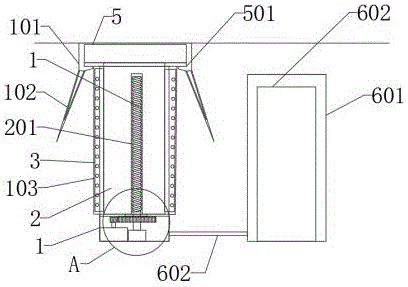
FIG. 1 is a schematic diagram of the overall structure of a novel lifting type electric vehicle charging pile;
FIG. 2 is an enlarged view of a lifting charging pile of the novel lifting type electric vehicle charging pile;
FIG. 3 is a sectional view of a novel lifting type wire rewinding device for an electric vehicle charging pile according to the utility model;
FIG. 4 is an enlarged view of the position A of the novel lifting type electric vehicle charging pile in FIG. 1
Fig. 5 is a partial upward view and an enlarged view of the novel lifting type electric vehicle charging pile.
In the figure: 1. installing a groove; 101. a sewage collecting groove; 102. a sewage discharge tank; 103. a limiting fixing groove; 2. lifting the charging pile; 201. thread concave holes; 3. a limiting connecting sheet; 301. a displacement pulley; 4. a charging groove; 401. a touch display; 5. a waterproof support upper cover; 501. a waterproof rubber pad; 6. a controller; 601. a master control power box; 602. a connecting wire; 7. a wire rewinding device; 701. rotating the grip; 702. a charging gun; 703. a power line; 8. a wire collecting disc; 801. a take-up motor; 802. supporting the connecting shaft; 803. connecting a bearing; 9. a power motor; 901. a driving connection gear; 902. a support base; 903. a connecting shaft; 904. a driven connecting gear; 905. a threaded rod.
Detailed Description
In order to make the technical means, the creation characteristics, the achievement purposes and the effects of the utility model easy to understand, the utility model is further described with the specific embodiments.
In the description of the present invention, it should be noted that the terms "upper", "lower", "inner", "outer", "front", "rear", "both ends", "one end", "the other end", and the like indicate orientations or positional relationships based on those shown in the drawings, and are only for convenience of description and simplicity of description, but do not indicate or imply that the referred device or element must have a specific orientation, be constructed in a specific orientation, and be operated, and thus, should not be construed as limiting the present invention. Furthermore, the terms "first" and "second" are used for descriptive purposes only and are not to be construed as indicating or implying relative importance. In the description of the present invention, it is to be noted that, unless otherwise explicitly specified or limited, the terms "mounted," "disposed," "connected," and the like are to be construed broadly, such as "connected," which may be fixedly connected, detachably connected, or integrally connected; can be mechanically or electrically connected; they may be connected directly or indirectly through intervening media, or they may be interconnected between two elements. The specific meanings of the above terms in the present invention can be understood in specific cases to those skilled in the art.
As shown in fig. 1-5, a novel lifting type electric vehicle charging pile comprises a mounting groove 1, a lifting charging pile 2 is movably mounted inside the mounting groove 1, limiting connecting sheets 3 are fixedly mounted on the outer surfaces of two sides of the lifting charging pile 2, a charging groove 4 is fixedly formed in the front surface of the lifting charging pile 2, a waterproof support upper cover 5 is fixedly mounted on the upper end surface of the lifting charging pile 2, a controller 6 is fixedly arranged on one side of the mounting groove 1, a power motor 9 is fixedly mounted at a position, close to the edge of the lower surface, inside the mounting groove 1, a wire rewinding device 7 is fixedly mounted inside the charging groove 4, and a wire collecting disc 8 is movably mounted inside the wire rewinding device 7;
a sewage collecting groove 101 is fixedly formed in the upper end face of the mounting groove 1, a sewage discharge groove 102 is fixedly formed in the sewage collecting groove 101, and limiting fixing grooves 103 are fixedly formed in two sides of the inside of the mounting groove 1; a threaded concave hole 201 is fixedly formed in the position, close to the center, of the lower end face of the lifting charging pile 2, and displacement pulleys 301 are movably mounted on the outer surfaces of the two sides of the limiting connecting piece 3; a touch display 401 is fixedly arranged in the charging groove 4, a waterproof rubber pad 501 is fixedly arranged on the lower surface of the waterproof support upper cover 5, a main control power box 601 is fixedly arranged in the controller 6, and the controller 6 is connected with the mounting groove 1 through a connecting wire 602; the charging gun 702 is movably mounted on the front surface of the wire collector 7, the power line 703 is fixedly mounted on the lower surface of the charging gun 702, the supporting connecting shaft 802 is fixedly mounted inside the wire collecting disc 8, the wire collecting motor 801 is fixedly mounted inside the wire collector 7, the output end of the wire collecting motor 801 is fixedly connected with one end of the supporting connecting shaft 802, the connecting bearing 803 is fixedly mounted on the front surface of the supporting connecting shaft 802, which is positioned inside the wire collector 7, and the rotating grip 701 is fixedly connected to the other end of the supporting connecting shaft 802; the output end of the power motor 9 is fixedly connected with a driving connecting gear 901, one side of the power motor 9 is fixedly provided with a supporting base 902, the upper end face of the supporting base 902 is movably provided with a connecting shaft 903, the positive surface of the connecting shaft 903 is fixedly provided with a driven connecting gear 904, the driving connecting gear 901 is matched with the driven connecting gear 904, and the upper end face of the connecting shaft 903 is fixedly provided with a threaded rod 905.
It should be noted that, the utility model is a novel lifting type charging pile for electric vehicles, when in use, firstly, the charging pile needs to be installed at a proper position, the power supply is switched on, when the electric vehicle needs to be charged, the power motor 9 is started to drive the driving connecting gear 901 to rotate, as the driving connecting gear 901 is matched with the driven connecting gear 904 to drive the driven connecting gear 904 to rotate, the driven connecting gear 904 drives the connecting shaft 903 to rotate, as the threaded rod 905 is movably installed in the threaded groove 201 formed on the lower surface of the lifting charging pile 2, the connecting shaft 903 rotates to drive the threaded rod 905 to rotate, so as to drive the lifting charging pile 2 to ascend and descend, a user can purchase electricity and the like through the touch display 401, after the charging is completed, the charging gun 702 needs to be placed on the surface of the wire collector 7, at the moment, the internal wire collecting motor 801 is started to drive the wire collecting disc 8 to rotate, thereby will scatter in the outside power cord 703 collects back to inside wire concentration dish 8, be blocked when outside power cord 703, can change and collect power cord 703 through the manual rotation wire concentration dish 8 of outside rotatory handle 701, the inside sewage that gets into mounting groove 1 of infiltration can be blocked to the sewage collection recess 101 that its set up, discharge from the sewage discharge tank 102 who sets up inside getting into the soil, prevent to fill the inside intake of electric pile, it is comparatively convenient and fast, and the lift fills electric pile 2 and is responsible for charging, main power conversion and control system can install inside underground, save the above-ground space.
The foregoing shows and describes the general principles and broad features of the present invention and advantages thereof. It will be understood by those skilled in the art that the present invention is not limited to the embodiments described above, which are described in the specification and illustrated only to illustrate the principle of the present invention, but that various changes and modifications may be made therein without departing from the spirit and scope of the present invention, which fall within the scope of the utility model as claimed. The scope of the utility model is defined by the appended claims and equivalents thereof.