CN216127306U - Take clout to retrieve cross cutting machine of function - Google Patents
Take clout to retrieve cross cutting machine of function Download PDFInfo
- Publication number
- CN216127306U CN216127306U CN202121869851.1U CN202121869851U CN216127306U CN 216127306 U CN216127306 U CN 216127306U CN 202121869851 U CN202121869851 U CN 202121869851U CN 216127306 U CN216127306 U CN 216127306U
- Authority
- CN
- China
- Prior art keywords
- pivot
- die
- support
- cutting machine
- motor
- Prior art date
- Legal status (The legal status is an assumption and is not a legal conclusion. Google has not performed a legal analysis and makes no representation as to the accuracy of the status listed.)
- Expired - Fee Related
Links
- 239000000463 material Substances 0.000 claims abstract description 21
- 238000004064 recycling Methods 0.000 claims abstract description 17
- 239000000835 fiber Substances 0.000 claims abstract description 12
- 230000005611 electricity Effects 0.000 claims description 4
- 230000008878 coupling Effects 0.000 claims description 2
- 238000010168 coupling process Methods 0.000 claims description 2
- 238000005859 coupling reaction Methods 0.000 claims description 2
- 238000011084 recovery Methods 0.000 abstract description 22
- 230000000694 effects Effects 0.000 description 9
- 229910000831 Steel Inorganic materials 0.000 description 3
- 239000010959 steel Substances 0.000 description 3
- 230000008901 benefit Effects 0.000 description 2
- DQXBYHZEEUGOBF-UHFFFAOYSA-N but-3-enoic acid;ethene Chemical compound C=C.OC(=O)CC=C DQXBYHZEEUGOBF-UHFFFAOYSA-N 0.000 description 2
- 239000005038 ethylene vinyl acetate Substances 0.000 description 2
- 238000000034 method Methods 0.000 description 2
- 229920001200 poly(ethylene-vinyl acetate) Polymers 0.000 description 2
- 239000000853 adhesive Substances 0.000 description 1
- 230000001070 adhesive effect Effects 0.000 description 1
- 239000002390 adhesive tape Substances 0.000 description 1
- 230000009286 beneficial effect Effects 0.000 description 1
- 230000008859 change Effects 0.000 description 1
- 230000007547 defect Effects 0.000 description 1
- 238000005516 engineering process Methods 0.000 description 1
- PCHJSUWPFVWCPO-UHFFFAOYSA-N gold Chemical compound [Au] PCHJSUWPFVWCPO-UHFFFAOYSA-N 0.000 description 1
- 239000010931 gold Substances 0.000 description 1
- 229910052737 gold Inorganic materials 0.000 description 1
- 238000007373 indentation Methods 0.000 description 1
- 238000009434 installation Methods 0.000 description 1
- 230000007246 mechanism Effects 0.000 description 1
- 239000007769 metal material Substances 0.000 description 1
- 230000004048 modification Effects 0.000 description 1
- 238000012986 modification Methods 0.000 description 1
- 230000002265 prevention Effects 0.000 description 1
- 230000008569 process Effects 0.000 description 1
Images

Landscapes
- Perforating, Stamping-Out Or Severing By Means Other Than Cutting (AREA)
Abstract
The utility model discloses a die cutting machine with a residual material recycling function, which comprises a bottom plate, a power unit and a die cutting unit, wherein the bottom plate is provided with a feeding hole; the bottom plate is provided with a mounting bracket; the power unit contains straight-teeth gear, first fiber container, second fiber container, first pivot and fixed bolster, the last surface mounting of bottom plate has straight support and fixed bolster, the surface rotation of fixed bolster installs first pivot and second pivot, install the second fiber container in the first pivot, install first fiber container in the second pivot, the straight-teeth gear is installed to the tip of second pivot, rotate on the straight support and install the third pivot, the plectane is installed to the one end of third pivot, the surface mounting of plectane has the fixed block. This take die-cutting machine of clout recovery function structure reliable degree is high, and stability is good, and cross cutting is efficient and effectual, and the security is high, and is effectual to the recovery of clout, prevents that the clout from wafting out, can satisfy people's requirement, provides help to people's work.
Description
Technical Field
The utility model relates to the technical field of die cutting machines, in particular to a die cutting machine with a residual material recycling function.
Background
The die-cutting machine is a mechanical device for die-cutting, indentation and gold stamping operation of partial non-metallic materials, non-setting adhesive, EVA (ethylene vinyl acetate), double faced adhesive tape, electronics, mobile phone rubber mats and the like, the die-cutting machine mainly adopts a template carved by a steel knife, a hardware mould, a steel wire or a steel plate, when the existing die-cutting machine works, the recovery of excess materials needs to be stopped, the die-cutting is not convenient to be carried out intermittently and continuously, and the die-cutting efficiency is greatly reduced.
Wherein application number 202020731935.8 provides among the modern technology a clout recovery mechanism that high-speed cross cutting machine was used, including the cross cutting platform, the middle part of cross cutting platform top surface is inlayed and is installed mounting plate, and the left side edge fixed mounting of mounting plate top surface has limit baffle, and limit baffle's right flank swing joint has the automatically controlled rotation cross cutting base for fixed connection with mounting plate's top surface, and the right side fixed mounting of automatically controlled rotation cross cutting base has the inclined plane recovery platform for fixed connection with mounting plate's top surface.
The die cutting machine is low in structure reliability, general in stability, low in die cutting efficiency and general in safety, and therefore the die cutting machine with the excess material recycling function is provided.
SUMMERY OF THE UTILITY MODEL
The utility model aims to overcome the existing defects and provides a die-cutting machine with a residual material recovery function, which has the advantages of high structural reliability, good stability, high die-cutting efficiency, good effect, high safety, good residual material recovery effect, residual material overflow prevention, capability of meeting the requirements of people, assistance for the work of people and capability of effectively solving the problems in the background art.
In order to achieve the purpose, the utility model provides the following technical scheme: a die-cutting machine with a residual material recycling function comprises a bottom plate, a power unit and a die-cutting unit;
a bottom plate: a mounting bracket is arranged on the bracket;
a power unit: the paper roll fixing device comprises a straight gear, a first paper roll, a second paper roll, a first rotating shaft and a fixing support, wherein the straight support and the fixing support are arranged on the upper surface of a base plate, the first rotating shaft and a second rotating shaft are arranged on the outer surface of the fixing support in a rotating mode, the second paper roll is arranged on the first rotating shaft, the first paper roll is arranged on the second rotating shaft, the straight gear is arranged at the end of the second rotating shaft, a third rotating shaft is arranged on the straight support in a rotating mode, a circular plate is arranged at one end of the third rotating shaft, a fixing block is arranged on the outer surface of the circular plate, a groove is formed in the fixing block, and the groove of the fixing block is connected with the straight gear in a meshing mode;
a die cutting unit: which is mounted on the side of the mounting bracket.
Further, the power unit still contains end cover and first fixture block, the surface mounting of first pivot has first fixture block, first draw-in groove has been seted up to the inside of second fiber container, first fixture block and first draw-in groove joint, the end cover has still been cup jointed in the first pivot. When the paper on the second paper tube is used up, the end sleeve, the first clamping block and the first clamping groove can be detached, and the second paper tube is replaced.
Further, the power unit still contains motor support and motor, the side fixed mounting of straight support has motor support, the last motor that installs of motor support, the output shaft of motor has the other end of third pivot through the coupling joint, the output of external control ware is connected to the input electricity of motor. Through external controller control motor, motor work drives the third pivot and rotates, utilizes motor to promote the effect and the efficiency of intermittent type nature cross cutting, reduces intensity of labour to reduce workman injured potential danger.
Further, the cross cutting unit contains pneumatic cylinder, pneumatic cylinder support, die-cutting rule and cross cutting shim, the surface mounting of installing support has pneumatic cylinder support and working plate, install the pneumatic cylinder on the pneumatic cylinder support, the die-cutting rule is installed to the tip of pneumatic cylinder, the last surface mounting of working plate has the cross cutting shim, the output of external control ware is connected to the input electricity of pneumatic cylinder. The hydraulic cylinder is controlled to work through the external controller, a piston rod of the hydraulic cylinder stretches out to drive the die-cutting rule to move downwards, the die-cutting rule is matched with the die-cutting knife pad, die cutting is conducted on paper, and the die-cutting effect is good.
Further, still including retrieving the unit, it contains slider, spacing post, end cap and collection box to retrieve the unit, the spout has been seted up to the side of working plate, the side-mounting of collection box has the slider, slider and spout sliding connection, spacing hole has all been seted up on working plate and the slider, spacing post and spacing hole sliding connection, the end cap is installed to the tip of spacing post. The sliding block is used for installing the recovery box on the sliding groove through the limiting column and the limiting hole, paper after die cutting moves forwards, and the excess material is driven to move forwards, so that the excess material is sent into the recovery box, the structure reliability is high, and the stability is strong.
Further, the recycling unit further comprises a second clamping block and a baffle, a second clamping groove is formed in the upper surface of the recycling box, the second clamping block is mounted on the lower surface of the baffle, and the second clamping block is connected with the second clamping groove in a buckled mode. The baffle is the triangle-shaped form, prevents that the front end from having sharp-pointed part to cause the damage to paper, with the baffle joint on the collection box, the convenience is to the recovery of clout, prevents that the clout from wafting out.
Compared with the prior art, the utility model has the beneficial effects that: this take clout to retrieve cross cutting machine of function has following benefit:
1. this take clout to retrieve cross cutting machine of function has power pack, carries out intermittent type nature cross cutting through the paper on power pack's the second fiber container, then rolls up on the first fiber container again, improves the efficiency of cross cutting, can change the second fiber container, utilizes the motor to promote effect and the efficiency of intermittent type nature cross cutting, reduces intensity of labour to reduce workman injured potential danger.
2. This take clout to retrieve cross cutting machine of function has the recovery unit, and the paper after the cross cutting moves forward, drives the clout and moves forward to in sending into the collection box with the clout, the reliable degree of structure is high, and stability is strong, with the baffle joint on the collection box, the convenient recovery to the clout prevents that the clout from wafting.
3. This take die-cutting machine of clout recovery function structure reliable degree is high, and stability is good, and cross cutting is efficient and effectual, and the security is high, and is effectual to the recovery of clout, prevents that the clout from wafting out, can satisfy people's requirement, provides help to people's work.
Drawings
FIG. 1 is a schematic structural view of the present invention;
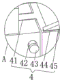
fig. 2 is a schematic view of the locally enlarged novel structure at a position of the present invention.
In the figure: the automatic cutting machine comprises a base plate 1, a power unit 2, a motor support 21, a motor 22, a spur gear 23, a first paper tube 24, a second paper tube 25, an end sleeve 26, a first fixture block 27, a first rotating shaft 28, a fixed support 29, a die cutting unit 3, a hydraulic cylinder 31, a hydraulic cylinder support 32, a die cutting knife 33, a die cutting knife pad 34, a recovery unit 4, a sliding block 41, a limiting column 42, an end cap 43, a second fixture block 44, a baffle 45, a recovery box 46, a working plate 5, an installation support 6, a circular plate 7, a fixed block 8 and a straight support 9.
Detailed Description
The technical solutions in the embodiments of the present invention will be clearly and completely described below with reference to the drawings in the embodiments of the present invention, and it is obvious that the described embodiments are only a part of the embodiments of the present invention, and not all of the embodiments. All other embodiments, which can be derived by a person skilled in the art from the embodiments given herein without making any creative effort, shall fall within the protection scope of the present invention.
Referring to fig. 1-2, the present embodiment provides a technical solution: a die-cutting machine with a residual material recycling function comprises a bottom plate 1, a power unit 2 and a die-cutting unit 3;
bottom plate 1: a mounting bracket 6 is arranged on the bracket; still including retrieving unit 4, retrieving unit 4 and containing slider 41, spacing post 42, end cap 43 and collection box 46, the spout has been seted up to the side of working plate 5, and the side-mounting of collection box 46 has slider 41, and slider 41 and spout sliding connection have all seted up spacing hole on working plate 5 and the slider 41, spacing post 42 and spacing hole sliding connection, and end cap 43 is installed to the tip of spacing post 42. The sliding block 41 is used for installing the recovery box 46 on the sliding chute through the limiting column 42 and the limiting hole, and when the paper subjected to die cutting moves forwards, the excess material is driven to move forwards, so that the excess material is sent into the recovery box 46, and the structure is high in reliability and strong in stability. The recycling unit 4 further comprises a second clamping block 44 and a baffle 45, a second clamping groove is formed in the upper surface of the recycling box 46, the second clamping block 44 is installed on the lower surface of the baffle 45, and the second clamping block 44 is connected with the second clamping groove in a clamping mode. Baffle 45 is the triangle-shaped form, prevents that the front end from having the sharp-pointed part to cause the damage to paper, with baffle 45 joint on collection box 46, the convenient recovery to the clout prevents that the clout from wafting out.
The power unit 2: the paper roll fixing device comprises a straight gear 23, a first paper tube 24, a second paper tube 25, a first rotating shaft 28 and a fixing support 29, a straight support 9 and a fixing support 26 are mounted on the upper surface of a base plate 1, a first rotating shaft 28 and a second rotating shaft are rotatably mounted on the outer surface of the fixing support 26, the second paper tube 25 is mounted on the first rotating shaft 28, the first paper tube 24 is mounted on the second rotating shaft, the straight gear 23 is mounted at the end part of the second rotating shaft, a third rotating shaft is rotatably mounted on the straight support 9, a circular plate 7 is mounted at one end of the third rotating shaft, a fixing block 8 is mounted on the outer surface of the circular plate 7, a groove is formed in the fixing block 8, and the groove of the fixing block 8 is meshed with the straight gear 23; the circular plate 7 is driven to rotate by rotating the first rotating shaft 28, the circular plate 7 rotates to drive the fixing block 8 to rotate, the fixing block 8 rotates to drive the straight gear 23 to rotate, the straight gear 23 rotates to drive the second rotating shaft to rotate, the second rotating shaft rotates to drive the first paper tube 24 to rotate, the first paper tube 24 rotates to drive the second paper tube 25 to rotate, paper on the second paper tube 25 is subjected to intermittent die cutting, and then the paper is rolled onto the first paper tube 24, so that the die cutting efficiency is improved. The power unit 2 further comprises an end sleeve 26 and a first clamping block 27, the first clamping block 27 is mounted on the outer surface of the first rotating shaft 28, a first clamping groove is formed in the second paper tube 25, the first clamping block 27 is clamped with the first clamping groove, and the end sleeve 26 is further sleeved on the first rotating shaft 28. When the paper on the second paper tube 25 is used up, the end sleeve 26, the clamped first clamping block 27 and the clamped first clamping groove can be detached, and a new second paper tube 25 can be replaced. The power unit 2 further comprises a motor support 21 and a motor 22, the side face of the straight support 9 is fixedly provided with the motor support 21, the motor 22 is arranged on the motor support 21, an output shaft of the motor 22 is connected with the other end of the third rotating shaft through a coupler, and an input end of the motor 22 is electrically connected with an output end of an external controller. Through external control ware control motor 22, motor 22 work drives the third pivot and rotates, utilizes motor 22 to promote the effect and the efficiency of intermittent type nature cross cutting, reduces intensity of labour to reduce workman injured's potential danger.
The die cutting unit 3: which is mounted on the side of the mounting bracket 6. The die cutting unit 3 comprises a hydraulic cylinder 31, a hydraulic cylinder support 32, a die cutting knife 33 and a die cutting knife pad 34, the hydraulic cylinder support 32 and the working plate 5 are mounted on the outer surface of the mounting support 6, the hydraulic cylinder 31 is mounted on the hydraulic cylinder support 32, the die cutting knife 33 is mounted at the end part of the hydraulic cylinder 31, the die cutting knife pad 34 is mounted on the upper surface of the working plate 5, and the input end of the hydraulic cylinder 31 is electrically connected with the output end of an external controller. The hydraulic cylinder 31 is controlled to work through an external controller, a piston rod of the hydraulic cylinder 31 extends out to drive the die-cutting rule 33 to move downwards, the die-cutting rule 33 is matched with the die-cutting knife pad 34 to perform die cutting on paper, and the die-cutting effect is good.
The working principle of the die-cutting machine with the excess material recycling function provided by the utility model is as follows: through external control ware control motor 22, motor 22 work drives the third pivot and rotates, utilizes motor 22 to promote the effect and the efficiency of intermittent type nature cross cutting, reduces intensity of labour to reduce workman injured's potential danger. The third rotating shaft is rotated to drive the circular plate 7 to rotate, the circular plate 7 is rotated to drive the fixing block 8 to rotate, the fixing block 8 is rotated to drive the straight gear 23 to rotate, the straight gear 23 is rotated to drive the second rotating shaft to rotate, the second rotating shaft is rotated to drive the first paper tube 24 to rotate, the first paper tube 24 is rotated to drive the second paper tube 25 to rotate, intermittent die cutting is performed on paper on the second paper tube 25, and then the paper is rolled onto the first paper tube 24, so that the die cutting efficiency is improved. When the paper on the second paper tube 25 is used up, the end sleeve 26, the clamped first clamping block 27 and the clamped first clamping groove can be detached, and a new second paper tube 25 can be replaced. The hydraulic cylinder 31 is controlled to work through an external controller, a piston rod of the hydraulic cylinder 31 extends out to drive the die-cutting rule 33 to move downwards, the die-cutting rule 33 is matched with the die-cutting knife pad 34 to perform die cutting on paper, and the die-cutting effect is good. The sliding block 41 is used for installing the recovery box 46 on the sliding chute through the limiting column 42 and the limiting hole, and when the paper subjected to die cutting moves forwards, the excess material is driven to move forwards, so that the excess material is sent into the recovery box 46, and the structure is high in reliability and strong in stability. Baffle 45 is the triangle-shaped form, prevents that the front end from having the sharp-pointed part to cause the damage to paper, with baffle 45 joint on collection box 46, the convenient recovery to the clout prevents that the clout from wafting out.
It should be noted that in this embodiment, the core chip of the external controller is an STC single chip microcomputer, the specific model is STC15W204S, the hydraulic cylinder 31 and the motor 22 can be freely configured according to the actual application scenario, and the motor 22 can be a JE series single-phase servo motor manufactured by mitsubishi motors (china) ltd. The external controller controls the operation of the hydraulic cylinder 31 and the motor 22 by a method commonly used in the art.
The above description is only an embodiment of the present invention, and not intended to limit the scope of the present invention, and all modifications of equivalent structures and equivalent processes, which are made by using the contents of the present specification and the accompanying drawings, or directly or indirectly applied to other related technical fields, are included in the scope of the present invention.
Claims (6)
1. The utility model provides a take clout to retrieve cross cutting machine of function which characterized in that: comprises a bottom plate (1), a power unit (2) and a die cutting unit (3);
base plate (1): a mounting bracket (6) is arranged on the bracket;
power unit (2): contain straight-teeth gear (23), first fiber container (24), second fiber container (25), first pivot (28) and fixed bolster (29), the last surface mounting of bottom plate (1) has straight support (9) and fixed bolster (29), the surface rotation of fixed bolster (29) installs first pivot (28) and second pivot, install second fiber container (25) on first pivot (28), install first fiber container (24) in the second pivot, straight-teeth gear (23) are installed to the tip of second pivot, rotate on straight support (9) and install the third pivot, plectane (7) are installed to the one end of third pivot, the surface mounting of plectane (7) has fixed block (8), the recess has been seted up on fixed block (8), the recess and the straight-teeth gear (23) meshing of fixed block (8) are connected;
die cutting unit (3): which is mounted on the side of the mounting bracket (6).
2. The die cutting machine with the excess material recycling function according to claim 1, characterized in that: the power unit (2) further comprises an end sleeve (26) and a first clamping block (27), the outer surface of the first rotating shaft (28) is provided with the first clamping block (27), the inside of the second paper tube (25) is provided with a first clamping groove, the first clamping block (27) is connected with the first clamping groove in a clamped mode, and the end sleeve (26) is further sleeved on the first rotating shaft (28).
3. The die cutting machine with the excess material recycling function according to claim 2, characterized in that: power unit (2) still contain motor support (21) and motor (22), the side fixed mounting of straight support (9) has motor support (21), install motor (22) on motor support (21), the output shaft of motor (22) has the other end of third pivot through the coupling joint, the output of external control ware is connected to the input electricity of motor (22).
4. The die cutting machine with the excess material recycling function according to claim 1, characterized in that: die cutting unit (3) contain pneumatic cylinder (31), pneumatic cylinder support (32), die-cutting rule (33) and cross cutting shim (34), the surface mounting of installing support (6) has pneumatic cylinder support (32) and working plate (5), install pneumatic cylinder (31) on pneumatic cylinder support (32), die-cutting rule (33) are installed to the tip of pneumatic cylinder (31), the last surface mounting of working plate (5) has cross cutting shim (34), the output of external control ware is connected to the input electricity of pneumatic cylinder (31).
5. The die cutting machine with the excess material recycling function according to claim 4, characterized in that: still including retrieving unit (4), retrieve unit (4) and contain slider (41), spacing post (42), end cap (43) and collection box (46), the spout has been seted up to the side of working plate (5), the side-mounting of collection box (46) has slider (41), slider (41) and spout sliding connection, spacing hole has all been seted up on working plate (5) and slider (41), spacing post (42) and spacing hole sliding connection, end cap (43) are installed to the tip of spacing post (42).
6. The die cutting machine with the excess material recycling function according to claim 5, characterized in that: the recycling unit (4) further comprises a second clamping block (44) and a baffle (45), a second clamping groove is formed in the upper surface of the recycling box (46), the second clamping block (44) is mounted on the lower surface of the baffle (45), and the second clamping block (44) is connected with the second clamping groove in a buckled mode.
Priority Applications (1)
| Application Number | Priority Date | Filing Date | Title |
|---|---|---|---|
| CN202121869851.1U CN216127306U (en) | 2021-08-11 | 2021-08-11 | Take clout to retrieve cross cutting machine of function |
Applications Claiming Priority (1)
| Application Number | Priority Date | Filing Date | Title |
|---|---|---|---|
| CN202121869851.1U CN216127306U (en) | 2021-08-11 | 2021-08-11 | Take clout to retrieve cross cutting machine of function |
Publications (1)
| Publication Number | Publication Date |
|---|---|
| CN216127306U true CN216127306U (en) | 2022-03-25 |
Family
ID=80769582
Family Applications (1)
| Application Number | Title | Priority Date | Filing Date |
|---|---|---|---|
| CN202121869851.1U Expired - Fee Related CN216127306U (en) | 2021-08-11 | 2021-08-11 | Take clout to retrieve cross cutting machine of function |
Country Status (1)
| Country | Link |
|---|---|
| CN (1) | CN216127306U (en) |
-
2021
- 2021-08-11 CN CN202121869851.1U patent/CN216127306U/en not_active Expired - Fee Related
Similar Documents
| Publication | Publication Date | Title |
|---|---|---|
| CN210754499U (en) | Door frame forming machine | |
| CN211219609U (en) | Motor shaft combined machining device | |
| CN208814888U (en) | A kind of glass-cutting sliver line | |
| CN216686270U (en) | Be used for stainless steel processing guider | |
| CN211566038U (en) | Paper tube slitting device | |
| CN214782809U (en) | Tailoring is with cutting curved platform that cuts | |
| CN212222794U (en) | Cutting device is used in glass board processing | |
| CN213197760U (en) | Cutting device of protection film | |
| CN220886429U (en) | Punching and cutting device for photovoltaic tin-plated solder strip | |
| CN212126928U (en) | Template cutting machine with garbage collection mechanism | |
| CN214446921U (en) | A glue cutting machine with fixed distance cutting function | |
| CN223921303U (en) | A glass cutting platform | |
| CN213763847U (en) | Thin film capacitor pin pushing device | |
| CN221437477U (en) | Full-automatic card gilding press | |
| CN218695027U (en) | Laser cutting device | |
| CN220992675U (en) | Quantitative cutting mechanism for soldering tin wire | |
| CN220837661U (en) | Anti-blocking device of wire bending machine | |
| CN218693394U (en) | A many rounds of straightener for steel fibre production | |
| CN219518980U (en) | High-efficient garrulous pearl machine | |
| CN216731945U (en) | Cutting device for cake paper | |
| CN212885052U (en) | Rotor excircle processing machine | |
| CN218361523U (en) | Processing device of gas meter shell | |
| CN217802333U (en) | Aerated concrete blank cutting machine capable of longitudinally cutting and milling grooves | |
| CN221454042U (en) | Novel aluminium product perforator | |
| CN216263840U (en) | Full-automatic saw cutting device for tower crane standard knot main chord member profile |
Legal Events
| Date | Code | Title | Description |
|---|---|---|---|
| GR01 | Patent grant | ||
| GR01 | Patent grant | ||
| CF01 | Termination of patent right due to non-payment of annual fee | ||
| CF01 | Termination of patent right due to non-payment of annual fee |
Granted publication date: 20220325 |