CN216119586U - High-tensile anti-torsion wind power cable - Google Patents
High-tensile anti-torsion wind power cable Download PDFInfo
- Publication number
- CN216119586U CN216119586U CN202121974756.8U CN202121974756U CN216119586U CN 216119586 U CN216119586 U CN 216119586U CN 202121974756 U CN202121974756 U CN 202121974756U CN 216119586 U CN216119586 U CN 216119586U
- Authority
- CN
- China
- Prior art keywords
- cable core
- conductor
- tensile
- core
- cable
- Prior art date
- Legal status (The legal status is an assumption and is not a legal conclusion. Google has not performed a legal analysis and makes no representation as to the accuracy of the status listed.)
- Active
Links
- 239000004020 conductor Substances 0.000 claims abstract description 64
- 239000010410 layer Substances 0.000 claims abstract description 39
- 238000004804 winding Methods 0.000 claims abstract description 30
- 239000003063 flame retardant Substances 0.000 claims abstract description 14
- RNFJDJUURJAICM-UHFFFAOYSA-N 2,2,4,4,6,6-hexaphenoxy-1,3,5-triaza-2$l^{5},4$l^{5},6$l^{5}-triphosphacyclohexa-1,3,5-triene Chemical compound N=1P(OC=2C=CC=CC=2)(OC=2C=CC=CC=2)=NP(OC=2C=CC=CC=2)(OC=2C=CC=CC=2)=NP=1(OC=1C=CC=CC=1)OC1=CC=CC=C1 RNFJDJUURJAICM-UHFFFAOYSA-N 0.000 claims abstract description 13
- 239000011241 protective layer Substances 0.000 claims abstract description 10
- 239000004718 silane crosslinked polyethylene Substances 0.000 claims abstract description 7
- 229920006231 aramid fiber Polymers 0.000 claims abstract description 5
- 239000000919 ceramic Substances 0.000 claims abstract description 5
- 239000002131 composite material Substances 0.000 claims abstract description 5
- 229920002379 silicone rubber Polymers 0.000 claims abstract description 5
- 150000001875 compounds Chemical class 0.000 claims abstract description 4
- RYGMFSIKBFXOCR-UHFFFAOYSA-N Copper Chemical compound [Cu] RYGMFSIKBFXOCR-UHFFFAOYSA-N 0.000 claims description 6
- 229910052802 copper Inorganic materials 0.000 claims description 6
- 239000010949 copper Substances 0.000 claims description 6
- 238000007765 extrusion coating Methods 0.000 claims description 4
- 239000011247 coating layer Substances 0.000 claims description 2
- 230000005611 electricity Effects 0.000 claims 1
- 238000001125 extrusion Methods 0.000 abstract description 2
- 238000005452 bending Methods 0.000 description 5
- 238000010248 power generation Methods 0.000 description 5
- 239000000463 material Substances 0.000 description 3
- 238000000034 method Methods 0.000 description 3
- 238000010292 electrical insulation Methods 0.000 description 2
- 238000004519 manufacturing process Methods 0.000 description 2
- 241001391944 Commicarpus scandens Species 0.000 description 1
- 239000002253 acid Substances 0.000 description 1
- 230000032683 aging Effects 0.000 description 1
- 239000003513 alkali Substances 0.000 description 1
- 239000004760 aramid Substances 0.000 description 1
- 230000005540 biological transmission Effects 0.000 description 1
- 210000004204 blood vessel Anatomy 0.000 description 1
- 238000006243 chemical reaction Methods 0.000 description 1
- 230000007797 corrosion Effects 0.000 description 1
- 238000005260 corrosion Methods 0.000 description 1
- 229920003020 cross-linked polyethylene Polymers 0.000 description 1
- 239000004703 cross-linked polyethylene Substances 0.000 description 1
- 230000007547 defect Effects 0.000 description 1
- 230000005672 electromagnetic field Effects 0.000 description 1
- 230000009970 fire resistant effect Effects 0.000 description 1
- 239000011810 insulating material Substances 0.000 description 1
- 238000012986 modification Methods 0.000 description 1
- 230000004048 modification Effects 0.000 description 1
- 210000005036 nerve Anatomy 0.000 description 1
- 229920000642 polymer Polymers 0.000 description 1
Images
Classifications
-
- Y—GENERAL TAGGING OF NEW TECHNOLOGICAL DEVELOPMENTS; GENERAL TAGGING OF CROSS-SECTIONAL TECHNOLOGIES SPANNING OVER SEVERAL SECTIONS OF THE IPC; TECHNICAL SUBJECTS COVERED BY FORMER USPC CROSS-REFERENCE ART COLLECTIONS [XRACs] AND DIGESTS
- Y02—TECHNOLOGIES OR APPLICATIONS FOR MITIGATION OR ADAPTATION AGAINST CLIMATE CHANGE
- Y02A—TECHNOLOGIES FOR ADAPTATION TO CLIMATE CHANGE
- Y02A30/00—Adapting or protecting infrastructure or their operation
- Y02A30/14—Extreme weather resilient electric power supply systems, e.g. strengthening power lines or underground power cables
Landscapes
- Ropes Or Cables (AREA)
Abstract
The utility model discloses a high-tensile anti-torsion wind power cable, wherein three strands of a cable core are positioned at the periphery of a cable core tensile rope, each strand comprises a cable core tensile rope and a cable core conductor bundle twisted at the periphery of the cable core tensile rope, and the ratio D/D of the outer diameter D of the cable core tensile rope to the outer diameter D of the cable core conductor bundle is = 1.5-1.8; the pitch diameter ratio of the core conductor bundle is 16-18, and the pitch diameter ratio of the folded yarn is 8-10; the compound yarn is coated with an insulating layer, and a conductor sparse winding layer, a flame-retardant winding layer and an outer protective layer are sequentially coated outside the cable core from inside to outside; the sum of the conductor cross sections of the conductor sparse winding layers is 65% -75% of the sum of the conductor cross sections of the stranded wires. The winding anti-knot rope and the cable core anti-tensile rope are aramid fiber ropes. The insulating layer and the outer protective layer are silane crosslinked polyethylene extrusion layers, and the flame-retardant insulating layer is formed by wrapping a ceramic silicon rubber composite tape. The wind power cable is good in flexibility and high in tensile dragging strength.
Description
Technical Field
The utility model relates to the technical field of wind generating sets, in particular to an electric energy transmission cable for a wind driven generator.
Background
Wind power generation systems are a combination of mechanical, electrical and their control devices that convert wind energy into electrical energy. The wind power generation system is characterized in that all devices in the wind power generation system are connected by corresponding cables, an energy conversion device serving as a core of wind power generation, namely a wind generating set, is not separated from the cables to transmit and convert energy, and in the whole wind power generation system, the cables are blood vessels and nerves of the whole system and play an irreplaceable and important role.
The operation environment of a wind generating set is severe mostly, the wind blade of the wind generating set swings irregularly according to the wind direction, a cable is frequently and randomly twisted, swung and pulled along with the direction of the wind blade, the twisting speed and the angle of the cable are uncertain, the cable is vibrated and twisted in a wind power tower, the formed shaking amplitude and the formed pulling force are uncertain, and the cable is complex in the arrangement paths of the wind generating set and the tower, so that an insulated wire core is easily formed to be displaced, a bulge is formed, and the insulated wire core is subjected to fatigue fracture; particularly, the existing wind power cable adopts a 3 + 1 cable core structure, wherein a grounding core wire with a relatively small wire diameter is easy to break and damage; with the continuous increase of wind power towers, cables for transmitting electric energy are correspondingly longer, the functions of the cables in traction and twisting are more obvious, and the conventional wind power cables cannot meet the comprehensive performance requirements of high torsion resistance, tensile strength, enough mechanical strength and the like.
SUMMERY OF THE UTILITY MODEL
Aiming at the defects in the prior art, the utility model aims to provide the high-tensile-strength anti-torsion wind power cable which is good in flexibility, stable in cable core structure and high in tensile-strength dragging strength.
In order to solve the technical problem, the high-tensile anti-torsion wind power cable comprises a cable core, wherein the cable core is composed of three strands and a cable core tensile rope, the three strands are located on the periphery of the cable core tensile rope, each strand comprises a cable core tensile rope and a cable core conductor bundle twisted on the periphery of the cable core tensile rope, and the ratio D/D of the outer diameter D of the cable core tensile rope to the outer diameter D of the cable core conductor bundle is = 1.5-1.8; the pitch-diameter ratio of the core conductor bundle is 16-18, and the pitch-diameter ratio of the folded yarn is 8-10; the compound yarn is coated with an insulating layer, and a conductor sparse winding layer, a flame-retardant winding layer and an outer protective layer are sequentially coated outside the cable core from inside to outside; the sum of the conductor sectional areas of the conductor sparse winding layer is 65% -75% of the sum of the conductor sectional areas of the stranded wires.
In the structure, the cable core is composed of three strands, a conductor sparse winding layer is coated outside the cable core, the sum of the conductor sectional areas of the conductor sparse winding layer is 65% -75% of the sum of the conductor sectional areas of the strands, and the conductor sparse winding layer not only plays a role of a cable ground wire, but also has a cable shielding function and avoids leakage interference of an electromagnetic field of the cable; the sparse winding ground wire structure greatly increases the bending radius of the ground wire and has better bending resistance and twisting resistance. And because the core conductor bundle is stranded at the periphery of the core tensile rope, and the outer diameter of the core tensile rope is larger than that of the core conductor bundle, the structure greatly enhances the mechanical properties of tensile resistance, twisting resistance and the like of the strand, and increases the bending radius of the core conductor bundle positioned at the periphery of the core tensile rope, thereby effectively improving the flexibility and the bending resistance of the cable. The core conductor and the strand adopt reasonable pitch-diameter ratio, so that the tension balance of each monofilament conductor in the strand bundle can be realized, the fracture of the monofilament conductor in the manufacturing and using processes can be avoided or reduced, the whole strand conductor has enough good mechanical properties of stretch resistance, bending resistance and extrusion resistance, the stranding tightness between the monofilaments and the strand bundle can be effectively ensured, the strand loosening can be prevented, the excessive embedding between the adjacent monofilaments can be avoided, and the twisting flexibility of the cable can be ensured. The cable core is coated with the flame-retardant wrapping layer and the outer protective layer, so that the flame-retardant and high-temperature-resistant protection performance of the cable is enhanced.
In a preferred embodiment of the utility model, the core conductor bundle is formed by stranding oxygen-free copper wires with the diameter of 0.15 mm-0.20 mm; the conductor sparse winding layer is formed by winding anaerobic copper wires with the diameter of 0.15 mm-0.20 mm.
In a preferred embodiment of the utility model, the core winding anti-kink rope and the core cable anti-tensile rope are aramid fiber ropes. Not only light weight, but also high temperature resistance, acid and alkali resistance.
In a preferred embodiment of the utility model, the insulating layer is a silane crosslinked polyethylene extrusion coating layer, and the flame-retardant insulating layer is formed by wrapping a ceramic silicon rubber composite tape; the outer protective layer is a silane cross-linked polyethylene extrusion coating. Has good mechanical property and electrical insulation property, and is simple and convenient to process.
Drawings
The utility model further discloses a high-tensile anti-torsion wind power cable, which is described in the following by combining the attached drawings and the detailed description.
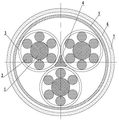
FIG. 1 is a schematic cross-sectional structure view of an embodiment of the high-tensile anti-torsion wind power cable according to the present invention;
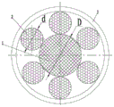
fig. 2 is an enlarged schematic view of a strand unit in the embodiment shown in fig. 1.
In the figure, 1-core tensile rope, 2-core conductor bundle, 3-insulating layer, 4-core tensile rope, 5-conductor sparse winding layer, 6-flame retardant winding layer and 7-outer protective layer.
Detailed Description
The high-tensile-strength anti-torsion wind power cable shown in figure 1 has the advantages that the cable core of the wind power cable is composed of three strands and a cable core tensile rope 4, the cable core tensile rope 4 is pulled at the central position of the cable core, the three strands are twisted at the periphery of the cable core tensile rope 4, and the cable core tensile rope 4 is a rope made of aramid fibers and has the advantages of being high in strength, fireproof, flame-retardant and high-temperature-resistant. The cable core is sequentially coated with a conductor sparse winding layer 5, a flame-retardant winding layer 6 and an outer protective layer 7 from inside to outside. The conductor sparse winding layer 5 is formed by winding a plurality of oxygen-free copper wires with the diameter of 0.20mm outside the cable core; the flame-retardant wrapping layer 6 is formed by wrapping a ceramic silicon rubber composite tape, and the ceramic silicon rubber composite tape has the advantages of excellent flame-retardant property, high flame-retardant and fire-resistant grade, excellent mechanical property and excellent electrical insulation property; the cost can be greatly reduced, and the production efficiency is improved; the outer protective layer 7 is formed by extruding silane cross-linked polyethylene material, has the characteristics of corrosion resistance, ageing resistance and flame retardance, and is simple and convenient to process.
As shown in fig. 2, the strand in the cable core includes a core tensile cord 1 located at the center of the strand, and a core conductor bundle 2 stranded on the outer periphery of the core tensile cord 1. The core tensile rope 1 is an aramid fiber thin rope, the core conductor bundle 2 is formed by stranding oxygen-free copper wires with the diameter of 0.15mm, the diameter D =1.68mm of the core tensile rope 1, the diameter D =0.98mm of the core conductor bundle 2, the stranding pitch of the core conductor bundle 2 is 15.68mm, and the pitch-diameter ratio of the core conductor bundle 2 is 16. The diameter of a strand consisting of the six core conductor bundles 2 and the core tensile rope 1 is 3.64mm, the stranding pitch of the strand is 32.76mm, the pitch-diameter ratio of the strand is 9, and the stranding directions of the core conductor bundles 2 and the strand are both right. The number of the conductor sparse winding layers 5 is determined by the product of the sectional areas of the conductor sparse winding layers and the product of the sectional areas of the conductors of the six core conductor bundles 2 of the stranded wires, namely the sum of the sectional areas of the conductors of the conductor sparse winding layers 5 is 65% -75% of the sum of the sectional areas of the conductors of the core conductor bundles forming the stranded wires. The compound yarn is coated with an insulating layer 3, and the insulating layer 3 is formed by extruding silane cross-linked polyethylene materials.
The foregoing description shows a preferred embodiment of the present invention, but the present invention is not limited thereto, and various modifications and changes can be made without departing from the basic concept of the present invention. If the conductor bundle 2 is not limited to six, the number of the conductor bundles can be determined according to the magnitude of the electric energy current; the stranding directions of the core conductor bundle 2 and the strand are both left direction, or one is left direction and the other is right direction, and the conductor diameters of the core conductor bundle 2 and the conductor sparse winding layer 5 are controlled between 0.15mm and 0.20 mm; the ratio D/D of the outer diameter D of the core tensile rope to the outer diameter D of the core conductor bundle is preferably in the range of 1.5-1.8; the pitch-diameter ratio of the core conductor bundle is preferably 16-18; the pitch-diameter ratio of the strands is preferably 8-10, and the extruded material of the insulating layer can also be other polymer insulating materials such as crosslinked polyethylene and the like. And the like, all of which are intended to fall within the scope of the present invention.
Claims (4)
1. The utility model provides a antitorque wind-powered electricity generation cable of high tensile, includes the cable core, its characterized in that: the cable core is composed of three strands and a cable core tensile rope (4), the three strands are located on the periphery of the cable core tensile rope (4), each strand comprises a cable core tensile rope (1) and a cable core conductor bundle (2) which is stranded on the periphery of the cable core tensile rope (1), and the ratio D/D of the outer diameter D of the cable core tensile rope (1) to the outer diameter D of the cable core conductor bundle (2) is = 1.5-1.8; the pitch-diameter ratio of the core conductor bundle (2) is 16-18, and the pitch-diameter ratio of the folded yarn is 8-10; the compound yarn is coated with an insulating layer (3), and a conductor sparse winding layer (5), a flame-retardant winding layer (6) and an outer protective layer (7) are sequentially coated outside the cable core from inside to outside; the sum of the conductor sectional areas of the conductor sparse winding layer (5) is 65% -75% of the sum of the conductor sectional areas of the stranded wires.
2. The high-tensile anti-torsion wind power cable according to claim 1, wherein: the core conductor bundle (2) is formed by stranding anaerobic copper wires with the diameter of 0.15 mm-0.20 mm; the conductor sparse winding layer (5) is formed by winding anaerobic copper wires with the diameter of 0.15 mm-0.20 mm.
3. The high-tensile anti-torsion wind power cable according to claim 1, wherein: the winding core anti-knotting rope (1) and the cable core anti-stretching rope (4) are aramid fiber ropes.
4. The high-tensile anti-torsion wind power cable according to claim 1, wherein: the insulating layer (3) is a silane crosslinked polyethylene extrusion coating, and the flame-retardant insulating layer (6) is formed by wrapping a ceramic silicon rubber composite tape; the outer protective layer (7) is a silane crosslinked polyethylene extrusion coating layer.
Priority Applications (1)
| Application Number | Priority Date | Filing Date | Title |
|---|---|---|---|
| CN202121974756.8U CN216119586U (en) | 2021-08-23 | 2021-08-23 | High-tensile anti-torsion wind power cable |
Applications Claiming Priority (1)
| Application Number | Priority Date | Filing Date | Title |
|---|---|---|---|
| CN202121974756.8U CN216119586U (en) | 2021-08-23 | 2021-08-23 | High-tensile anti-torsion wind power cable |
Publications (1)
| Publication Number | Publication Date |
|---|---|
| CN216119586U true CN216119586U (en) | 2022-03-22 |
Family
ID=80727718
Family Applications (1)
| Application Number | Title | Priority Date | Filing Date |
|---|---|---|---|
| CN202121974756.8U Active CN216119586U (en) | 2021-08-23 | 2021-08-23 | High-tensile anti-torsion wind power cable |
Country Status (1)
| Country | Link |
|---|---|
| CN (1) | CN216119586U (en) |
Cited By (1)
| Publication number | Priority date | Publication date | Assignee | Title |
|---|---|---|---|---|
| CN115020012A (en) * | 2022-06-28 | 2022-09-06 | 江苏东强股份有限公司 | High-distortion-resistance anti-pulling cable for wind power generation |
-
2021
- 2021-08-23 CN CN202121974756.8U patent/CN216119586U/en active Active
Cited By (2)
| Publication number | Priority date | Publication date | Assignee | Title |
|---|---|---|---|---|
| CN115020012A (en) * | 2022-06-28 | 2022-09-06 | 江苏东强股份有限公司 | High-distortion-resistance anti-pulling cable for wind power generation |
| CN115020012B (en) * | 2022-06-28 | 2024-03-15 | 江苏东强股份有限公司 | High-torsion-resistance tensile-drag cable for wind power generation |
Similar Documents
| Publication | Publication Date | Title |
|---|---|---|
| WO2022021623A1 (en) | High and low temperature resistant anti-interference integrated flexible cable for unmanned aerial vehicle | |
| CN202601310U (en) | High-frequency communication cable | |
| CN204668009U (en) | Wind energy cable is pressed in a kind of photoelectricity compound warp resistance | |
| CN214897718U (en) | Torsion-resistant medium-voltage cable for wind power generation with aluminum alloy conductor | |
| CN202855413U (en) | Single-core power cable used for offshore aerogenerator | |
| CN202887850U (en) | Multi-core power cable for offshore wind-driven generator | |
| CN206312577U (en) | A kind of multi-function peripheral device people's cable | |
| CN210039749U (en) | Mooring multi-shaft light photoelectric composite cable | |
| CN201532800U (en) | Communication vehicle steel support mobile connection flexible cable | |
| CN216250071U (en) | Torsion-resistant control cable | |
| CN201477959U (en) | Robot arm control cable | |
| CN201345243Y (en) | Special control cable for wind power generation | |
| CN214476484U (en) | Vibration-resistant flexible high-voltage cable used in new energy vehicle | |
| CN212392055U (en) | High-voltage torsion-resistant cable for offshore wind generating set with rated voltage of 35kV | |
| CN212516674U (en) | Rated voltage 10 kv-35 kv optical fiber composite overhead insulated cable | |
| CN115020012B (en) | High-torsion-resistance tensile-drag cable for wind power generation | |
| CN201673718U (en) | Ribbon extra flexible cable for large gantry crane | |
| CN210015734U (en) | Photoelectric hybrid cable | |
| CN202205500U (en) | Ship-used power cable adopting ethylene-propylene rubber for insulation and provided with neoprene jacket | |
| CN216388807U (en) | Photoelectric hybrid cable | |
| CN217361215U (en) | Light 7-core communication cable with alarm wire core | |
| CN218826304U (en) | Temperature-resistant tensile waterproof wear-resistant silicone rubber sheathed cable | |
| CN223624747U (en) | Ladder arc type insulation comprehensive cable | |
| CN216871634U (en) | Photoelectric composite cable | |
| CN222980192U (en) | A torsion-resistant wind power cable |
Legal Events
| Date | Code | Title | Description |
|---|---|---|---|
| GR01 | Patent grant | ||
| GR01 | Patent grant |