Disclosure of Invention
The guide rail mud groove inspection device is provided in the embodiment and used for solving the problems in the prior art.
According to an aspect of the application, a guide rail mud groove inspection device is provided, including bar piece, flexible contact head, screw rod, motor, intelligent control ware and displacement sensor, bar piece bottom terminal surface passes through screw slider and screw rod threaded connection, and the screw rod rotates and installs in the bar spout, the axle head of screw rod one end terminal surface and motor, flexible contact head slidable mounting is in the post inslot, and is located the flexible contact head terminal surface of post inslot and installs displacement sensor, intelligent control ware passes through the wire respectively with motor, displacement sensor and digital display electric connection, intelligent control ware installs in the standing groove, and the standing groove is seted up in the back bottom of bar piece.
Furthermore, the number of the strip-shaped blocks is two, and the two strip-shaped blocks are mutually separated and combined through a rotating screw rod.
Furthermore, the column groove is formed in the top of the side wall of one side of the bar-shaped block, a return spring is arranged in the column groove, two ends of the return spring are respectively connected with the bottom of the column groove and the end face of the inner end of the telescopic contact head, and the outer end of the telescopic contact head is of a smooth hemispherical block structure.
Furthermore, the number of the digital display displays is two, and the two digital display displays are symmetrically arranged on the front end face of the rectangular block.
Furthermore, a placing groove is formed in the top of the end face of one end of the rectangular block and is fixedly connected with the motor, a holding cylinder is installed on the surface of the bottom of the rectangular block, and a storage battery is installed in the holding cylinder.
Further, a strip-shaped cover is installed on the notch of the placing groove, and the screw thread structure is an equal-length reverse thread structure.
Through the above-mentioned embodiment of this application, be convenient for adjust the use according to the mud groove width, do benefit to the contact of the flexible contact head and the cell wall that will be used for detecting, through the flexible contact head through reset spring elastic connection remove along the mud groove lateral wall and under the displacement sensor effect, can measure out the convex-concave situation of change of mud groove lateral wall, do benefit to and detect whether the mud groove cell wall levels in standard range, and set up two digital display, be convenient for observe the numerical value that mud groove both sides lateral wall presented simultaneously, improve detection efficiency.
Drawings
In order to more clearly illustrate the embodiments of the present application or the technical solutions in the prior art, the drawings needed to be used in the description of the embodiments or the prior art will be briefly introduced below, and it is obvious that the drawings in the following description are only some embodiments of the present application, and it is obvious for those skilled in the art that other drawings can be obtained according to the drawings without inventive exercise.
FIG. 1 is a perspective view of the overall structure of one embodiment of the present application;
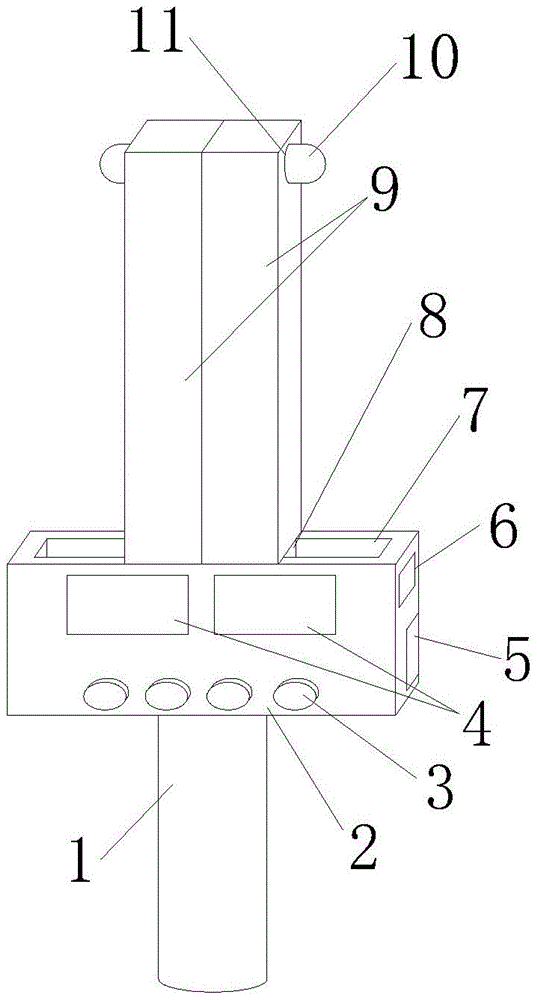
FIG. 2 is an elevation view of the overall structure of one embodiment of the present application;
FIG. 3 is a cross-sectional view of a bar block top structure according to one embodiment of the present application.
In the figure: 1. the device comprises a holding barrel, 2, a rectangular block, 3, an electric control switch, 4, a digital display, 5, a bar-shaped cover, 6, a rectangular groove, 7, a bar-shaped sliding groove, 8, a screw hole sliding block, 9, a bar-shaped block, 10, a telescopic contact head, 11, a column groove, 12, a screw rod, 13, a storage battery, 14, a motor, 15, a placing groove, 16, an intelligent controller, 17, a reset spring, 18 and a displacement sensor.
Detailed Description
In order to make the technical solutions better understood by those skilled in the art, the technical solutions in the embodiments of the present application will be clearly and completely described below with reference to the drawings in the embodiments of the present application, and it is obvious that the described embodiments are only partial embodiments of the present application, but not all embodiments. All other embodiments, which can be derived by a person skilled in the art from the embodiments given herein without making any creative effort, shall fall within the protection scope of the present application.
It should be noted that the terms "first," "second," and the like in the description and claims of this application and in the drawings described above are used for distinguishing between similar elements and not necessarily for describing a particular sequential or chronological order. It should be understood that the data so used may be interchanged under appropriate circumstances such that embodiments of the application described herein may be used. Furthermore, the terms "comprises," "comprising," and "having," and any variations thereof, are intended to cover a non-exclusive inclusion, such that a process, method, system, article, or apparatus that comprises a list of steps or elements is not necessarily limited to those steps or elements expressly listed, but may include other steps or elements not expressly listed or inherent to such process, method, article, or apparatus.
In this application, the terms "upper", "lower", "left", "right", "front", "rear", "top", "bottom", "inner", "outer", "middle", "vertical", "horizontal", "lateral", "longitudinal", and the like indicate orientations or positional relationships based on the orientations or positional relationships shown in the drawings. These terms are used primarily to better describe the present application and its embodiments, and are not used to limit the indicated devices, elements or components to a particular orientation or to be constructed and operated in a particular orientation.
Moreover, some of the above terms may be used to indicate other meanings besides the orientation or positional relationship, for example, the term "on" may also be used to indicate some kind of attachment or connection relationship in some cases. The specific meaning of these terms in this application will be understood by those of ordinary skill in the art as appropriate.
Furthermore, the terms "mounted," "disposed," "provided," "connected," and "sleeved" are to be construed broadly. For example, it may be a fixed connection, a removable connection, or a unitary construction; can be a mechanical connection, or an electrical connection; may be directly connected, or indirectly connected through intervening media, or may be in internal communication between two devices, elements or components. The specific meaning of the above terms in the present application can be understood by those of ordinary skill in the art as appropriate.
It should be noted that the embodiments and features of the embodiments in the present application may be combined with each other without conflict.
The guide rail mud groove inspection device in the embodiment can be suitable for guide rail quality inspection, and for example, the guide rail mud groove inspection device is provided in the embodiment.
The alignment tool for aligning the guide rail of the automotive interior part comprises an alignment frame, wherein a movable plate is arranged inside the alignment frame, a thread groove is formed in the top end of the alignment frame, a screw rod is installed inside the thread groove through threads, a rotary handle is fixedly installed at the top end of the screw rod, the bottom end of the screw rod is fixedly connected with the top end of the movable plate through a bearing, a guide rail body is placed at the bottom end of the movable plate, bottom plates are fixedly installed on two sides of the inner wall of the alignment frame, a second installation frame is fixedly installed on two sides of the alignment frame, the screw rod moves downwards in the thread groove by holding the rotary handle to drive the movable plate to move downwards, when the movable plate moves to a certain position, the guide rail body is clamped by the bottom plates and the movable plate, the guide rail body is fixedly connected with the movable plate, and therefore when butt joint is reduced, the guide rail body moves up and down in the alignment frame, thereby affecting the situation of docking accuracy.
The guide rail mud groove inspection device of the embodiment of the application is introduced below without repeated description.
Referring to fig. 1-3, a guide rail mud groove inspection device comprises a bar-shaped block 9, a telescopic contact head 10, a screw 12, a motor 14, an intelligent controller 16 and a displacement sensor 18, wherein the end face of the bottom end of the bar-shaped block 9 is in threaded connection with the screw 12 through a screw slider 8, the screw 12 is rotatably installed in a bar-shaped sliding groove 7, the end face of one end of the screw 12 is connected with the shaft rod end of the motor 14, the telescopic contact head 10 is slidably installed in a column groove 11, the displacement sensor 18 is installed on the end face of the telescopic contact head 10 located in the column groove 11, the intelligent controller 16 is electrically connected with the motor 14, the displacement sensor 18 and a digital display 4 through wires, the intelligent controller 16 is installed in a placement groove 15, and the placement groove 15 is formed in the bottom of the back face of a rectangular block 2.
Two strip-shaped blocks 9 are arranged, and the two strip-shaped blocks 9 are mutually separated and combined through a rotating screw 12; the column groove 11 is formed in the top of the side wall of one side of the bar-shaped block 9, a return spring 17 is arranged in the column groove 11, two ends of the return spring 17 are respectively connected with the bottom of the column groove 11 and the end face of the inner end of the telescopic contact head 10, and the outer end of the telescopic contact head 10 is of a smooth hemispherical block structure; two digital display devices 4 are arranged, and the two digital display devices 4 are symmetrically arranged on the front end face of the rectangular block 2; a placing groove 15 is formed in the top of the end face of one end of the rectangular block 2, the placing groove 15 is fixedly connected with a motor 14, a holding cylinder 1 is installed on the surface of the bottom of the rectangular block 2, and a storage battery 13 is installed in the holding cylinder 1; the strip-shaped cover 5 is installed at the notch of the placing groove 15, and the threaded structure of the screw 12 is an equal-length reverse threaded structure.
When the mud groove detection device is used, the screw 12 is driven to rotate by the operation motor 14, and under the mutual action of force, the two strip-shaped blocks 9 connected through the screw hole sliding block 8 can move back to back or move oppositely, so that the effect of changing the distance between the two strip-shaped blocks 9 is achieved, the mud groove detection device is convenient to adjust and use according to the width of the mud groove, and the telescopic contact head 10 for detection is favorably contacted with the groove wall;
when the operation finishes and the whole mud groove is pushed to move, the telescopic contact head 10 elastically connected through the reset spring 17 moves along the side wall of the mud groove and under the action of the displacement sensor 18, the convex-concave change condition of the side wall of the mud groove can be measured, the detection of whether the wall of the mud groove is flat or not in a standard range is facilitated, the two digital display displays 4 are arranged, the numerical values displayed on the side walls of the two sides of the mud groove at the same time can be conveniently observed, and the detection efficiency is improved.
The application has the advantages that:
1. the device has a reasonable structure, can move the two strip-shaped blocks 9 connected by the screw hole sliding block 8 back to back or oppositely, achieves the effect of changing the distance between the two strip-shaped blocks 9, is convenient to adjust and use according to the width of the mud groove, and is beneficial to contacting the telescopic contact head 10 for detection with the groove wall;
2. this application is rational in infrastructure, can measure out the convex-concave situation of change of mud groove lateral wall, does benefit to and detects the mud groove cell wall and levels whether in standard range, and sets up two digital display 4, is convenient for observe the numerical value that mud groove both sides lateral wall presented simultaneously, improves detection efficiency.
The above description is only a preferred embodiment of the present application and is not intended to limit the present application, and various modifications and changes may be made by those skilled in the art. Any modification, equivalent replacement, improvement and the like made within the spirit and principle of the present application shall be included in the protection scope of the present application.