SUMMERY OF THE UTILITY MODEL
Aiming at the technical problems that the buffering effect is poor and the impact force caused by collision cannot be effectively reduced, the utility model provides the buffering guardrail for the expressway, which has the advantages of reasonable design, simple structure and convenience in processing, and can effectively improve the buffering effect, reduce the impact force caused by collision and reduce the damage of automobiles.
In order to achieve the purpose, the technical scheme adopted by the utility model is that the buffer guardrail for the expressway comprises a base designed into a trapezoid table, a U-shaped supporting part is arranged at the upper end of the base, the supporting part comprises two vertical rods and a transverse rod which are arranged on the left and right, a vertical rod is arranged between the two vertical rods, a clamping groove is arranged in the front end of each vertical rod, supporting plates are arranged on the upper and lower parts of the front end surface of each vertical rod and the upper and lower parts of the front end surface of each vertical rod respectively, sliding grooves are arranged in the two supporting plates and correspond to each other, a U-shaped mounting frame is arranged between the two supporting plates, sliding blocks are arranged at the upper and lower ends of the U-shaped mounting frame and correspond to the sliding grooves, a buffer cylinder is arranged in the U-shaped mounting frame, a connecting lug is arranged at the rear end of the U-shaped mounting frame, a buffer mechanism is arranged on one side of the connecting lug and connected with the clamping groove, and a spring connecting rod is further arranged at the geometric center of the rear end of the U-shaped mounting frame and is connected with the vertical rod.
Preferably, the transverse supporting rod is arranged at the lower end between the two vertical rods, the two vertical supporting rods are arranged between the two vertical rods at equal intervals, the two clamping grooves are symmetrically arranged in the front ends of the vertical rods, a protection plate is arranged at the upper end of the supporting part, a guardrail plate is arranged at the front end of each supporting plate, the buffer cylinder can rotate left and right relative to the U-shaped mounting frame, the two connecting lugs are symmetrically arranged close to and relative to the geometric center line of the rear end face of the U-shaped mounting frame, and the two buffer mechanisms are symmetrically arranged and are connected with the connecting lugs and the clamping grooves at the left end and the right end respectively.
As preferred, guard plate upper end be provided with the gag lever post, the material of buffer cylinder be polyurethane, buffer gear including controlling movable rod and the fixture block that sets up, movable rod and connecting rod and movable rod and fixture block link together by the fixed pin, the fixture block joint in the draw-in groove, the buffer gear periphery be provided with the safety cover, the safety cover all set up the preceding terminal surface at pole setting and upright pole, the safety cover front end seted up the through-hole.
Compared with the prior art, the utility model has the advantages and positive effects that,
1. the buffering guardrail for the highway provided by the utility model can enable the collided buffering cylinder to move backwards through the matching arrangement of the sliding block and the sliding groove, so as to improve the buffering effect of the guardrail, through the mutual matching arrangement of the movable rod, the movable clamping block and the clamping groove in the buffering mechanism, under the action of impact, the movable clamping block moves in the clamping block, so that impact potential energy can be converted into mechanical energy, thereby achieving the purpose of energy leakage, reducing the damage caused by impact force, effectively dispersing the impact force of the vehicle impacting the buffer guardrail through the arranged buffer cylinder, and the impact force is guided to the buffer guardrail, the impact force brought by the vehicle is transferred as much as possible, thereby the impact force that the collision brought has been reduced, has improved the security of buffering guardrail greatly, improves buffering effect, further ensures vehicle and crew's safety by bus.
Detailed Description
In order that the above objects, features and advantages of the present invention can be more clearly understood, the present invention will be further described with reference to the accompanying drawings and examples. It should be noted that the embodiments and features of the embodiments of the present application may be combined with each other without conflict.
In the following description, numerous specific details are set forth in order to provide a thorough understanding of the present invention, however, the present invention may be practiced in other ways than those specifically described herein, and thus the present invention is not limited to the specific embodiments of the present disclosure.
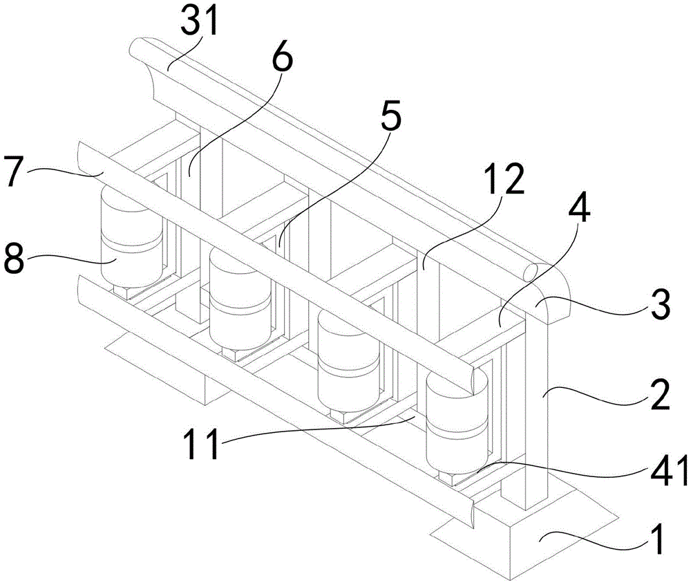
An embodiment, as shown in fig. 1, fig. 2, and fig. 3, a buffering guardrail for a highway includes a base 1 designed as a trapezoid table, when the buffering guardrail is installed, the base 1 is buried underground to fix and limit the installation position of the buffering guardrail, and improve the stability and firmness after the installation of the device is completed, so as to facilitate the impact force of the vehicle colliding with the buffering guardrail, in order to provide favorable installation conditions for each device, a U-shaped supporting member is disposed at the upper end of the base 1, the supporting member includes two vertical rods 2 and two transverse rods 11 disposed at left and right sides, a vertical rod 12 is disposed between the two vertical rods 2, the two vertical rods 2 are disposed at the end of the device, and the transverse rod 11 is disposed between the vertical rods 2, thereby forming a U-shape, which not only has better stability, but also facilitates the installation of the vertical rod 12, further illustrated is that: a plurality of vertical supporting rods 12 can be arranged between two vertical rods 2, so that mounting positions can be provided for a plurality of supporting plates 4, the placing quantity of the buffer cylinders 8 is increased to a certain degree, clamping grooves 21 are arranged in the front ends of the vertical rods 2, the purpose is to provide space for placing the buffer mechanism 10 so as to ensure smooth installation of the device, in order to ensure that the arrangement of each part is more stable, the supporting plates 4 are arranged on the upper part and the lower part of the front end surface of each vertical rod 2 and the upper part and the lower part of the front end surface of each vertical supporting rod 12, sliding grooves 41 are arranged in the two supporting plates 4 and correspond to each other, so that the placing quantity of the buffer cylinders 8 is increased, the buffer cylinders 8 can move when being impacted by the sliding grooves 41, the purpose of energy leakage is achieved, the buffer effect of the buffer guardrail on the impact force is also improved, in order to effectively relieve the impact force generated by vehicle impact, U-shaped mounting frames 5 are arranged between the two supporting plates 4, for buffer tube 8 provides the mounted position, both ends all are provided with slider 51 and correspond with spout 41 about U type mounting bracket 5, in order to improve the fluency that removes the in-process, be provided with buffer tube 8 in the U type mounting bracket 5, buffer tube 8's material is polyurethane rubber, its wear resistance is the best among all rubbers, and intensity is high, elasticity is good, buffering shock attenuation nature is good, can absorb the produced vibrations energy of striking, the frequency of its vibrations is higher, energy absorption is bigger, still have stronger firmness and better shock resistance simultaneously, when the vehicle bumps, can absorb the produced impact energy of striking, greatly alleviate the injury to the vehicle and the driver that are bumped, it needs further to explain: the buffer cylinder 8 can generate relative rotation while realizing the front and back movement, the rolling friction replaces the traditional rigid contact friction, thus the vehicle can deviate from the driving direction, the impact force brought by the vehicle is guided to deviate to the buffer guardrail, the impact force brought by the vehicle is transferred as much as possible, thereby the impact force brought by the collision is reduced, the safety of the buffer guardrail is greatly improved, the buffer effect is improved, the safety of the vehicle and passengers is further ensured, in order to ensure the buffer structure to run smoothly, the connecting lug 52 is arranged at the rear end of the U-shaped mounting rack 5, the buffer mechanism 10 is arranged at one side of the connecting lug 52 and connected with the clamping groove 21, the buffer mechanism 10 can rotate relative to the connecting lug 52 to ensure that the buffer cylinder 8 can move backwards smoothly, thereby the energy discharge purpose is achieved, the spring connecting rod 9 is also arranged at the geometric center of the rear end of the U-shaped mounting rack 5 and connected with the upright rod 2, the spring connecting rod 9 can also buffer the U-shaped mounting rack 5 to a certain extent, so that the buffering effect of the buffering guardrail on the impact force is further improved, and the safety of vehicles and personnel is ensured; in summary, the following steps: through the cooperation setting of slider 51 and spout 41, can make the buffer cylinder 8 that receives the collision move backward, in order to improve the buffering effect of guardrail, through the movable rod 101 among buffer gear 10 and the setting of mutually supporting between removal fixture block 102 and draw-in groove 21, under the effect of strikeing, remove fixture block 102 and remove in the fixture block, can convert impact potential energy into mechanical energy like this, and then reach the mesh of earning, the damage that the impact force brought has been reduced, through the buffer cylinder 8 that sets up, can bump the vehicle to the impact force of buffering guardrail and effectively disperse, and guide the impact force to the buffering guardrail, the impact force that the vehicle brought is fallen in as much as possible transfer, thereby the impact force that the collision brought has been reduced, the security of buffering guardrail has been improved greatly, the buffering effect is improved, further guarantee vehicle and personnel's safety by bus.
In order to improve the stability of the device and the reasonableness of the design, the transverse support rod 11 is arranged at the lower end between the two vertical rods 2, the firmness among all parts can be improved while installation positions are provided for other parts, the two vertical support rods 12 are equidistantly arranged between the two vertical rods 2, the arrangement of the buffer cylinder 8 is facilitated, the two clamping grooves 21 are symmetrically arranged in the front end of the vertical rods 2, the connection with the clamping blocks is conveniently realized, conditions are provided for buffering and energy discharge, the upper end of the support part is provided with the protection plate 3, so that collision vehicles are protected, the collision vehicles are prevented from flying out of the upper end of the buffer guardrail, the occurrence of damage is reduced, the front ends of the two support plates 4 are respectively provided with the guardrail plate 7, the guardrail plates 7 are matched with the buffer cylinder 8, the friction force between the vehicles and the buffer guardrails can be improved, the vehicles can be stopped more quickly, the buffer cylinder 8 can rotate left and right relative to the U-type installation frame 5, like this when colliding with the car, can convert impact potential energy into rolling mechanical energy, and then reach the purpose of buffering, in order to make the device installation more convenient, the save time cost, two engaging lugs 52 are close to and set up about the geometric centre line symmetry of U type mounting bracket 5 rear end face, engaging lug 52 provides favorable installation condition for buffer gear 10, two buffer gear 10 symmetries set up and its left and right sides both ends are connected with engaging lug 52 and draw-in groove 21 respectively, it is more reasonable to design, the practicality is stronger.
In order to improve the practicability of the buffer guardrail, the upper end of the protection plate 3 is provided with the limiting rod 31 which can further intercept the collided vehicles and avoid larger-scale damage caused by the collided vehicles, the buffer cylinder 8 is made of polyurethane, the polyurethane has wide hardness range and high strength, so that the adjustable range of the performance is large, and the buffer cylinder has better wear resistance and shock absorption performance, in order to realize the reduction of the impact force by the buffer mechanism 10, the buffer mechanism 10 comprises a movable rod 101 and a clamping block which are arranged on the left and right sides, the movable rod 101 and a connecting rod are connected with the movable rod 101 and the clamping block by fixing pins, and the clamping block is clamped in the clamping groove 21, in the process, when an automobile collides against the buffer cylinder 8, the clamping block moves upwards in the clamping groove 21 under the action of the impact force, so that the potential energy caused by the impact can be converted into mechanical energy, the purpose of energy leakage is achieved, and the damage caused by the impact force is reduced, in order to avoid buffer gear 10 to expose outside and receive the influence of other impurity such as dust, buffer gear 10 periphery is provided with safety cover 6, safety cover 6 all sets up the preceding terminal surface in pole setting 2 and perpendicular branch 12, effectively completely cut off impurity such as dust, thereby guarantee that buffer gear 10 can move smoothly, the through-hole has been seted up to safety cover 6 front end, and the length and the width of through-hole slightly are greater than the length width of U type mounting bracket 5, like this when the buffering striking, so that the passing through of mounting bracket 5, and then reach the purpose of earning.
The above description is only a preferred embodiment of the present invention, and not intended to limit the present invention in other forms, and any person skilled in the art may apply the above modifications or changes to the equivalent embodiments with equivalent changes, without departing from the technical spirit of the present invention, and any simple modification, equivalent change and change made to the above embodiments according to the technical spirit of the present invention still belong to the protection scope of the technical spirit of the present invention.