Tension control device of adhesive tape rewinding machine
Technical Field
The utility model relates to the technical field of rewinding machines, in particular to a tension control device of an adhesive tape rewinding machine.
Background
The adhesive tape is a tool with adhesive surface, two objects can be connected through adhesion to be adhered and fixed, the adhesive tape can be divided into different types according to different using ways, box sealing adhesive tapes, double-sided adhesive tapes, warning adhesive tapes and the like are common, the adhesive tape needs to be wound by a rewinding machine in the production process, and then a finished product can be formed, but some problems exist in the winding process, such as the case;
in the rewinding process, the situation that the adhesive tape is loosened frequently occurs, the coiling material is irregular due to too small tension, the product quality is affected, the tension control device is required to adjust the tension of the adhesive tape, the adhesive tape always bears the optimal tension in the winding process, and the conventional tension control device cannot be conveniently adjusted, so that the adhesive tape is broken and the adhesive tape layer is subjected to stress deformation.
In order to solve the above problems, innovative design based on the original tension control device is urgently needed.
SUMMERY OF THE UTILITY MODEL
The utility model aims to provide a tension control device of an adhesive tape rewinding machine, which aims to solve the problem of looseness in the adhesive tape winding process in the background technology.
In order to achieve the purpose, the utility model provides the following technical scheme: a tension control device of a tape rewinding machine comprises a base body, a tension roller, a telescopic rod, an indicating block and a clamping block, wherein a mounting plate is fixedly mounted at the side end of the base body, a roller is fixedly mounted on the outer surface of the mounting plate, a chute is formed in the side end of the outer surface of the base body, a connecting rod is connected to the inner side of the chute, the outer surface of the connecting rod is connected with the tension roller, a butt joint rod is fixedly connected to the tail end of the connecting rod, a first rack is connected to the inner side of the butt joint rod, the outer side of the first rack is connected with a first gear, the inner side of the first gear is connected with a sleeve, the inner side of the sleeve is connected with an output end of the telescopic rod, the telescopic rod is fixedly mounted in the base body, a second rack is fixedly connected to the outer surface of the output end of the telescopic rod, the outer side of the second rack is connected with a second gear, and a fixed shaft is fixedly connected to the inner side of the second gear, and the end of fixed axle is connected with the movable block, the surface side fixed mounting of base member has the installation piece, the side fixed mounting of movable block has the instruction piece, and the inner fixed mounting of movable block has the fixed block, the fixed block is connected with the movable block through the connecting axle, and the inside of connecting axle is provided with torque spring, the draw-in groove has been seted up to the surface of installation piece, and the inboard of draw-in groove is connected with the block to the block is connected with the movable block.
Preferably, the rollers are symmetrically distributed in two groups about the transverse center line of the substrate, and the mounting plates and the rollers are symmetrically distributed in two groups about the longitudinal center line of the substrate.
Preferably, the tension roller forms a sliding structure with the base body through the sliding groove, the connecting rod and the butt joint rod are connected in an L-shaped structure in side view, and the first rack is in meshed connection with the first gear.
Preferably, the inner side of the sleeve is in threaded connection with the output end of the telescopic rod, and the second rack is in meshed connection with the second gear.
Preferably, the movable block is rotatably connected with the mounting block, and the movable block and the fixed block form an elastic structure through a torsion spring.
Preferably, the clamping block and the movable block are connected in a welding manner, and the clamping block and the clamping groove are in a clamping structure.
Compared with the prior art, the utility model has the beneficial effects that: the tension control device of the adhesive tape rewinding machine;
1. the device is provided with tension rollers, and the two groups of butt-joint rods are driven by gears to move up and down in opposite directions, so that the tension rollers at the tail ends of the connecting rods move synchronously, and therefore the adhesive tape connected between the two groups of tension rollers is tensioned, the adhesive tape is changed from a loose state, and winding work is stably carried out;
2. be provided with the movable block, drive the rotation of movable block through the handle for the telescopic link can stabilize work, and the block structure of block and draw-in groove can be fixed the movable block moreover, makes the tension roller keep invariable tension, can also carry out marking of tension data through instructing block and scale mark.
Drawings
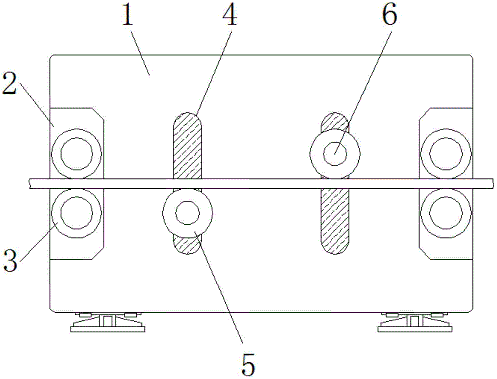
FIG. 1 is a schematic front view of the present invention;
FIG. 2 is a schematic top sectional view of the present invention;
FIG. 3 is a schematic side view of the telescopic rod of the present invention;
FIG. 4 is a schematic side view of the movable block of the present invention.
In the figure: 1. a substrate; 2. mounting a plate; 3. rolling; 4. a chute; 5. a tension roller; 6. a connecting rod; 7. a docking rod; 8. a first rack; 9. a first gear; 10. a sleeve; 11. a telescopic rod; 12. a second rack; 13. a second gear; 14. a fixed shaft; 15. mounting blocks; 16. a movable block; 17. an indication block; 18. a fixed block; 19. a connecting shaft; 20. a torsion spring; 21. a card slot; 22. and a clamping block.
Detailed Description
The technical solutions in the embodiments of the present invention will be clearly and completely described below with reference to the drawings in the embodiments of the present invention, and it is obvious that the described embodiments are only a part of the embodiments of the present invention, and not all of the embodiments. All other embodiments, which can be derived by a person skilled in the art from the embodiments given herein without making any creative effort, shall fall within the protection scope of the present invention.
Referring to fig. 1-4, the present invention provides a technical solution: a tension control device of a tape rewinding machine comprises a base body 1, a mounting plate 2, a roller 3, a chute 4, a tension roller 5, a connecting rod 6, a butt joint rod 7, a first rack 8, a first gear 9, a sleeve 10, a telescopic rod 11, a second rack 12, a second gear 13, a fixed shaft 14, a mounting block 15, a movable block 16, an indicating block 17, a fixed block 18, a connecting shaft 19, a torsion spring 20, a clamping groove 21 and a clamping block 22, wherein the mounting plate 2 is fixedly mounted at the side end of the base body 1, the roller 3 is fixedly mounted on the outer surface of the mounting plate 2, the chute 4 is formed in the side end of the outer surface of the base body 1, the connecting rod 6 is connected to the inner side of the chute 4, the tension roller 5 is connected to the outer surface of the connecting rod 6, the butt joint rod 7 is fixedly connected to the tail end of the connecting rod 6, the first rack 8 is connected to the inner side of the butt joint rod 7, and the outer side of the first rack 8 is connected with the first gear 9, the inner side of the first gear 9 is connected with a sleeve 10, the inner side of the sleeve 10 is connected with the output end of a telescopic rod 11, and the telescopic rod 11 is fixedly arranged inside the base body 1, the outer surface of the output end of the telescopic rod 11 is fixedly connected with a second rack 12, and the outer side of the second rack 12 is connected with a second gear 13, the inner side of the second gear 13 is fixedly connected with a fixed shaft 14, the tail end of the fixed shaft 14 is connected with a movable block 16, the side end of the outer surface of the base body 1 is fixedly provided with a mounting block 15, the side end of the movable block 16 is fixedly provided with an indicating block 17, and the inner end of the movable block 16 is fixedly provided with a fixed block 18, the fixed block 18 is connected with the movable block 16 through a connecting shaft 19, a torsion spring 20 is arranged in the connecting shaft 19, a clamping groove 21 is arranged on the outer surface of the mounting block 15, the inner side of the slot 21 is connected with a clamping block 22, and the clamping block 22 is connected with the movable block 16;
the roll 3 is two sets of about the horizontal centerline symmetric distribution of base member 1, and mounting panel 2 and roll 3 are two sets of about the vertical centerline symmetric distribution of base member 1, tension roller 5 passes through spout 4 and constitutes sliding construction with base member 1, and connecting rod 6 and butt joint pole 7 look sideways at and be "L" style of calligraphy structure and be connected, and first rack 8 and first gear 9 are connected for the meshing, the inboard and 11 output ends of telescopic link of sleeve 10 are threaded connection, and second rack 12 is connected for the meshing with second gear 13, carry out tension control through tension roller 5 to the sticky tape, make it carry out the rolling under stable tension degree.
The movable block 16 is rotatably connected with the mounting block 15, the movable block 16 and the fixed block 18 form an elastic structure through a torsion spring 20, the clamping block 22 and the movable block 16 are connected in a welding manner, the clamping block 22 and the clamping groove 21 form a clamping structure, and the tension roller 5 is fixed in position through the clamping structures of the clamping block 22 and the clamping groove 21, so that the adhesive tape is wound under the action of constant tension.
The working principle is as follows: when the tension control device of the adhesive tape rewinding machine is used, according to the figure 1, the device is firstly placed at a position needing to work, an adhesive tape penetrates between two groups of rollers 3 at the left end of a base body 1, bypasses a tension roller 5, penetrates out between two groups of rollers 3 at the right end, is fixed on a winding mechanism of the rewinding machine, and then rewinding work is carried out, when the adhesive tape is loosened in the rewinding process, a user can push a handle to lift a movable block 16 at the moment so that a clamping groove 21 and a clamping block 22 are separated from a clamping structure, then the movable block 16 is rotated by rotating the handle, so that a second gear 13 at the tail end of a fixed shaft 14 is driven to synchronously rotate, the output end of a telescopic rod 11 is driven to extend, and when the output end of the telescopic rod 11 extends, a sleeve 10 drives a first gear 9 to rotate clockwise under the effect of threaded connection, make the first rack 8 that the meshing is connected remove, drive two sets of butt joint pole 7 and connecting rod 6 simultaneously and remove in opposite directions, make left side tension roller 5 skew upwards, right side tension roller 5 skew downwards, the tensioning of flare-outing the sticky tape, after adjusting to the appropriate degree of tensioning, loosen the handle, make movable block 16 reset under torque spring 20's effect, block 22 will be blocked with draw-in groove 21 looks again simultaneously, indicate block 17 to rotate along with movable block 16, make and indicate block 17 scale mark on installation block 15 line position, make the operator obtain accurate data to the tensioning dynamics, holistic practicality has been increased.
Those not described in detail in this specification are within the skill of the art.
Although embodiments of the present invention have been shown and described, it will be appreciated by those skilled in the art that changes, modifications, substitutions and alterations can be made in these embodiments without departing from the principles and spirit of the utility model, the scope of which is defined in the appended claims and their equivalents.