CN216102207U - Mounting platform for tunnel electromechanical equipment - Google Patents
Mounting platform for tunnel electromechanical equipment Download PDFInfo
- Publication number
- CN216102207U CN216102207U CN202122469583.0U CN202122469583U CN216102207U CN 216102207 U CN216102207 U CN 216102207U CN 202122469583 U CN202122469583 U CN 202122469583U CN 216102207 U CN216102207 U CN 216102207U
- Authority
- CN
- China
- Prior art keywords
- box
- rod
- containing box
- electromechanical
- plate
- Prior art date
- Legal status (The legal status is an assumption and is not a legal conclusion. Google has not performed a legal analysis and makes no representation as to the accuracy of the status listed.)
- Expired - Fee Related
Links
- 230000002441 reversible effect Effects 0.000 claims description 17
- 210000001503 joint Anatomy 0.000 claims description 5
- 238000009434 installation Methods 0.000 abstract description 5
- 238000000034 method Methods 0.000 abstract description 3
- 230000007306 turnover Effects 0.000 description 2
- 229910001294 Reinforcing steel Inorganic materials 0.000 description 1
- 230000009286 beneficial effect Effects 0.000 description 1
- 230000007547 defect Effects 0.000 description 1
- 230000035939 shock Effects 0.000 description 1
- 230000001360 synchronised effect Effects 0.000 description 1
- XLYOFNOQVPJJNP-UHFFFAOYSA-N water Substances O XLYOFNOQVPJJNP-UHFFFAOYSA-N 0.000 description 1
Images


Landscapes
- Handcart (AREA)
Abstract
The utility model discloses an installation platform for tunnel electromechanical equipment, which comprises connecting rods, a top plate and a bottom plate, wherein the top of the bottom plate is fixedly provided with the connecting rods, a holding handle is fixedly arranged between the connecting rods, the top of the bottom plate at the front end of the connecting rods is fixedly provided with an accommodating box, an organic electronic box is arranged in the accommodating box in a sliding mode, a threaded rod is movably arranged between the electromechanical box and the accommodating box and extends out of the accommodating box, and telescopic rods are fixedly arranged at the tops of the bottom plates at two sides of the accommodating box. According to the utility model, the electromechanical equipment can be transferred conveniently by arranging the containing box and matching the electromechanical box with the rotating plate, the electromechanical equipment can be protected by the containing box from being damaged due to collision with an external object in the transportation process, the safety is improved, the electromechanical equipment can be taken out of the containing box conveniently by the electromechanical box, the electromechanical box is supported by matching the rotating plate, the electromechanical equipment can be taken out and installed conveniently by a worker, and the electromechanical equipment is convenient and rapid.
Description
Technical Field
The utility model relates to the technical field of electromechanical equipment, in particular to an installation platform for tunnel electromechanical equipment.
Background
Electromechanical equipment generally refers to machinery, electrical equipment and electric automation equipment, and in a building, the machinery except geotechnics, woodwork, reinforcing steel bars and muddy water and the pipeline equipment are generally called, which is different from hardware and can realize finished products with certain functions.
Through the retrieval, patent publication number is CN209430971U discloses an electromechanical device installing support, and this utility model discloses an electromechanical device installing support, including base, support and supporting platform, base upper end both ends symmetry is equipped with the support, the support inboard is equipped with supporting platform, supporting platform lower extreme symmetry is equipped with the shock attenuation post, base upper end middle part is equipped with the spout, the symmetry is equipped with two slip posts on the spout, and two slip posts pass through the telescopic link and connect, telescopic link outside suit supporting spring, slip post upper end hinge support pole, the other end hinge support platform of bracing piece.
The existing mounting platform of electromechanical equipment has the following defects:
1. when the existing electromechanical equipment mounting platform is used, the electromechanical device is inconvenient to transfer, so that workers need to transfer the electromechanical equipment to other places for mounting, the electromechanical equipment is easy to collide in the transportation process, the equipment is damaged, the working strength of the workers is improved, the working efficiency is reduced, and more inconvenience is brought to electromechanical mounting work;
2. the mounting platform of general electromechanical device does not have better mounting platform, and inconvenient regulation mounted position when installing leads to bringing inconvenience for the installation work, has reduced the convenience, for this reason we provide a mounting platform for tunnel electromechanical device to solve current problem.
SUMMERY OF THE UTILITY MODEL
The present invention aims to provide a mounting platform for tunnel electromechanical devices to solve the problems set forth in the above background.
In order to achieve the purpose, the utility model provides the following technical scheme: the utility model provides a mounting platform for tunnel electromechanical device, includes connecting rod, roof and bottom plate, the top fixed mounting of bottom plate has the connecting rod, fixed mounting holds up the hand (hold) between the connecting rod, the bottom plate top fixed mounting of connecting rod front end has the containing box, the inside slidable mounting of containing box has the organic electronic box, movable mounting has the threaded rod between electromechanical box and the containing box, the threaded rod extends the containing box, the bottom plate top fixed mounting of containing box both sides has the telescopic link, the roof is installed in the top butt joint of telescopic link, the front end movable mounting of containing box has the rotor plate, the inside movable mounting of containing box has reverse lead screw, movable mounting has the rotary rod between reverse lead screw and the roof.
Preferably, the bottom plate and the motor case are slidably mounted through a first sliding chute, and the rotating plate is provided with a second sliding chute corresponding to the first sliding chute.
Preferably, the telescopic rod and the top plate are installed in a butt joint mode through the supporting rod, and the telescopic rod and the supporting rod are fixed through the knob.
Preferably, the rotating plate and the storage box are movably mounted through a spring, and a base is fixedly mounted at the front end of the rotating plate.
Preferably, the containing box and the threaded rod are movably mounted through a second threaded sleeve, and a rotating handle is fixedly mounted at the rear end of the threaded rod.
Preferably, the reverse screw rod and the rotary rod are movably mounted through a first thread sleeve, and a handle is fixedly mounted at one end of the reverse screw rod.
Preferably, the bottom of the bottom plate is fixedly provided with universal wheels, and the top of the top plate is fixedly provided with a mounting plate.
Compared with the prior art, the utility model has the beneficial effects that:
1. according to the utility model, the electromechanical equipment can be transferred conveniently by arranging the containing box and matching the electromechanical box with the rotating plate, the electromechanical equipment can be protected by the containing box from being damaged due to collision with an external object in the transportation process, the safety is improved, the electromechanical equipment can be taken out of the containing box conveniently by the electromechanical box, the electromechanical box is supported by matching the rotating plate, the electromechanical equipment can be taken out and installed conveniently by a worker, and the electromechanical equipment is convenient and rapid.
2. The electromechanical equipment can be conveniently placed on the top plate by arranging the mutual matching between the top plate and the rotary rod, the top plate is movably supported by the rotary rod, the mounting position can be conveniently adjusted, more convenience is brought to mounting work of operators, and the convenience is effectively improved.
Drawings
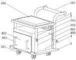
FIG. 1 is a schematic external perspective view of a first embodiment of the present invention;
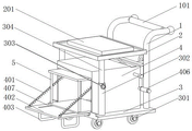
FIG. 2 is a perspective view of a second embodiment of the present invention;
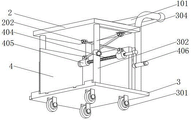
FIG. 3 is a schematic front view of the present invention;
FIG. 4 is a schematic view of a partial structure of the electromechanical housing of the present invention;
fig. 5 is a schematic view of the reverse screw structure of the present invention.
In the figure: 1. a connecting rod; 101. a handle bar; 2. a top plate; 201. mounting a plate; 202. rotating the rod; 3. a base plate; 301. a universal wheel; 302. a telescopic rod; 303. a knob; 304. a support bar; 305. a first chute; 4. a storage box; 401. a spring; 402. a rotating plate; 403. a base; 404. a reverse screw rod; 405. a first threaded sleeve; 406. a grip; 407. a second chute; 5. an electromechanical box; 501. a second threaded sleeve; 502. a threaded rod; 503. and (4) turning the handle.
Detailed Description
The technical solutions in the embodiments of the present invention will be clearly and completely described below with reference to the drawings in the embodiments of the present invention, and it is obvious that the described embodiments are only a part of the embodiments of the present invention, and not all of the embodiments. All other embodiments, which can be derived by a person skilled in the art from the embodiments given herein without making any creative effort, shall fall within the protection scope of the present invention.
In the description of the present invention, it should be noted that the terms "upper", "lower", "inner", "outer", "front", "rear", "both ends", "one end", "the other end", and the like indicate orientations or positional relationships based on those shown in the drawings, and are only for convenience of description and simplicity of description, but do not indicate or imply that the referred device or element must have a specific orientation, be constructed in a specific orientation, and be operated, and thus, should not be construed as limiting the present invention. Furthermore, the terms "first" and "second" are used for descriptive purposes only and are not to be construed as indicating or implying relative importance.
In the description of the present invention, it is to be noted that, unless otherwise explicitly specified or limited, the terms "mounted," "disposed," "connected," and the like are to be construed broadly, such as "connected," which may be fixedly connected, detachably connected, or integrally connected; can be mechanically or electrically connected; they may be connected directly or indirectly through intervening media, or they may be interconnected between two elements. The specific meanings of the above terms in the present invention can be understood in specific cases to those skilled in the art.
Referring to fig. 1-5, an embodiment of the present invention is shown: a mounting platform for tunnel electromechanical equipment comprises a connecting rod 1, a top plate 2 and a bottom plate 3, wherein universal wheels 301 are fixedly mounted at the bottom of the bottom plate 3 through bolts, the connecting rod 1 is fixedly mounted at the top of the bottom plate 3 through bolts, a holding handle 101 is fixedly mounted between the connecting rods 1 through bolts, the device is moved to a proper position through pushing the holding handle 101 by utilizing the universal wheels 301, a containing box 4 is fixedly mounted at the top of the bottom plate 3 at the front end of the connecting rod 1, an organic electronic box 5 is slidably mounted in the containing box 4 through a first chute 305, a threaded rod 502 is movably mounted between the organic electronic box 5 and the containing box 4 through a second threaded sleeve 501, the threaded rod 502 extends out of the containing box 4, a rotating handle 503 is fixedly mounted at the rear end of the threaded rod 502 through bolts, the rotating handle 503 drives the threaded rod 502 to rotate, the electric box 5 is driven to slide along the first chute 305 by utilizing the second threaded sleeve 501, the front end of the containing box 4 is movably provided with a rotating plate 402 through a spring 401, the rotating plate 402 is provided with a second chute 407 corresponding to the first chute 305, the front end of the rotating plate 402 is fixedly provided with a base 403 through a bolt, when the electromechanical box 5 slides along the first chute 305, the rotating plate 402 can be pushed to turn over, so that the electromechanical box 5 continuously slides along the second chute 407, the electromechanical box 5 is moved out of the containing box 4 and is supported by the base 403, the electromechanical device is conveniently placed on the electromechanical box 5 and is conveniently taken out, and the spring 401 is used for conveniently driving the rotating plate 402 to turn over and reset;
the top of the bottom plate 3 at two sides of the containing box 4 is fixedly provided with an expansion link 302 through a bolt, the top of the expansion link 302 is provided with a top plate 2 through a support rod 304 in a butt joint manner, the expansion link 302 and the support rod 304 are fixed through a knob 303, the top of the top plate 2 is fixedly provided with a mounting plate 201 through a bolt, electromechanical equipment can be placed on the mounting plate 201, the containing box 4 is movably provided with a reverse lead screw 404 inside, the reverse lead screw 404 and the top plate 2 are movably provided with a rotary rod 202 through a movable joint, the reverse lead screw 404 and the rotary rod 202 are movably mounted through a first thread sleeve 405, one end of the reverse lead screw 404 is fixedly provided with a handle 406 through a bolt, the reverse lead screw 404 is driven to rotate through the handle 406, the first thread sleeve 405 moves relative to the reverse lead screw 404, the top plate 2 is supported and lifted by the rotary rod 202, and the installation position can be conveniently adjusted by an operator according to the installation requirement, synchronous drive bracing piece 304 is flexible, fixes between with telescopic link 302 and bracing piece 304 through knob 303, conveniently supports roof 2.
The working principle is as follows: when the mounting platform for the tunnel electromechanical equipment is used, the device is moved to a proper position through the universal wheel 301, the threaded rod 502 is driven to rotate through the rotating handle 503, the motor electric box 5 is driven to slide along the first sliding groove 305 by the second threaded sleeve 501, the rotating plate 402 is pushed to turn to a horizontal state, the base 403 is used for supporting, the motor electric box 5 slides to the rotating plate 402, the electromechanical equipment is taken out and placed on the mounting plate 201, the reverse screw rod 404 is driven to rotate through the handle 406, the first threaded sleeve 405 is driven to move relatively, the top plate 2 is lifted by the rotating rod 202, and therefore a series of operations of the mounting platform for the tunnel electromechanical equipment are completed.
It will be evident to those skilled in the art that the utility model is not limited to the details of the foregoing illustrative embodiments, and that the present invention may be embodied in other specific forms without departing from the spirit or essential attributes thereof. The present embodiments are therefore to be considered in all respects as illustrative and not restrictive, the scope of the utility model being indicated by the appended claims rather than by the foregoing description, and all changes which come within the meaning and range of equivalency of the claims are therefore intended to be embraced therein. Any reference sign in a claim should not be construed as limiting the claim concerned.
Claims (7)
1. A mounting platform for tunnel electromechanical device, includes connecting rod (1), roof (2) and bottom plate (3), its characterized in that: the top of the bottom plate (3) is fixedly provided with connecting rods (1), a handrail (101) is fixedly arranged between the connecting rods (1), the top of the bottom plate (3) at the front end of the connecting rod (1) is fixedly provided with a containing box (4), an electromechanical box (5) is slidably arranged in the containing box (4), a threaded rod (502) is movably arranged between the electromechanical box (5) and the containing box (4), the threaded rod (502) extends out of the containing box (4), the top parts of the bottom plates (3) at the two sides of the containing box (4) are fixedly provided with telescopic rods (302), the top of the telescopic rod (302) is provided with a top plate (2) in a butt joint way, the front end of the containing box (4) is movably provided with a rotating plate (402), the inside movable mounting of containing box (4) has reverse lead screw (404), movable mounting has rotary rod (202) between reverse lead screw (404) and roof (2).
2. The mounting platform for a tunnel electromechanical device according to claim 1, wherein: the base plate (3) and the electromechanical box (5) are slidably mounted through a first sliding chute (305), and a second sliding chute (407) corresponding to the first sliding chute (305) is arranged on the rotating plate (402).
3. The mounting platform for a tunnel electromechanical device according to claim 1, wherein: the telescopic rod (302) and the top plate (2) are installed in a butt joint mode through the supporting rod (304), and the telescopic rod (302) and the supporting rod (304) are fixed through the knob (303).
4. The mounting platform for a tunnel electromechanical device according to claim 1, wherein: the rotating plate (402) and the containing box (4) are movably arranged through a spring (401), and a base (403) is fixedly arranged at the front end of the rotating plate (402).
5. The mounting platform for a tunnel electromechanical device according to claim 1, wherein: the containing box (4) and the threaded rod (502) are movably mounted through a second threaded sleeve (501), and a rotating handle (503) is fixedly mounted at the rear end of the threaded rod (502).
6. The mounting platform for a tunnel electromechanical device according to claim 1, wherein: the reverse screw rod (404) and the rotating rod (202) are movably arranged through a first thread sleeve (405), and one end of the reverse screw rod (404) is fixedly provided with a handle (406).
7. The mounting platform for a tunnel electromechanical device according to claim 1, wherein: the bottom of bottom plate (3) fixed mounting has universal wheel (301), and the top fixed mounting of roof (2) has mounting panel (201).
Priority Applications (1)
| Application Number | Priority Date | Filing Date | Title |
|---|---|---|---|
| CN202122469583.0U CN216102207U (en) | 2021-10-14 | 2021-10-14 | Mounting platform for tunnel electromechanical equipment |
Applications Claiming Priority (1)
| Application Number | Priority Date | Filing Date | Title |
|---|---|---|---|
| CN202122469583.0U CN216102207U (en) | 2021-10-14 | 2021-10-14 | Mounting platform for tunnel electromechanical equipment |
Publications (1)
| Publication Number | Publication Date |
|---|---|
| CN216102207U true CN216102207U (en) | 2022-03-22 |
Family
ID=80692463
Family Applications (1)
| Application Number | Title | Priority Date | Filing Date |
|---|---|---|---|
| CN202122469583.0U Expired - Fee Related CN216102207U (en) | 2021-10-14 | 2021-10-14 | Mounting platform for tunnel electromechanical equipment |
Country Status (1)
| Country | Link |
|---|---|
| CN (1) | CN216102207U (en) |
Cited By (1)
| Publication number | Priority date | Publication date | Assignee | Title |
|---|---|---|---|---|
| CN115973976A (en) * | 2023-01-06 | 2023-04-18 | 国网冀北电力有限公司承德供电公司 | A substation equipment installation and maintenance operation platform |
-
2021
- 2021-10-14 CN CN202122469583.0U patent/CN216102207U/en not_active Expired - Fee Related
Cited By (1)
| Publication number | Priority date | Publication date | Assignee | Title |
|---|---|---|---|---|
| CN115973976A (en) * | 2023-01-06 | 2023-04-18 | 国网冀北电力有限公司承德供电公司 | A substation equipment installation and maintenance operation platform |
Similar Documents
| Publication | Publication Date | Title |
|---|---|---|
| CN110952455B (en) | An intelligent assistant robot for bridge guardrail installation | |
| CN117902443A (en) | Lifting device for building construction | |
| CN109687329B (en) | Rear cabinet door positioning device of switch cabinet | |
| CN215711439U (en) | Be used for building electromechanical installation to use electronic auxiliary device | |
| CN211643039U (en) | Tubular product transfer device for machining | |
| CN213115433U (en) | A bridge engineering construction platform | |
| US6675913B2 (en) | Core drilling method and apparatus | |
| CN221191350U (en) | A mobile safety crane | |
| CN216472118U (en) | Supporting device for installation of large-scale factory building | |
| CN218619193U (en) | Stacking machine for corrugated pipe | |
| CN218094612U (en) | Pipe jacking access construction auxiliary equipment in well | |
| CN213917010U (en) | Bolt tightening robot | |
| CN216305318U (en) | Novel construction frame | |
| CN217778582U (en) | Battery replacement equipment | |
| CN209169913U (en) | Cable bearer is used in a kind of laying of circuit | |
| CN211295949U (en) | Lifting service vehicle | |
| CN114495712A (en) | Data display device for reducing variety steel production research and use method thereof | |
| CN212218424U (en) | Auxiliary mounting bracket for electric power engineering | |
| CN216234790U (en) | Mechanical power assisting arm with guiding and pushing structure | |
| CN220446465U (en) | Double-station one-to-two truss robot | |
| CN215846486U (en) | Electric welding with protect function | |
| CN110902623A (en) | Quick opening device suitable for cable trench cover | |
| CN221473824U (en) | Trolley device for electric welding machine to move | |
| CN216587599U (en) | Platform for building construction of building engineering house | |
| CN223632965U (en) | A safety maintenance device for gantry cranes |
Legal Events
| Date | Code | Title | Description |
|---|---|---|---|
| GR01 | Patent grant | ||
| GR01 | Patent grant | ||
| CF01 | Termination of patent right due to non-payment of annual fee | ||
| CF01 | Termination of patent right due to non-payment of annual fee |
Granted publication date: 20220322 |