CN216080102U - Top-outlet outdoor unit and air conditioner with same - Google Patents
Top-outlet outdoor unit and air conditioner with same Download PDFInfo
- Publication number
- CN216080102U CN216080102U CN202121878715.9U CN202121878715U CN216080102U CN 216080102 U CN216080102 U CN 216080102U CN 202121878715 U CN202121878715 U CN 202121878715U CN 216080102 U CN216080102 U CN 216080102U
- Authority
- CN
- China
- Prior art keywords
- air
- control box
- outlet
- outdoor unit
- electric control
- Prior art date
- Legal status (The legal status is an assumption and is not a legal conclusion. Google has not performed a legal analysis and makes no representation as to the accuracy of the status listed.)
- Active
Links
Images


Abstract
The utility model provides a top-outlet air outdoor unit and an air conditioner with the same, relates to the technical field of air conditioning equipment, and aims to solve the problem that the heat dissipation condition inside an electric control box of the existing top-outlet air outdoor unit is poor. The top-outlet air outdoor unit comprises a side plate for forming a casing, an electric appliance cover plate fixedly connected to the side plate and an electric control box arranged on the side plate, wherein an accommodating cavity is formed between the electric appliance cover plate and the side plate, the electric control box is positioned in the accommodating cavity, and an interlayer space is formed between the electric control box and the electric appliance cover plate; the electric control box is provided with an air inlet and a heat dissipation opening, the air inlet is communicated with an air duct of the top air outlet outer machine and an inner cavity of the electric control box, and the heat dissipation opening is communicated with the inner cavity and the interlayer space; the air outlet has been seted up to the curb plate, and air outlet intercommunication intermediate layer space and wind channel, and the air outlet is close to the fan blade setting in the wind channel, and the fan blade setting is kept away from to the air intake. The air conditioner comprises the top air outlet outdoor unit. The utility model ensures that the heat dissipation condition in the electric control box is better.
Description
Technical Field
The utility model relates to the technical field of air conditioning equipment, in particular to a top air outlet outdoor unit and an air conditioner with the same.
Background
Generally, the electronic control box of the top-outlet air-out outdoor unit adopts a sealed structural design, so that the heat dissipation condition inside the electronic control box is very poor in the operation process of the top-outlet air-out outdoor unit, the temperature of an electrical element inside the electronic control box exceeds a safety value in a limit state, the electrical element is overheated and shutdown protection occurs, and under a severe condition, safety accidents such as burning and explosion of the electrical element can also occur, so that great potential safety hazards exist.
SUMMERY OF THE UTILITY MODEL
The first objective of the present invention is to provide a top-outlet outdoor unit, so as to solve the technical problem that the heat dissipation condition inside the electric control box of the existing top-outlet outdoor unit is poor.
The utility model provides a top-outlet air outdoor unit which comprises a side plate, an electrical appliance cover plate and an electric control box, wherein the side plate is used for forming a casing, the electrical appliance cover plate is fixedly connected to the side plate, the electric control box is arranged on the side plate, an accommodating cavity is formed between the electrical appliance cover plate and the side plate, the electric control box is positioned in the accommodating cavity, and an interlayer space is formed between the electric control box and the electrical appliance cover plate; the electric control box is provided with an air inlet and a heat dissipation opening, the air inlet is communicated with an air duct of the top air outlet outer machine and an inner cavity of the electric control box, and the heat dissipation opening is communicated with the inner cavity and the interlayer space; the air outlet is communicated with the interlayer space and the air duct, the air outlet is close to the fan blade in the air duct, and the air inlet is far away from the fan blade.
In the operation process of the top air outlet outdoor unit, the fan blades positioned in the air duct rotate to drive the air flow in the air duct to be discharged to the outside of the casing. In the process, the pressure in the air duct is reduced, particularly the pressure at the position where the fan blades are arranged in the air duct is the lowest, so that the airflow in the interlayer space is discharged to the air duct through the air outlet and further discharged from the top opening of the top air outlet outer machine; when the air flow in the interlayer space is exhausted, the pressure in the interlayer space is also reduced, namely: the pressure intensity of the interlayer space is smaller than that of the inner cavity of the electric control box, so that the airflow of the inner cavity of the electric control box is discharged to the interlayer space through the heat dissipation port; because the air current of the inner chamber of the electric control box is discharged to the interlayer space, the pressure intensity of the inner chamber of the electric control box is reduced, so that the cold air current at the lower part of the air duct can enter the inner chamber of the electric control box through the air inlet, and the heat dissipation of the inner chamber of the electric control box is realized.
From the above analysis, it can be known that, in the operation process of the top-outlet outdoor unit, the flow path of the gas is as follows: air duct lower part → air inlet → inner cavity of electric control box → heat dissipation opening → interlayer space → air outlet → air duct upper part, then, under the effect of fan blade, the air current in the air duct is discharged to the outside through the top opening of the top air outlet outer machine. The process enables cold air in the air duct to enter the inner cavity of the electric control box, and the heat in the inner cavity is taken away along with the flowing action of the air, so that the heat dissipation treatment of the inner cavity environment is realized, the heat dissipation effect of the inner cavity of the electric control box is effectively enhanced, and the heat dissipation condition of the electric control box is improved.
And moreover, the interlayer space is arranged, so that in the process that gas continuously flows to the air outlet in the interlayer space, the box wall of the electric control box is further cooled, and the further heat dissipation of the inner cavity of the electric control box is realized by taking away the heat of the box wall. Simultaneously, at this in-process, the intermediate layer space can also realize the temporary storage to the air current, utilizes this part air current of keeping in to carry out lasting cooling to the box wall of automatically controlled box, guarantees the radiating effect. In addition, in a high-temperature environment, the interlayer space and the temporary stored airflow can also play a role in heat insulation, so that the situation that the environmental heat is directly transmitted to the inner cavity of the electric control box through the electric appliance cover plate is avoided, the active heat dissipation of the electric control box is realized, and meanwhile, the passive heat insulation of the electric control box is also realized, and the heat dissipation condition of the electric control box is further improved.
Furthermore, the heat dissipation port is provided with a louver in a louver structure, and the louver is inclined downwards and extends relative to the direction from the inner cavity of the electric control box to the interlayer space. So set up, can realize effectively blockking the outside dropwise condensation water of automatically controlled box, prevent that it from dripping into the inner chamber of automatically controlled box and making electrical components produce short circuit, corruption, played certain guard action to electrical components.
Further, the heat dissipation opening is located above the high-temperature component in the inner cavity, and/or the air outlet is located above the heat dissipation opening. According to the arrangement, the hot air rising principle can be well utilized, so that the hot air in the inner cavity of the electric control box is smoothly discharged to the interlayer space, the hot air in the interlayer space is smoothly discharged to the air outlet and then discharged from the air outlet, and the flowing circulation of the air for heat dissipation of the electric control box is enhanced.
Further, a water blocking member is arranged inside the air duct, the water blocking member is opposite to the air outlet, and the water blocking member is configured to prevent water drops in the air duct from entering the interlayer space through the air outlet. So set up, can realize effectively blockking of water droplet in the wind channel, prevent that it from splashing to the intermediate layer space and causing adverse effect to automatically controlled box through the air outlet.
Further, the height of the water retaining piece is not less than 5 mm. So set up, can avoid the situation of manger plate failure because of manger plate height crosses lowly and causes, guaranteed the manger plate effect.
Further, the top cover of the top air outlet outdoor unit is provided with a convex edge extending towards the air duct, and the convex edge forms the water blocking piece. So set up, simple structure not only, moreover, after top cap assembly to casing, alright realize the purpose of retaining water spare automatic installation in the wind channel, it is convenient to assemble.
Furthermore, the number of the air inlets is multiple, and/or the number of the heat dissipation openings is multiple, and/or the number of the air outlets is multiple. So set up, can guarantee the air inlet volume of air intake, the air output of thermovent and the air output of air outlet to further strengthen the gas circulation and flow.
Further, the air inlet is located at the bottom of the electronic control box. So set up, can prevent that the condensate water in the wind channel from splashing the inner chamber of automatically controlled box from the air intake, played certain guard action to the electrical components of automatically controlled box inner chamber.
Further, the air inlet is located below the high-temperature component in the inner cavity and is basically opposite to the high-temperature component. So set up for after the air current of wind channel lower part got into the inner chamber of automatically controlled box from the air intake, just can dispel the heat to high temperature components and parts the very first time cooling, reduced the cold volume consumption of gas flow in-process, guaranteed radiating validity and the promptness to high temperature components and parts.
Furthermore, the air inlet is of a channel structure, the length of the channel structure is a, the width of the channel structure is b, wherein a is more than or equal to 10mm and less than or equal to 20mm, and b is more than or equal to 10 mm. The air inlet is arranged to be of a channel structure with a certain length, so that the air flow can be guided, and the air flow can smoothly flow to the inner cavity of the electric control box. Meanwhile, the width of the air inlet is set to be not less than 10mm, so that the air inlet volume can be increased, and the smoothness of air inlet can be ensured.
The second objective of the present invention is to provide an air conditioner to solve the technical problem that the heat dissipation condition inside the electric control box of the existing top-outlet outdoor unit is poor.
The air conditioner provided by the utility model comprises an air conditioner indoor unit and the top air outlet outdoor unit.
Through set up above-mentioned outer machine of top-outlet air in the air conditioner, correspondingly, this air conditioner has all advantages of above-mentioned outer machine of top-outlet air, and the repeated description is no longer given here.
Drawings
In order to more clearly illustrate the embodiments of the present invention or the technical solutions in the prior art, the drawings used in the description of the embodiments or the prior art will be briefly described below, it is obvious that the drawings in the following description are only embodiments of the present invention, and for those skilled in the art, other drawings can be obtained according to the provided drawings without creative efforts.
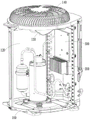
Fig. 1 is a schematic structural view of a top-outlet outdoor unit according to an embodiment of the present invention;
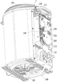
fig. 2 is one of schematic structural diagrams of the top-outlet outdoor unit according to the embodiment of the present invention with an electrical cover plate removed;
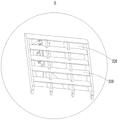
fig. 3 is a schematic view of an internal structure of a top-outlet outdoor unit according to an embodiment of the present invention;
fig. 4 is a second schematic structural view of the top-outlet outdoor unit according to the embodiment of the present invention, after the cover plate of the electrical appliance is removed, in which arrows indicate flow paths of air for dissipating heat from the electrical control box;
fig. 5 is a schematic structural diagram of an electric control box of a top-outlet outdoor unit according to an embodiment of the present invention;
FIG. 6 is an enlarged view of a portion of the structure at A in FIG. 5;
FIG. 7 is an enlarged view of a portion of the structure shown at B in FIG. 5;
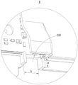
fig. 8 is a third schematic structural view of the top-outlet outdoor unit according to the embodiment of the present invention, after the cover plate of the electrical appliance is removed;
fig. 9 is an enlarged view of a portion of the structure at C in fig. 8.
Description of reference numerals:
100-a housing; 200-electric appliance cover plate; 300-an electronic control box;
110-side plate; 111-an air outlet; 120-air duct; 130-fan blades; 140-a top cover; 150-a water stop; 160-a chassis;
310-an air inlet; 320-a heat dissipation port; 330-louver; 340-high temperature components; 350-radiator.
Detailed Description
To the very poor problem of the inside heat dissipation condition of automatically controlled box that outer machine exists of top-out, at present, the heat dissipation scheme commonly used in the trade does: the cold pipe of the outdoor heat exchanger is wound into the electric control box, and when the top air outlet outdoor unit operates, the temperature of the cold pipe is lower, so that the cold pipe is utilized to cool the inside of the electric control box, and the heat dissipation condition of the inside of the electric control box is improved. Although, this heat dissipation scheme can realize the cooling to the inside of automatically controlled box, this scheme structure is complicated, assembly efficiency is low to lead to the heat dissipation cost to improve greatly.
In order to make the aforementioned objects, features and advantages of the present invention comprehensible, embodiments accompanied with figures are described in detail below. It should be understood that the specific embodiments described herein are merely illustrative of the utility model and are not intended to limit the utility model.
Fig. 1 is a schematic structural diagram of the top-outlet outdoor unit provided in this embodiment, fig. 2 is one of the schematic structural diagrams of the top-outlet outdoor unit provided in this embodiment after an electrical appliance cover plate 200 is removed, and fig. 3 is a schematic internal structural diagram of the top-outlet outdoor unit provided in this embodiment. As shown in fig. 1 to 3, the embodiment provides a top-outlet outdoor unit, including a side plate 110 for forming a casing 100, an electrical appliance cover plate 200 fixedly connected to the side plate 110, and an electrical control box 300 installed on the side plate 110, specifically, an accommodating cavity is formed between the electrical appliance cover plate 200 and the side plate 110, the electrical control box 300 is located in the accommodating cavity, and an interlayer space is formed between the electrical control box 300 and the electrical appliance cover plate 200.
Fig. 4 is a second schematic structural view (an arrow in the figure indicates a flow path of air for dissipating heat from the electrical control box 300) of the top-outlet outdoor unit provided in this embodiment after the electrical appliance cover 200 is removed. Referring to fig. 1 to fig. 3 and fig. 4, the electric control box 300 is provided with an air inlet 310 and a heat dissipation opening 320, the air inlet 310 is communicated with the air duct 120 of the top air outlet unit and the inner cavity of the electric control box 300, and the heat dissipation opening 320 is communicated with the inner cavity and the interlayer space; the side plate 110 is provided with an air outlet 111, the air outlet 111 is communicated with the interlayer space and the air duct 120, wherein the air outlet 111 is arranged near the fan blade 130 in the air duct 120, and the air inlet 310 is arranged far away from the fan blade 130.
In the operation process of the top-outlet outdoor unit, the fan blades 130 located in the air duct 120 rotate to drive the airflow in the air duct 120 to be discharged to the outside of the casing 100. In the above process, the pressure in the air duct 120 is reduced, especially the pressure at the position where the fan blades 130 are arranged in the air duct 120 is the lowest, so that the airflow in the interlayer space is discharged to the air duct 120 through the air outlet 111 and then discharged from the top opening of the top air outlet outdoor unit; when the air flow in the interlayer space is exhausted, the pressure in the interlayer space is also reduced, namely: the pressure intensity of the interlayer space is smaller than the pressure intensity of the inner cavity of the electric control box 300, so that the airflow of the inner cavity of the electric control box 300 is discharged to the interlayer space through the heat dissipation port 320; because the air flow in the inner cavity of the electronic control box 300 is exhausted to the interlayer space, the pressure of the inner cavity of the electronic control box 300 is reduced, so that the cold air flow at the lower part of the air duct 120 can enter the inner cavity of the electronic control box 300 through the air inlet 310, and the heat dissipation of the inner cavity of the electronic control box 300 is realized.
From the above analysis, it can be known that, in the operation process of the top-outlet outdoor unit, the flow path of the gas is as follows: the lower portion of the air duct 120 → the air inlet 310 → the inner cavity of the electronic control box 300 → the heat dissipating outlet 320 → the interlayer space → the air outlet 111 → the upper portion of the air duct 120 (specifically, see the arrow in fig. 4), and then, under the action of the fan blade 130, the airflow in the air duct 120 is discharged to the outside through the top opening of the top air outlet unit. The process makes the cold air in the air duct 120 enter the inner cavity of the electric control box 300, and takes away the heat in the inner cavity along with the flowing action of the air, so as to realize the heat dissipation treatment of the inner cavity environment, effectively enhance the heat dissipation effect of the inner cavity of the electric control box 300 and improve the heat dissipation condition of the electric control box 300.
In addition, the interlayer space is arranged, so that in the process that the gas continues to flow to the air outlet 111 in the interlayer space, the box wall of the electronic control box 300 is further cooled, and further heat dissipation of the inner cavity of the electronic control box 300 is realized by taking away the heat of the box wall. Simultaneously, in this in-process, the intermediate layer space can also realize the temporary storage to the air current, utilizes this part air current of keeping in to carry out lasting cooling to the box wall of automatically controlled box 300, guarantees the radiating effect. In addition, in a high-temperature environment, the interlayer space and the part of temporarily stored airflow can also play a role of heat insulation, so that the environment heat is prevented from being directly transmitted to the inner cavity of the electronic control box 300 through the electric appliance cover plate 200, the active heat dissipation of the electronic control box 300 is realized, and the passive heat insulation of the electronic control box 300 is also realized, thereby further improving the heat dissipation condition of the electronic control box 300.
It should be noted that, in this embodiment, the "air outlet 111 is disposed close to the fan blade 130 in the air duct 120, and the air inlet 310 is disposed far from the fan blade 130", where far and near indicate relative far and near, that is: the air outlet 111 is disposed closer to the fan blade 130 than the air inlet 310. With such an arrangement, a pressure difference is formed at the air outlet 111, thereby ensuring smooth flow of the gas along the flow path.
It should be noted that, in the operation process of the top-outlet air outdoor unit, the temperature of the inner cavity of the electronic control box 300 is usually above 80 ℃, and through the improvement, the temperature of the inner cavity of the electronic control box 300 can be reduced by 20-25 ℃, so that the heat dissipation condition of the electronic control box 300 is effectively improved. The air flow flows from the air duct 120 to the inner cavity of the electronic control box 300 and then flows into the interlayer space, and although the air flow entering the interlayer space has completed heat exchange with the inner cavity of the electronic control box 300, the temperature of the air flow is still lower than that of the inner cavity of the electronic control box 300, so that the air flow can perform further heat dissipation treatment on the inner cavity of the electronic control box 300 in the further flowing process of the interlayer space.
In this embodiment, the components for forming the casing 100 further include a chassis 160 and the like, which are not modified in the present invention and therefore will not be described in detail.
Referring to fig. 3, in the present embodiment, the electrical control box 300 may include a heat sink 350, the heat sink 350 faces the air duct 120 and is located in the air duct 120, wherein a portion of heat generated by electrical components in the electrical control box 300 during operation can be exhausted to the air duct 120 through the heat sink 350, and finally exhausted from a top opening of the top air outlet unit. The arrangement of the radiator 350 enhances the heat dissipation effect of the electronic control box 300, and ensures the reliability of heat dissipation of the electronic control box 300.
Referring to fig. 4, in the embodiment, the electrical control box 300 includes a box body and a box cover fixedly connected to the box body, wherein the box body of the electrical control box 300 faces the air duct 120, and the "box wall" is formed by the box cover; the air inlet 310 is arranged on the box body, and the heat radiation port 320 is arranged on the box cover; a controller is arranged in the electric control box 300.
Fig. 5 is a schematic structural diagram of an electric control box 300 of the top-outlet outdoor unit according to this embodiment, and fig. 6 is an enlarged view of a portion of a structure in fig. 5 a.
With reference to fig. 2 and fig. 5 and 6, in the present embodiment, the heat dissipation opening 320 is provided with a louver 330 having a louver structure, wherein the louver 330 extends downward relative to the direction from the inner cavity of the electronic control box 300 to the interlayer space.
Through set up this kind of louver 330 that is the shutter structure at thermovent 320, can realize effectively blockking to the outside drippage condensate water of automatically controlled box 300, prevent that it from dripping into the inner chamber of automatically controlled box 300 and make electrical components produce short circuit, corruption, played certain guard action to electrical components to the working life of automatically controlled box 300 has been prolonged.
Referring to fig. 5, in the present embodiment, the number of the heat dissipation openings 320 is two, and the two heat dissipation openings 320 are distributed. So set up, can increase the volume of airing exhaust of thermovent 320 department for through the smooth interlayer space of arranging of heat transfer air current, guaranteed the smooth and easy nature of gas flow in automatically controlled box 300 inner chamber.
Referring to fig. 4, in the present embodiment, the air outlet 111 is located above the heat dissipating opening 320. With the arrangement, the heat-exchanged hot air discharged from the heat-dissipating port 320 can be guided to the air outlet 111 by utilizing the rising principle of the hot air, so that the air flow in the inner cavity of the electronic control box 300 can smoothly flow to the interlayer space and then is discharged from the air outlet 111, and the flowing circulation of the air for dissipating heat of the electronic control box 300 is enhanced.
Referring to fig. 5, in the present embodiment, the heat dissipation opening 320 is located above the high temperature component 340 in the inner cavity of the electrical control box 300. Similarly, the arrangement can also effectively utilize the principle of hot air rising to guide the hot air flow that completes heat dissipation of the high-temperature component 340 to the heat dissipation port 320, and then smoothly discharge the hot air flow to the interlayer space, so that the subsequent cold air flow can smoothly enter the inner cavity of the electronic control box 300 from the lower part of the air duct 120, and further enhance the air flow circulation for heat dissipation of the electronic control box 300.
Note that the "high-temperature component 340" refers to: in the operation process of the top-outlet air-out external machine, the inner cavity of the electric control box 300 is in an electric element with higher working temperature, and heat generated by the work of the electric control box 300 has great influence on the temperature of the inner cavity of the electric control box 300.
Referring to fig. 5, in the embodiment, the air inlet 310 is located at the bottom of the electronic control box 300, that is, the air inlet 310 is located at the bottom of the box body.
By the arrangement, the condensed water in the air duct 120 can be prevented from splashing to the inner cavity of the electronic control box 300 from the air inlet 310, and certain protection effect is provided for electrical components in the inner cavity of the electronic control box 300.
Referring to fig. 5, in the present embodiment, the air inlet 310 is located below the high-temperature component 340 in the inner cavity of the electronic control box 300 and substantially opposite to the high-temperature component 340.
The high-temperature component 340 is arranged at the downstream of the gas flow path, so that after cold air flow at the lower part of the air duct 120 enters the inner cavity of the electric control box 300 from the air inlet 310, the high-temperature component 340 can be cooled at the first time, the heat dissipation pertinence is strong, the cold consumption in the gas flow process is reduced, the effectiveness and timeliness of heat dissipation of the high-temperature component 340 are ensured, and the heat dissipation condition of the inner cavity of the electric control box 300 is further improved.
The above "substantially relative" means: along the flow path of the air flow from the air inlet 310 to the inner cavity of the electronic control box 300, the air inlet 310 and the high-temperature component 340 are at least partially overlapped.
Fig. 7 is an enlarged view of a portion of the structure at B in fig. 5. As shown in FIG. 7, in the present embodiment, the air inlet 310 is a channel structure, specifically, the length of the channel structure is a, the width of the channel structure is b, a is greater than or equal to 10mm and less than or equal to 20mm, and b is greater than or equal to 10 mm.
By providing the air inlet 310 with a channel structure having a certain length, the air flow can be guided, so that the air flow can smoothly flow to the inner cavity of the electronic control box 300. Meanwhile, the width of the air inlet 310 is set to be not less than 10mm, so that the air inlet amount can be increased, and the smoothness of air inlet can be ensured.
In this embodiment, the number of the air inlets 310 is one, and in other embodiments, the number of the air inlets 310 may be multiple, and the multiple air inlets 310 are distributed. By providing a plurality of air inlets 310, the amount of air to be supplied can be further increased.
Fig. 8 is a third schematic structural view of the top-outlet outdoor unit provided in this embodiment with the electrical appliance cover plate 200 removed, and fig. 9 is an enlarged partial structure view of a portion C in fig. 8. As shown in fig. 8 and 9, in the present embodiment, the number of the air outlets 111 is multiple, and the air outlets 111 are distributed. So set up, can increase the air output, guarantee the air-out smooth and easy nature.
Referring to fig. 9, in the present embodiment, a water blocking member 150 is disposed inside the air duct 120, the water blocking member 150 is opposite to the air outlet 111, and the water blocking member 150 is configured to prevent water drops in the air duct 120 from entering the interlayer space through the air outlet 111.
Through setting up water blocking member 150, can realize effectively blockking of water droplet in wind channel 120, prevent that it from splashing to the intermediate layer space through air outlet 111 and causing adverse effect to automatically controlled box 300.
Preferably, the water guard 150 has a height of not less than 5 mm. By such an arrangement, the water blocking failure caused by the excessively low height of the water blocking member 150 can be avoided, and the water blocking effect is ensured.
Referring to fig. 9, in the present embodiment, specifically, the top cover 140 of the top air outlet unit has a convex edge extending toward the air duct 120, wherein the convex edge forms the water blocking member 150.
The arrangement form of integrating the water blocking member 150 into the top cover 140 is not only simple in structure, but also convenient and fast in assembly, and the purpose of automatically installing the water blocking member 150 in the air duct 120 can be achieved after the top cover 140 is assembled to the machine shell 100.
In conclusion, the top-outlet outdoor unit provided by the embodiment can effectively improve the heat dissipation condition inside the electronic control box 300, ensures the reliability of heat dissipation, and does not need to wind the cold pipe of the outdoor heat exchanger inside the electronic control box 300, so that the structure is simple, the assembly is efficient, and the cost is low.
In addition, this embodiment still provides an air conditioner, includes machine and the outer machine of above-mentioned top outlet air in the air conditioning.
Through set up above-mentioned outer machine of top-outlet air in the air conditioner, correspondingly, this air conditioner has all advantages of above-mentioned outer machine of top-outlet air, and the repeated description is no longer given here.
It should be noted that how the indoor unit of the air conditioner is connected to the top-outlet outdoor unit to ensure the normal operation of the air conditioner is the prior art well known to those skilled in the art, and this embodiment does not improve this technology, and therefore, the details are not described herein.
Although the present invention is disclosed above, the present invention is not limited thereto. Various changes and modifications may be effected therein by one skilled in the art without departing from the spirit and scope of the utility model as defined in the appended claims.
Finally, it should also be noted that, herein, relational terms such as first and second, and the like may be used solely to distinguish one entity or action from another entity or action without necessarily requiring or implying any actual such relationship or order between such entities or actions. Also, the terms "comprises," "comprising," or any other variation thereof, are intended to cover a non-exclusive inclusion, such that a process, method, article, or apparatus that comprises a list of elements does not include only those elements but may include other elements not expressly listed or inherent to such process, method, article, or apparatus. Without further limitation, an element defined by the phrase "comprising an … …" does not exclude the presence of other identical elements in a process, method, article, or apparatus that comprises the element.
In the above embodiments, the descriptions of the orientations such as "upper", "lower", "side", and the like are based on the drawings.
The previous description of the disclosed embodiments is provided to enable any person skilled in the art to make or use the present invention. Various modifications to these embodiments will be readily apparent to those skilled in the art, and the generic principles defined herein may be applied to other embodiments without departing from the spirit or scope of the utility model. Thus, the present invention is not intended to be limited to the embodiments shown herein but is to be accorded the widest scope consistent with the principles and novel features disclosed herein.
Claims (11)
1. The top-outlet outdoor unit is characterized by comprising a side plate (110) for forming a casing (100), an electric appliance cover plate (200) fixedly connected to the side plate (110) and an electric control box (300) mounted on the side plate (110), wherein a containing cavity is formed between the electric appliance cover plate (200) and the side plate (110), the electric control box (300) is located in the containing cavity, and an interlayer space is formed between the electric control box (300) and the electric appliance cover plate (200); the electric control box (300) is provided with an air inlet (310) and a heat dissipation opening (320), the air inlet (310) is communicated with an air duct (120) of the top air outlet outdoor unit and an inner cavity of the electric control box (300), and the heat dissipation opening (320) is communicated with the inner cavity and the interlayer space; an air outlet (111) is formed in the side plate (110), the air outlet (111) is communicated with the interlayer space and the air duct (120), the air outlet (111) is close to a fan blade (130) in the air duct (120), and the air inlet (310) is far away from the fan blade (130).
2. The outdoor unit of claim 1, wherein the heat dissipating port (320) is provided with a louver (330) having a louver structure, and the louver (330) extends in a downward direction with respect to a direction from the inner cavity of the electric control box (300) to the interlayer space.
3. The outdoor unit of claim 1, wherein the heat dissipation opening (320) is located above a high-temperature component (340) in the inner cavity, and/or the air outlet (111) is located above the heat dissipation opening (320).
4. The outdoor unit of claim 1, wherein a water-blocking member (150) is disposed inside the air duct (120), the water-blocking member (150) is opposite to the air outlet (111), and the water-blocking member (150) is configured to prevent water drops in the air duct (120) from entering the interlayer space through the air outlet (111).
5. The outdoor unit of claim 4, wherein the height of the water blocking member (150) is not less than 5 mm.
6. The outdoor top air outlet machine according to claim 4, characterized in that the top cover (140) of the outdoor top air outlet machine has a convex edge extending towards the air duct (120), and the convex edge forms the water blocking member (150).
7. The outdoor top air outlet machine according to any one of claims 1 to 6, wherein the number of the air inlet (310) is plural, and/or the number of the heat outlet (320) is plural, and/or the number of the air outlet (111) is plural.
8. The outdoor top air outlet machine according to any one of claims 1 to 6, wherein the air inlet (310) is located at the bottom of the electronic control box (300).
9. The outdoor unit of claim 8, wherein the air inlet (310) is located below the high-temperature component (340) of the inner cavity and substantially opposite to the high-temperature component (340).
10. The top-outlet outdoor unit of any one of claims 1 to 6, wherein the air inlet (310) is of a channel structure, the length of the channel structure is a, the width of the channel structure is b, wherein a is greater than or equal to 10mm and less than or equal to 20mm, and b is greater than or equal to 10 mm.
11. An air conditioner characterized by comprising an indoor unit of the air conditioner and the outdoor unit of any one of claims 1 to 10.
Priority Applications (1)
| Application Number | Priority Date | Filing Date | Title |
|---|---|---|---|
| CN202121878715.9U CN216080102U (en) | 2021-08-11 | 2021-08-11 | Top-outlet outdoor unit and air conditioner with same |
Applications Claiming Priority (1)
| Application Number | Priority Date | Filing Date | Title |
|---|---|---|---|
| CN202121878715.9U CN216080102U (en) | 2021-08-11 | 2021-08-11 | Top-outlet outdoor unit and air conditioner with same |
Publications (1)
| Publication Number | Publication Date |
|---|---|
| CN216080102U true CN216080102U (en) | 2022-03-18 |
Family
ID=80669348
Family Applications (1)
| Application Number | Title | Priority Date | Filing Date |
|---|---|---|---|
| CN202121878715.9U Active CN216080102U (en) | 2021-08-11 | 2021-08-11 | Top-outlet outdoor unit and air conditioner with same |
Country Status (1)
| Country | Link |
|---|---|
| CN (1) | CN216080102U (en) |
-
2021
- 2021-08-11 CN CN202121878715.9U patent/CN216080102U/en active Active
Similar Documents
| Publication | Publication Date | Title |
|---|---|---|
| CN108495538B (en) | High-power outdoor heat dissipation rack | |
| CN107166563B (en) | Window type air conditioner and electric control heat dissipation method thereof | |
| CN204612012U (en) | Air-conditioner outdoor unit and air-conditioner | |
| CN216080102U (en) | Top-outlet outdoor unit and air conditioner with same | |
| CN217979061U (en) | Air condensing units and air conditioning equipment | |
| CN111380111B (en) | Air conditioner | |
| CN115704581A (en) | Top-outlet outdoor unit and air conditioner with same | |
| CN115342445A (en) | Air condensing units and air conditioning equipment | |
| CN209084929U (en) | Radiator structure, air conditioner | |
| CN220524322U (en) | Electric control part and air conditioner with same | |
| CN111397245A (en) | Heat exchange device adopting semiconductor refrigeration and air conditioner | |
| CN214543997U (en) | Heat dissipation type automobile starting motor | |
| CN215874309U (en) | Condenser and steam cooking equipment | |
| CN217423562U (en) | Air duct machine | |
| CN112303979A (en) | Refrigerator and compressor bin heat radiation structure thereof | |
| CN215675574U (en) | Heating and ventilation air conditioner heat radiation structure | |
| CN220586568U (en) | Electric control box and air conditioner | |
| CN218103719U (en) | Shell structure, electric control device and air conditioner | |
| CN220524328U (en) | Electric control part and air conditioner | |
| CN218920254U (en) | Frequency converter, compressor and heating ventilation equipment | |
| CN214307033U (en) | Heat radiation structure of sealed lamp | |
| CN211084255U (en) | Outdoor machine of air conditioner | |
| CN109268950A (en) | Radiator structure, air conditioner | |
| CN219140925U (en) | Integrated fresh air conditioner | |
| CN212511515U (en) | Outdoor machine of air conditioner |
Legal Events
| Date | Code | Title | Description |
|---|---|---|---|
| GR01 | Patent grant | ||
| GR01 | Patent grant |