CN216076500U - A consolidate bearing structure for building engineering - Google Patents

A consolidate bearing structure for building engineering Download PDF

Info

Publication number
CN216076500U
CN216076500U CN202121948210.5U CN202121948210U CN216076500U CN 216076500 U CN216076500 U CN 216076500U CN 202121948210 U CN202121948210 U CN 202121948210U CN 216076500 U CN216076500 U CN 216076500U
Authority
CN
China
Prior art keywords
cylinder
screw
screw rod
rubber pad
bottom plate
Prior art date
Legal status (The legal status is an assumption and is not a legal conclusion. Google has not performed a legal analysis and makes no representation as to the accuracy of the status listed.)
Active
Application number
CN202121948210.5U
Other languages
Chinese (zh)
Inventor
郑鹏宇
Current Assignee (The listed assignees may be inaccurate. Google has not performed a legal analysis and makes no representation or warranty as to the accuracy of the list.)
JIANGSU ZHONGSHENG CONSTRUCTION GROUP CO LTD
Original Assignee
Individual
Priority date (The priority date is an assumption and is not a legal conclusion. Google has not performed a legal analysis and makes no representation as to the accuracy of the date listed.)
Filing date
Publication date
Application filed by Individual filed Critical Individual
Priority to CN202121948210.5U priority Critical patent/CN216076500U/en
Application granted granted Critical
Publication of CN216076500U publication Critical patent/CN216076500U/en
Active legal-status Critical Current
Anticipated expiration legal-status Critical

Links

Images

Landscapes

  • Vibration Prevention Devices (AREA)

Abstract

本实用新型公开了一种用于建筑工程的加固支撑结构,包括顶板、螺杆及底板,其特征在于,顶板的顶端设有第一橡胶垫,第一橡胶垫的底端与顶板固定连接,顶板的底端四周分别安装有第一螺丝,第一螺丝的顶端与顶板螺纹连接,顶板的底端中间部位安装有螺杆,螺杆的顶端与顶板固定连接,螺杆的底端安装有圆柱,圆杆的内部安装该有圆孔,圆柱的内部与螺杆活动连接,圆柱与螺杆的相交处安装有调节螺套,调节螺套的内壁安装有螺纹,调节螺套的内部底端安装有滚珠,圆柱的顶端四周分别安装有凹槽,圆柱中间部位的一侧安装有螺栓,螺栓的一端与圆柱螺纹连接,圆柱的底端安装有底座,底座的顶端中间部位与圆柱固定连接。本实用新型结构简单,操作方便。
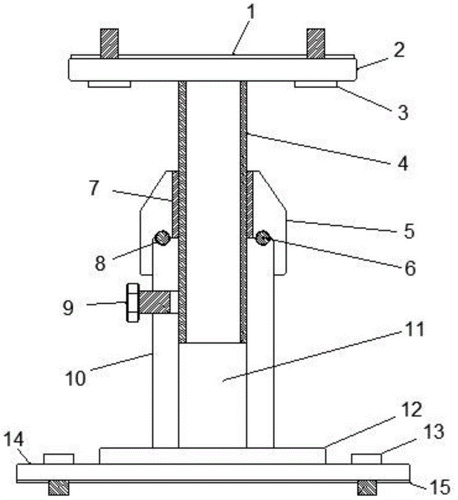
Figure 202121948210

The utility model discloses a reinforcement support structure for construction engineering, comprising a top plate, a screw rod and a bottom plate. The utility model is characterized in that a first rubber pad is arranged at the top of the top plate, and the bottom end of the first rubber pad is fixedly connected with the top plate. A first screw is installed around the bottom end of the screw rod, the top of the first screw is threadedly connected with the top plate, a screw rod is installed in the middle of the bottom end of the top plate, the top of the screw rod is fixedly connected with the top plate, the bottom end of the screw rod is installed with a cylinder, and the There is a circular hole in the internal installation, the inside of the cylinder is movably connected with the screw, the intersection of the cylinder and the screw is installed with an adjusting screw sleeve, the inner wall of the adjusting screw sleeve is installed with a thread, the inner bottom end of the adjusting screw sleeve is installed with a ball, and the top of the cylinder is installed Grooves are installed all around, a bolt is installed on one side of the middle part of the cylinder, one end of the bolt is connected with the cylinder thread, the bottom end of the cylinder is installed with a base, and the middle part of the top of the base is fixedly connected with the cylinder. The utility model has simple structure and convenient operation.

Figure 202121948210

Description

A consolidate bearing structure for building engineering
Technical Field
The utility model relates to the technical field of constructional engineering, in particular to a reinforced support structure for constructional engineering.
Background
The building engineering is a part of the construction engineering, and refers to an engineering entity formed by the construction of various house buildings and their auxiliary facilities and the installation activities of lines, pipelines and equipment matched with the house buildings, including factory buildings, theaters, hotels, shops, schools, hospitals, houses and the like, and meets the requirements of people on production, living, study, public activities and the like, so the building engineering supporting device is particularly important in the development of the modern society.
SUMMERY OF THE UTILITY MODEL
The present invention is directed to a reinforced support structure for construction engineering to solve the problems set forth in the background art.
In order to achieve the purpose, the utility model provides the following technical scheme:
a reinforced supporting structure for constructional engineering comprises a top plate, a screw rod and a bottom plate, and is characterized in that a first rubber pad is arranged at the top end of the top plate, the bottom end of the first rubber pad is fixedly connected with the top plate, first screws are respectively arranged on the periphery of the bottom end of the top plate, the top end of each first screw is in threaded connection with the top plate, the screw rod is arranged in the middle of the bottom end of the top plate, the top end of the screw rod is fixedly connected with the top plate, a cylinder is arranged at the bottom end of the screw rod, a round hole is arranged in the cylinder, the interior of the cylinder is movably connected with the screw rod, an adjusting screw sleeve is arranged at the intersection of the cylinder and the screw rod, threads are arranged on the inner wall of the adjusting screw sleeve, balls are arranged at the bottom end of the interior of the adjusting screw sleeve, grooves are respectively arranged on the periphery of the top end of the cylinder, and a bolt is arranged on one side of the middle of the cylinder, the one end of bolt with cylinder threaded connection, the base is installed to the cylindrical bottom, the top middle part of base with cylinder fixed connection, the bottom plate is installed to the bottom of base, the top middle part of bottom plate with base fixed connection, install the second screw around the bottom plate respectively, the bottom of second screw with bottom plate threaded connection, the second rubber pad is installed to the bottom of bottom plate, the top of second rubber pad with bottom plate fixed connection.
As a further aspect of the present invention, a bottom end of the ball is fitted into the inside of the groove.
As a further scheme of the utility model, the inner wall thread of the adjusting screw sleeve is in threaded connection with the screw rod.
As a further scheme of the utility model, the bottom end of the interior of the adjusting screw sleeve is provided with a notch, and the notch is in sliding connection with the top end of the ball.
As a further scheme of the utility model, one end of the bolt is provided with a wear-resistant rubber pad.
Compared with the prior art, the utility model has the beneficial effects that:
the adjusting screw sleeve can be screwed down to rotate outside the working personnel, the screw rod can be driven to extend by the rotation of the adjusting screw sleeve, the height of the whole device can be conveniently adjusted, the adjusting screw sleeve can be used for supporting structures in various constructional engineering, fine height adjustment can be simultaneously carried out, and the adjusting screw sleeve is simple in structure and convenient to operate.
Drawings
In order to more clearly illustrate the technical solutions of the embodiments of the present invention, the drawings used in the description of the embodiments will be briefly introduced below, and it is obvious that the drawings in the following description are only some embodiments of the present invention, and it is obvious for those skilled in the art that other drawings can be obtained according to the drawings without creative efforts.
Fig. 1 is a schematic overall cross-sectional view of a reinforcing support structure for construction work according to the utility model;
fig. 2 is an overall top view schematic diagram of a reinforcing support structure for construction work according to the utility model.
In the drawings, the components represented by the respective reference numerals are listed below:
1. a first rubber pad; 2. a top plate; 3. a first screw; 4. a screw; 5. adjusting a threaded sleeve; 6. a ball bearing; 7. a thread; 8. a groove; 9. a bolt; 10. a cylinder; 11. a circular hole; 12. a base; 13. a second screw; 14. a base plate; 15. and a second rubber pad.
Detailed Description
The technical solutions in the embodiments of the present invention will be clearly and completely described below with reference to the drawings in the embodiments of the present invention, and it is obvious that the described embodiments are only a part of the embodiments of the present invention, and not all of the embodiments. All other embodiments, which can be derived by a person skilled in the art from the embodiments given herein without making any creative effort, shall fall within the protection scope of the present invention.
In the description of the present invention, it should be noted that the terms "top", "bottom", "one side", "the other side", "front", "back", "middle part", "inside", "top", "bottom", etc. indicate orientations or positional relationships based on the orientations or positional relationships shown in the drawings, and are only for convenience of describing the present invention and simplifying the description, but do not indicate or imply that the referred device or element must have a specific orientation, be constructed in a specific orientation, and be operated, and thus, should not be construed as limiting the present invention; the terms "first," "second," and "third" are used for descriptive purposes only and are not to be construed as indicating or implying relative importance; furthermore, unless expressly stated or limited otherwise, the terms "mounted," "connected," and "connected" are to be construed broadly, as they may be fixedly connected, detachably connected, or integrally connected, for example; can be mechanically or electrically connected; they may be connected directly or indirectly through intervening media, or they may be interconnected between two elements. The specific meanings of the above terms in the present invention can be understood in specific cases to those skilled in the art.
Referring to fig. 1-2, a reinforcing and supporting structure for building engineering according to an embodiment of the present invention includes a top plate 2, a screw rod 4 and a bottom plate 14, and is characterized in that a first rubber pad 1 is disposed at a top end of the top plate 2, a bottom end of the first rubber pad 1 is fixedly connected to the top plate 2, first screws 3 are respectively mounted around a bottom end of the top plate 2, a top end of each first screw 3 is in threaded connection with the top plate 2, the screw rod 4 is mounted in a middle portion of a bottom end of the top plate 2, a top end of each screw rod 4 is fixedly connected to the top plate 2, a cylinder 10 is mounted at a bottom end of each screw rod 4, a circular hole 11 is mounted inside each cylinder 10, the inside of each cylinder 10 is movably connected to the screw rod 4, an adjusting screw sleeve 5 is mounted at an intersection of the cylinder 10 and the screw rod 4, and a thread 7 is mounted on an inner wall of the adjusting screw sleeve 5, ball 6 is installed to the inside bottom of adjusting swivel nut 5, install recess 8 around the top of cylinder 10 respectively, bolt 9 is installed to one side of cylinder 10 middle part, bolt 9's one end with cylinder 10 threaded connection, base 12 is installed to the bottom of cylinder 10, base 12's top middle part with cylinder 10 fixed connection, bottom plate 14 is installed to base 12's bottom, bottom plate 14's top middle part with base 12 fixed connection, bottom plate 14 install second screw 13 around respectively, the bottom of second screw 13 with bottom plate 14 threaded connection, second rubber pad 15 is installed to bottom plate 14's bottom, the top of second rubber pad 15 with bottom plate 14 fixed connection.
According to the scheme of the utility model, the bottom end of the ball 6 is embedded in the groove 8, the inner wall thread 7 of the adjusting screw sleeve 5 is in threaded connection with the screw rod 4, the bottom end of the inner part of the adjusting screw sleeve 5 is provided with a notch, the notch is in sliding connection with the top end of the ball 6, and one end of the bolt 9 is provided with a wear-resistant rubber pad.
The working principle is as follows: roof 1 and the bottom of building engineering equipment pass through first screw 3 fixed connection, pass through second screw 13 fixed connection between bottom plate 14 and the top of building engineering equipment, and the staff twists according to the required numerical value of building engineering and moves regulation swivel nut 5, lets screw rod 4 can reciprocate to this distance between the control building engineering structure, twists bolt 9 at last and fixes.
In summary, the following steps: the adjusting screw sleeve can be screwed down to rotate outside the working personnel, the screw rod can be driven to extend by the rotation of the adjusting screw sleeve, the height of the whole device can be conveniently adjusted, the adjusting screw sleeve can be used for supporting structures in various constructional engineering, fine height adjustment can be simultaneously carried out, and the adjusting screw sleeve is simple in structure and convenient to operate.
The preferred embodiments of the utility model disclosed above are intended to be illustrative only. The preferred embodiments are not intended to be exhaustive or to limit the utility model to the precise embodiments disclosed. Obviously, many modifications and variations are possible in light of the above teaching.
The embodiments were chosen and described in order to best explain the principles of the utility model and the practical application, to thereby enable others skilled in the art to best utilize the utility model. The utility model is limited only by the claims and their full scope and equivalents.

Claims (5)

1. The utility model provides a consolidate bearing structure for building engineering, includes roof (2), screw rod (4) and bottom plate (14), its characterized in that, the top of roof (2) is equipped with first rubber pad (1), the bottom of first rubber pad (1) with roof (2) fixed connection, first screw (3) are installed respectively all around the bottom of roof (2), the top of first screw (3) with roof (2) threaded connection, screw rod (4) are installed to the bottom middle part of roof (2), the top of screw rod (4) and roof (2) fixed connection, cylinder (10) are installed to the bottom of screw rod (4), the internally mounted of cylinder (10) has round hole (11), the inside of cylinder (10) with screw rod (4) swing joint, regulation swivel nut (5) are installed to the crossing department of cylinder (10) with screw rod (4), the inner wall of the adjusting screw sleeve (5) is provided with a thread (7), the inner bottom of the adjusting screw sleeve (5) is provided with a ball (6), the top of the cylinder (10) is provided with a groove (8) all around, one side of the middle part of the cylinder (10) is provided with a bolt (9), one end of the bolt (9) is in threaded connection with the cylinder (10), the bottom of the cylinder (10) is provided with a base (12), the middle part of the top of the base (12) is fixedly connected with the cylinder (10), the bottom of the base (12) is provided with a bottom plate (14), the middle part of the top of the bottom plate (14) is fixedly connected with the base (12), the periphery of the bottom plate (14) is provided with a second screw (13), the bottom of the second screw (13) is in threaded connection with the bottom plate (14), the bottom of the bottom plate (14) is provided with a second rubber pad (15), the top end of the second rubber pad (15) is fixedly connected with the bottom plate (14).
2. A reinforced support structure for building engineering according to claim 1, characterized in that the bottom ends of the balls (6) are engaged with the inside of the grooves (8).
3. A reinforced support structure for building engineering according to claim 1, characterized in that the inner wall thread (7) of the adjusting screw sleeve (5) is in threaded connection with the screw (4).
4. A reinforced support structure for building engineering according to claim 1, characterized in that the inner bottom end of the adjusting screw sleeve (5) is provided with a notch, which is slidingly connected with the top end of the ball (6).
5. A reinforced support structure for building engineering according to claim 1, characterized in that one end of the bolt (9) is fitted with a wear-resistant rubber pad.
CN202121948210.5U 2021-08-19 2021-08-19 A consolidate bearing structure for building engineering Active CN216076500U (en)

Priority Applications (1)

Application Number Priority Date Filing Date Title
CN202121948210.5U CN216076500U (en) 2021-08-19 2021-08-19 A consolidate bearing structure for building engineering

Applications Claiming Priority (1)

Application Number Priority Date Filing Date Title
CN202121948210.5U CN216076500U (en) 2021-08-19 2021-08-19 A consolidate bearing structure for building engineering

Publications (1)

Publication Number Publication Date
CN216076500U true CN216076500U (en) 2022-03-18

Family

ID=80670550

Family Applications (1)

Application Number Title Priority Date Filing Date
CN202121948210.5U Active CN216076500U (en) 2021-08-19 2021-08-19 A consolidate bearing structure for building engineering

Country Status (1)

Country Link
CN (1) CN216076500U (en)

Similar Documents

Publication Publication Date Title
WO2020143222A1 (en) Fabricated suspended ceiling structure and installation method therefor
CN213539814U (en) A consolidate bearing structure for building engineering
CN110307220A (en) A kind of anti-object tilt cotton rope fastening-type positioning device
CN110107076A (en) A kind of high building outdoor work Multifunctional fastening device
CN210597409U (en) Foundation detection equipment with tripod horizontal support frame for building construction
CN216348557U (en) Building horizontal angle detection equipment with telescopic detection function
CN213774393U (en) Safe anti-falling device for building construction
CN212896370U (en) Foundation pit support structure
CN212616775U (en) Pipeline fixing device on scaffold is built in room
CN213067573U (en) Building engineering cost is with supplementary mapping instrument
CN222350270U (en) A clamping device for construction
CN211146194U (en) Illumination angle adjusting mechanism for building information model
CN222142466U (en) A surveying instrument for engineering surveying
CN109898832B (en) A fixed bracket for house construction engineering
CN222782364U (en) A tower crane wall-mounted operating platform
CN211399185U (en) Construction engineering project management detection ruler
CN212743370U (en) Building engineering frame post template reinforcing apparatus
CN210067524U (en) A consolidate bearing structure for building engineering
CN222253146U (en) Template fixing assembly for building engineering construction
CN218643636U (en) A new type of anti-seismic structure used in construction engineering
CN209692935U (en) A kind of architectural engineering monitoring device being easily installed
CN218219547U (en) An architectural surveying table that is easy to adjust the angle
CN218780014U (en) A kind of anti-seismic reinforced structure of house building
CN223952206U (en) Adjustable cantilever frame
CN222936458U (en) Inclined support mounting structure of top unconstrained slat

Legal Events

Date Code Title Description
GR01 Patent grant
GR01 Patent grant
TR01 Transfer of patent right

Effective date of registration: 20241021

Address after: Room 1703, Unit 2, Building 4, No. 19 Yikang Street, Jianye District, Nanjing City, Jiangsu Province 210000

Patentee after: Gu He

Country or region after: China

Patentee after: Jiang Zisheng

Address before: 130 Changjiang Road, Nangang District, Harbin, Heilongjiang Province

Patentee before: Zheng Pengyu

Country or region before: China

TR01 Transfer of patent right

Effective date of registration: 20241226

Address after: 3rd Floor, Jinhe Building, No. 3 Xiangshan Road, Pukou District, Nanjing City, Jiangsu Province 210000

Patentee after: Jiangsu Zhongsheng Construction Group Co.,Ltd.

Country or region after: China

Address before: Room 1703, Unit 2, Building 4, No. 19 Yikang Street, Jianye District, Nanjing City, Jiangsu Province 210000

Patentee before: Gu He

Country or region before: China

Patentee before: Jiang Zisheng