CN216076180U - Scaffold for house repair - Google Patents
Scaffold for house repair Download PDFInfo
- Publication number
- CN216076180U CN216076180U CN202121859704.6U CN202121859704U CN216076180U CN 216076180 U CN216076180 U CN 216076180U CN 202121859704 U CN202121859704 U CN 202121859704U CN 216076180 U CN216076180 U CN 216076180U
- Authority
- CN
- China
- Prior art keywords
- scaffold
- fixedly connected
- movable
- controller
- house
- Prior art date
- Legal status (The legal status is an assumption and is not a legal conclusion. Google has not performed a legal analysis and makes no representation as to the accuracy of the status listed.)
- Expired - Fee Related
Links
Images



Landscapes
- Movable Scaffolding (AREA)
Abstract
The utility model discloses a scaffold for house maintenance, and relates to the technical field of scaffold equipment. The movable wheel can be pushed out from the inside of the bottom frame until the movable wheel is contacted with the ground through the mutual matching among the arranged hydraulic rod, the movable plate, the sliding block and the sliding groove, at the moment, the device can conveniently move, when the movement of the device needs to be limited, the movable plate is driven to move upwards through the arranged hydraulic rod, the movable wheel is further driven to move upwards until the movable wheel is separated from the ground, at the moment, the movement of the device is limited, the contact area with the ground can be increased under the mutual matching of the bottom frame, the stability of the device in the use process is further ensured, and the tool box can be driven to move in the vertical direction through the mutual matching among the arranged motor, the winding wheel, the rope, the bolting block, the movable block and the concave sliding rod.
Description
Technical Field
The utility model relates to a scaffold for repairing, in particular to a scaffold for repairing a house.
Background
At present, no matter building construction, bridge construction, billboard installation or indoor and outdoor decoration need to work in high altitude, a scaffold is various supports erected for constructors to live up and down or maintain peripheral safety nets and install components in high altitude on the modern building construction site, and the scaffold always provides very convenient conditions for the building industry.
The existing scaffold for repairing has some defects and shortcomings when in use, and the places needing improvement are as follows:
the existing scaffold for house repair does not have the function of automatically conveying repair tools in the using process, repair personnel need to take the required repair tools through continuous scaffold mounting and demounting, the taking process is troublesome, meanwhile, certain potential safety hazards can be brought to the self safety of the repair personnel in the process that the repair personnel continuously mount and demount the scaffold, and the existing scaffold is not convenient to move in the using process.
SUMMERY OF THE UTILITY MODEL
The utility model aims to provide a scaffold for house repair, which solves the problems that the existing scaffold for house repair provided in the background technology does not have the function of automatically conveying repair tools in the using process, repair personnel need to continuously get the required repair tools up and down through the scaffold, the taking process is troublesome, meanwhile, certain potential safety hazards are brought to the self safety of the repair personnel in the process of continuously getting up and down the scaffold, and the existing scaffold is inconvenient to move in the using process.
In order to achieve the purpose, the utility model provides the following technical scheme: the utility model provides a scaffold frame for house repair, includes the scaffold frame main part, scaffold frame main part upper surface right side fixedly connected with motor, fixedly connected with winding wheel on the motor output shaft, the one end swing joint of winding wheel and rope, the other end of rope passes pulley and bolt piece swing joint, bolt piece fixed connection is on the tool holder left surface, the equal fixedly connected with movable block in both sides, two around the tool holder left end the movable block respectively with two spill slide bar swing joint.
According to the optimal technical scheme, the upper ends of the two concave sliding rods are fixedly connected to the right side face of the upper end of the scaffold main body, and the lower ends of the two concave sliding rods are fixedly connected to the right side face of the bottom frame.
As a preferred technical solution of the present invention, the bottom frame is fixedly connected to a lower side of the scaffold main body, hydraulic rods are fixedly connected to both left and right sides of an upper surface inside the bottom frame, and lower ends of the two hydraulic rods are respectively and fixedly connected to central positions of upper surfaces of the two movable plates.
According to a preferred technical scheme of the utility model, the front end and the rear end of each of the two movable plates are fixedly connected with a sliding block, every two sliding blocks are movably connected in two sliding grooves formed in the front side face and the rear side face of the bottom frame in a group, and the front end and the rear end of the lower surface of each of the two movable plates are fixedly connected with movable wheels.
According to a preferable technical scheme, the pulley is movably connected to the right side of the upper end of the scaffold main body through a pulley seat, a climbing frame is fixedly connected to the middle position of the front end of the scaffold main body, and the uppermost end of the climbing frame and the uppermost end of the scaffold main body are located on the same horizontal line.
As a preferable technical scheme of the present invention, a guard rail is fixedly connected to an upper surface of the scaffold body, a space is left on a front side of the guard rail, a second controller is arranged on a right side of a front end of the guard rail, an output end of the second controller is electrically connected to an input end of a motor, and the motor is a forward and reverse rotation motor with a model number of WS-52ZYT 89-R.
As a preferable technical scheme of the utility model, a first controller is arranged on the left side of the upper surface of the bottom frame, a storage battery is arranged on the right side of the upper surface of the bottom frame, an output end of the storage battery is electrically connected with input ends of the first controller and the second controller respectively, and an output end of the first controller is electrically connected with an input end of a hydraulic rod.
Compared with the prior art, the utility model has the beneficial effects that:
the movable wheel can be pushed out from the inside of the bottom frame until the movable wheel is contacted with the ground through the mutual matching of the arranged hydraulic rod, the movable plate, the sliding block and the sliding groove, at the moment, the device can be conveniently moved, when the movement of the device needs to be limited, the movable plate is driven to move upwards through the arranged hydraulic rod, the movable wheel is further driven to move upwards until the movable wheel is separated from the ground, at the moment, the movement of the device is limited, the contact area with the ground can be increased under the mutual matching of the bottom frame, the stability of the device in the using process is further ensured, the tool box can be driven to move in the vertical direction through the mutual matching of the arranged motor, the winding wheel, the rope, the bolting block, the movable block and the concave sliding rod, the repairing tool which needs to be conveniently conveyed to the upper part of the device can be conveniently conveyed, and repairing tools which need to be taken by a repairing person to climb a scaffold up and down to be effectively avoided, so that the repairing person needs to take repairing tools up and down to safely self Causing a certain influence.
Drawings
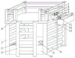
FIG. 1 is a schematic perspective view of the present invention;
FIG. 2 is a schematic view of a bottom frame of the present invention showing a three-dimensional enlarged structure of a front view section;
FIG. 3 is a left side perspective view of the tool box of the present invention;
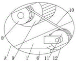
FIG. 4 is an enlarged schematic view of the structure at A of the present invention;
fig. 5 is an enlarged schematic view of the structure at B of the present invention.
In the figure: the scaffold comprises a scaffold main body 1, a controller I2, a climbing frame 3, a protective guard 4, a storage battery 5, a concave sliding rod 6, a controller II 7, a winding wheel 8, a motor 9, a rope 10, a pulley 11, a tool box 12, a movable block 13, a bottom frame 14, a movable wheel 15, a hydraulic rod 16, a movable wheel 17, a sliding chute 18, a sliding block 19 and a bolt-connecting block 20.
Detailed Description
The technical solutions in the embodiments of the present invention will be clearly and completely described below with reference to the drawings in the embodiments of the present invention, and it is obvious that the described embodiments are only a part of the embodiments of the present invention, and not all of the embodiments. All other embodiments, which can be derived by a person skilled in the art from the embodiments given herein without making any creative effort, shall fall within the protection scope of the present invention.
As shown in fig. 1 to 5, the present invention provides a technical solution: a scaffold for house maintenance comprises a scaffold body 1, a motor 9 is fixedly connected to the right side of the upper surface of the scaffold body 1, a winding wheel 8 is fixedly connected to an output shaft of the motor 9, the winding wheel 8 is movably connected with one end of a rope 10, the other end of the rope 10 penetrates through a pulley 11 to be movably connected with a bolting block 20, the bolting block 20 is fixedly connected to the left side surface of a tool box 12, movable blocks 13 are fixedly connected to the front side and the rear side of the left end of the tool box 12, the two movable blocks 13 are respectively movably connected with two concave slide bars 6, the movement direction of the tool box 12 can be limited through the mutual matching of the arranged movable blocks 13 and the concave slide bars 6, the winding wheel 8 can be driven to rotate through the rotation of the output shaft of the motor 9, the tool box 12 can be driven to move in the up-down direction through the rotation of the winding wheel 8 under the mutual matching of the arranged rope 10, the pulley 11 and the bolting block 20, therefore, the required repairing tool can be conveniently conveyed to the upper end of the scaffold main body 1, the problem that repairing personnel need to climb up and down the scaffold main body 1 continuously to take the repairing tool is avoided, the safety of the repairing personnel is improved to a certain degree, the upper ends of two concave slide bars 6 are fixedly connected to the right side surface of the upper end of the scaffold main body 1, the lower ends of the two concave slide bars 6 are fixedly connected to the right side surface of the bottom frame 14, the bottom frame 14 is fixedly connected to the lower side of the scaffold main body 1, the left side and the right side of the upper surface in the bottom frame 14 are fixedly connected with hydraulic rods 16, the lower ends of the two hydraulic rods 16 are respectively fixedly connected to the central positions of the upper surfaces of the two movable plates 15, the front end and the rear end of the two movable plates 15 are respectively fixedly connected with sliders 19, a group of the four sliders 19 are respectively movably connected to the insides of two chutes 18 which are respectively arranged on the front side surface and the rear side surface of the bottom frame 14, the front end and the rear end of the lower surfaces of the two moving plates 15 are fixedly connected with moving wheels 17, the moving direction of the moving plates 15 can be limited by the mutual matching between the arranged slide blocks 19 and the chutes 18, the moving plates 15 can be pushed to move downwards by starting the hydraulic rods 16, the arranged moving wheels 17 can be pushed out from the inside of the bottom frame 14 until being contacted with the ground, at the moment, the device can conveniently move, the pulleys 11 are movably connected to the right side of the upper end of the scaffold body 1 through the arranged pulley seats, the middle position of the front end of the scaffold body 1 is fixedly connected with a climbing frame 3, the uppermost end of the climbing frame 3 and the uppermost end of the scaffold body 1 are positioned on the same horizontal line, maintenance personnel can conveniently repair the scaffold body 1 by standing on the upper end of the scaffold body 1 through the arranged climbing frame 3, and the protective guard 4 is fixedly connected on the upper surface of the scaffold body 1, a space is reserved on the front side of the protective guard 4, the protective guard 4 can play a certain protection role on the self safety of a repairing person in the house repairing process of the repairing person, the second controller 7 is arranged on the right side of the front end of the protective guard 4, the output end of the second controller 7 is electrically connected with the input end of the motor 9, the first controller 2 is arranged on the left side of the upper surface of the bottom frame 14, the storage battery 5 is arranged on the right side of the upper surface of the bottom frame 14, the output end of the storage battery 5 is electrically connected with the first controller 2 and the input end of the second controller 7 respectively, and the output end of the first controller 2 is electrically connected with the input end of the hydraulic rod 16.
The method comprises the following operation steps:
when the device needs to be moved, the two hydraulic rods 16 are started through the first controller 2, the two hydraulic rods 16 respectively push the two moving plates 15 to move downwards until the four moving wheels 17 are all pushed out of the bottom frame 14 and are all contacted with the ground, at the moment, the device can be conveniently moved, when the device does not need to be moved, the two moving plates 15 are respectively driven to move upwards through the two hydraulic rods 16, the moving wheels 17 are further driven to move upwards and are separated from the ground, at the moment, the movement of the device is limited, when a maintenance worker repairs houses, firstly, a maintenance tool is placed in the tool box 12, then the maintenance worker stands to the upper end of the scaffold main body 1 through the arranged climbing frame 3, then, the motor 9 is started through the second controller 7, the motor 9 drives the winding wheel 8 to rotate through the rotation of an output shaft of the motor 9, and the tool box 12 can be driven to move upwards under the mutual cooperation of the arranged rope 10, the pulley 11 and the bolting block 20, and at the moment, a repairing person can conveniently take repairing tools from the inside of the tool box 12 to repair the house.
In the description of the present invention, it is to be understood that the indicated orientations or positional relationships are based on the orientations or positional relationships shown in the drawings and are only for convenience in describing the present invention and simplifying the description, but are not intended to indicate or imply that the indicated devices or elements must have a particular orientation, be constructed and operated in a particular orientation, and are not to be construed as limiting the present invention.
In the present invention, unless otherwise explicitly specified or limited, for example, it may be fixedly attached, detachably attached, or integrated; can be mechanically or electrically connected; the terms may be directly connected or indirectly connected through an intermediate, and may be communication between two elements or interaction relationship between two elements, unless otherwise specifically limited, and the specific meaning of the terms in the present invention will be understood by those skilled in the art according to specific situations.
Although embodiments of the present invention have been shown and described, it will be appreciated by those skilled in the art that changes, modifications, substitutions and alterations can be made in these embodiments without departing from the principles and spirit of the utility model, the scope of which is defined in the appended claims and their equivalents.
Claims (7)
1. A scaffold for house repair, comprising a scaffold main body (1), characterized in that: scaffold frame main part (1) upper surface right side fixedly connected with motor (9), fixedly connected with winding wheel (8) on motor (9) output shaft, winding wheel (8) and the one end swing joint of rope (10), the other end of rope (10) passes pulley (11) and bolt piece (20) swing joint, bolt piece (20) fixed connection is on tool holder (12) left surface, the equal fixedly connected with movable block (13) in both sides around tool holder (12) left end, two movable block (13) respectively with two spill slide bar (6) swing joint.
2. The scaffold for house renovation according to claim 1, wherein: the upper ends of the two concave sliding rods (6) are fixedly connected to the right side face of the upper end of the scaffold main body (1), and the lower ends of the two concave sliding rods (6) are fixedly connected to the right side face of the bottom frame (14).
3. The scaffold for house renovation according to claim 2, wherein: underframe (14) fixed connection is at the downside of scaffold frame main part (1), the equal fixedly connected with hydraulic stem (16) of underframe (14) inside upper surface left and right sides, two the lower extreme of hydraulic stem (16) is fixed connection respectively and puts the department at two movable plate (15) upper surface central points.
4. The scaffold for house renovation according to claim 3, wherein: the front end and the rear end of each of the two movable plates (15) are fixedly connected with sliding blocks (19), every two sliding blocks (19) are movably connected into two sliding grooves (18) which are formed in the front side face and the rear side face of the bottom frame (14) respectively in a group, and the front end and the rear end of the lower surface of each of the two movable plates (15) are fixedly connected with movable wheels (17).
5. The scaffold for house renovation according to claim 1, wherein: pulley (11) are on scaffold frame main part (1) upper end right side through the pulley holder swing joint that sets up, fixedly connected with climbing frame (3) on scaffold frame main part (1) front end intermediate position, the top of climbing frame (3) is in on the same water flat line with scaffold frame main part (1) top.
6. The scaffold for house renovation according to claim 5, wherein: the scaffold is characterized in that a protective guard (4) is fixedly connected to the upper surface of the scaffold main body (1), a space is reserved on the front side of the protective guard (4), a second controller (7) is arranged on the right side of the front end of the protective guard (4), and the output end of the second controller (7) is electrically connected with the input end of a motor (9).
7. The scaffold for house renovation according to claim 2, wherein: underframe (14) upper surface left side is provided with controller (2), underframe (14) upper surface right side is provided with battery (5), the output of battery (5) is connected with the input electricity of controller (2) and controller (7) respectively, the output of controller (2) is connected with the input electricity of hydraulic stem (16).
Priority Applications (1)
| Application Number | Priority Date | Filing Date | Title |
|---|---|---|---|
| CN202121859704.6U CN216076180U (en) | 2021-08-10 | 2021-08-10 | Scaffold for house repair |
Applications Claiming Priority (1)
| Application Number | Priority Date | Filing Date | Title |
|---|---|---|---|
| CN202121859704.6U CN216076180U (en) | 2021-08-10 | 2021-08-10 | Scaffold for house repair |
Publications (1)
| Publication Number | Publication Date |
|---|---|
| CN216076180U true CN216076180U (en) | 2022-03-18 |
Family
ID=80669186
Family Applications (1)
| Application Number | Title | Priority Date | Filing Date |
|---|---|---|---|
| CN202121859704.6U Expired - Fee Related CN216076180U (en) | 2021-08-10 | 2021-08-10 | Scaffold for house repair |
Country Status (1)
| Country | Link |
|---|---|
| CN (1) | CN216076180U (en) |
-
2021
- 2021-08-10 CN CN202121859704.6U patent/CN216076180U/en not_active Expired - Fee Related
Similar Documents
| Publication | Publication Date | Title |
|---|---|---|
| CN202644959U (en) | Attached elevating scaffold based on lead screw and screw transmission | |
| CN201730624U (en) | Construction work vehicle for subway region tunnel | |
| CN113148535B (en) | Electric power is with overhauing device | |
| CN222797003U (en) | A safety protection device for roof photovoltaic power station construction | |
| CN221609893U (en) | Crawling ladder for harbour site | |
| CN108824934B (en) | Multi-functional electric power communication tower convenient to maintenance | |
| CN214245396U (en) | Bridge construction safety support bracket | |
| CN107196234A (en) | A kind of repair method of power equipment | |
| CN219792430U (en) | An auxiliary lifting platform for power operation and maintenance | |
| CN217516545U (en) | Maintenance cage for double-beam bridge crane | |
| CN214360123U (en) | Small-size lift is used in engineering construction | |
| CN219156459U (en) | Network communication construction device of ascending a height | |
| CN209922843U (en) | Rain shielding device for crawler-type overhead working truck | |
| CN223534826U (en) | A power grid construction aerial work platform | |
| CN219751849U (en) | Lifting type maintenance platform device | |
| CN213683138U (en) | Assembly type structure bearing structure for interior decoration engineering | |
| CN218176574U (en) | Scaffold frame for interior decoration with platform is put to work piece | |
| CN213143825U (en) | A large-scale hanging basket stabilization device for nuclear power plant construction | |
| CN222162122U (en) | Roofing repair operation device | |
| CN220365277U (en) | Device for assisting in translation of hanging basket | |
| CN218343513U (en) | Urban rail vehicle door overhauling platform | |
| CN215331322U (en) | Civil construction is indoor with scaffold | |
| CN217756798U (en) | Power station boiler platform supporting beam | |
| CN220886935U (en) | Auxiliary tool for subway power supply maintenance | |
| CN217452708U (en) | Triaxial gantry welding device |
Legal Events
| Date | Code | Title | Description |
|---|---|---|---|
| GR01 | Patent grant | ||
| GR01 | Patent grant | ||
| CF01 | Termination of patent right due to non-payment of annual fee | ||
| CF01 | Termination of patent right due to non-payment of annual fee |
Granted publication date: 20220318 |