Release film unreeling machine capable of adjusting tension
Technical Field
The utility model relates to the technical field of release film unreeling machines, in particular to a release film unreeling machine capable of adjusting tension.
Background
The release film has large tension due to the characteristics of the material in the unreeling process, is dangerous when unreeling and has poor unreeling effect.
Wherein the application number of 202020303699 in the prior art proposes a tension adjusting device of a PET release film unwinding mechanism, which comprises an unwinding base, a driving case is arranged on the upper side of the unreeling base, one end of the driving case is connected with a driving shaft in a transmission way, one end of the driving shaft is provided with a unreeling shaft lever, the upper side of the other end of the unreeling base is provided with a vertical plate, a side baffle is arranged on one side of the vertical plate, a tension adjusting hole is arranged in the side baffle, a screw rod is arranged in the tension adjusting hole, the screw rod is in threaded connection with a screw rod pair, one side of the screw rod pair is provided with a tension pressure rod, the outer side of the tension pressure rod is sleeved with a pressure adjusting roller in a rolling way, the tension adjusting device of the PET release film unreeling mechanism is provided with a tension adjusting device, the tension pressure rod arranged on one side of the side baffle in a sliding mode can be pressed on the outer side of the unreeling shaft rod, so that the unreeling shaft rod is always in a tensioning state after being wound with the release film.
It unreels the in-process, and release film rolls up less and less, and its effect of adjusting tension can worsen, can not satisfy and unreel the demand.
SUMMERY OF THE UTILITY MODEL
The utility model aims to overcome the defects in the prior art, and provides a release film unreeling machine capable of adjusting tension, which can continuously extrude a reel provided with a release film in the unreeling process, realize the tension control of the reel, ensure better unreeling effect and effectively solve the problems in the background art.
In order to achieve the purpose, the utility model provides the following technical scheme: a release film unreeling machine capable of adjusting tension comprises a box body, a tension adjusting unit and a film discharging unit;
a box body: the rear end of the inside of the frame is provided with a main vertical plate;
a tension adjusting unit: the vertical plate lifting mechanism comprises a movable plate, a connecting plate, an arc-shaped clamping plate, a rack, a driven assembly and a power assembly, wherein the movable plate is connected to the right end of a main vertical plate in a sliding mode, the right end of the movable plate is connected with the rear end of the connecting plate, the arc-shaped clamping plate is mounted on the left side of the front end of the connecting plate, the rack is mounted at the rear end of the movable plate, the driven assembly is mounted at the rear end of the main vertical plate, and the power assembly is mounted on the lower side of the rear end of the main vertical plate; under the activity of fly leaf, the connecting plate can drive the arc cardboard and compress tightly to the reel direction that is equipped with from the type membrane, and the rack can be prepared for the activity of fly leaf.
A film outlet unit: is arranged at the left end of the main vertical plate.
Further, driven subassembly contains fagging, lower fagging, rotary column, cylinder gear and driven gear, the fagging is installed to the rear end upside of main riser, the fagging is installed down to the rear end downside of main riser, the upper end of rotary column is rotated and is connected the fagging, the lower extreme of rotary column is rotated and is connected lower fagging, install the cylinder gear on the cylinder of rotary column, cylinder gear and rack toothing are connected, driven gear installs on the cylinder of rotary column and is located the downside of cylinder gear. The driven gear rotates, the rotary column drives the cylinder gear to rotate, and the cylinder gear drives the rack which is meshed and connected with the cylinder gear to move so as to transfer tension.
Further, power component contains driving gear and accommodate motor, accommodate motor is installed on the upper end left side of fagging down, accommodate motor's output shaft driving gear, the driving gear is connected with driven gear meshing. Through the rotation of adjusting motor, at the unreeling machine blowing in-process, slowly rotate the driving gear, further make the arc cardboard constantly carry out tensile control to the reel that is equipped with from the type membrane.
Further, it contains roller, lower roller, last driven gear, lower driven gear and goes out membrane power component to go out the membrane unit, the rear end of going up the roller rotates with the left end of main riser upside and is connected, the rear end of roller rotates with the left end downside of main riser down and is connected, driven gear is installed to the rear end of going up the roller, driven gear is installed down to the rear end of roller down, it is connected with lower driven gear meshing to go up driven gear, it installs the inside rear end left side at the box to go out membrane power component. Through the rotation of last roller and lower roller, can be short extrude from it between the two with the parting film, realize unreeling.
Furthermore, go out the membrane power component and contain out the membrane driving gear and go out the membrane motor, the inside rear end left side of box is installed out the membrane motor, the output shaft that goes out the membrane motor goes out the membrane driving gear, it is connected with lower driven gear meshing to go out the membrane driving gear. When the film discharging motor rotates, the film discharging driving gear can rotate, so that the upper roller shaft and the lower roller shaft rotate to provide power for unwinding.
Further, still include material loading roller and location plectane, the right-hand member of main riser rotates with the rear end of material loading roller to be connected, location plectane installation is at the rear end of material loading roller and with main riser contactless. The winding drum with the release film can be sleeved on the feeding roller shaft, and the positioning circular plate can avoid the contact between the positioning circular plate and the main vertical plate, so that better discharging can be realized.
Further, still include arc piece, lower arc platform and supporting leg, the arc piece is installed to the inside upper end of box, arc platform is installed down to the inside lower extreme of box, the supporting leg is all installed in the bottom four corners of box. Go up the arc piece and all can fix a position the reel that has from the type membrane that just put into with lower arc platform, make its better unreel, the supporting leg provides the support for the operation of device.
Compared with the prior art, the utility model has the beneficial effects that: this adjustable tensile from type membrane unreeling machine has following benefit:
1. this adjustable tensile from type membrane unreeling machine is equipped with tension adjusting unit, through the slow rotation of adjusting motor, can be at the in-process that unreels, makes the arc cardboard continuous to be close to from the reel of type membrane to being equipped with. Further tension control is performed.
2. The release film unreeling machine capable of adjusting tension is provided with a film unreeling unit. The upper roll shaft and the lower roll shaft rotate by utilizing the rotation of the film discharging motor, so that the release film can be extruded out from between the upper roll shaft and the lower roll shaft, and the unreeling is more stable.
3. This adjustable tensile from type membrane machine of unreeling is stronger at the tensile control of unreeling in-process to the reel that is equipped with from the type membrane, also more stable when unreeling, more can adapt to the industrial operation demand.
Drawings
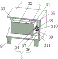
FIG. 1 is a schematic structural view of the present invention;
FIG. 2 is a right side sectional view of the present invention;
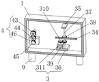
FIG. 3 is a schematic front cross-sectional view of the present invention.
In the figure: the utility model discloses a 1 box, 2 main risers, 3 tension adjusting unit, 31 fly leaf, 32 connecting plates, 33 arc cardboard, 34 racks, 35 upper supporting plate, 36 lower supporting plate, 37 rotary column, 38 cylinder gear, 39 driven gear, 310 driving gear, 311 adjustment motor, 4 play membrane units, 41 upper roll axle, 42 lower roll axle, 43 upper driven gear, 44 lower driven gear, 45 play membrane driving gear, 46 play membrane motor, 5 material loading roll axles, 6 location plectanes, 7 upper arc piece, 8 lower arc platform, 9 supporting legs.
Detailed Description
The technical solutions in the embodiments of the present invention will be clearly and completely described below with reference to the drawings in the embodiments of the present invention, and it is obvious that the described embodiments are only a part of the embodiments of the present invention, and not all of the embodiments. All other embodiments, which can be derived by a person skilled in the art from the embodiments given herein without making any creative effort, shall fall within the protection scope of the present invention.
Referring to fig. 1-3, the present embodiment provides a technical solution: a release film unreeling machine capable of adjusting tension comprises a box body 1, a tension adjusting unit 3 and a film discharging unit 4;
a box body 1: the rear end of the inside of the frame is provided with a main vertical plate 2;
tension adjusting unit 3: the vertical lifting device comprises a movable plate 31, a connecting plate 32, an arc clamping plate 33, a rack 34, a driven assembly and a power assembly, wherein the movable plate 31 is connected to the right end of a main vertical plate 2 in a sliding manner, the right end of the movable plate 31 is connected with the rear end of the connecting plate 32, the arc clamping plate 33 is installed on the left side of the front end of the connecting plate 32, the rack 34 is installed on the rear end of the movable plate 31, the driven assembly is installed at the rear end of the main vertical plate 2, and the power assembly is installed on the lower side of the rear end of the main vertical plate 2; under the action of the movable plate 31, the connecting plate 32 can drive the arc-shaped clamping plate 33 to press against the reel loaded with the release film, and the rack 34 can prepare for the movement of the movable plate 31.
Driven component contains fagging 35, lower fagging 36, rotary column 37, cylinder gear 38 and driven gear 39, fagging 35 is installed to the rear end upside of main riser 2, fagging 36 is installed down to the rear end downside of main riser 2, fagging 35 is connected in the upper end rotation of rotary column 37, fagging 36 is connected in the lower extreme rotation of rotary column 37, install cylinder gear 38 on rotary column 37's the cylinder, cylinder gear 38 is connected with the meshing of rack 34, driven gear 39 is installed on rotary column 37's cylinder and is located the downside of cylinder gear 38. The driven gear 39 rotates, the rotary column 37 drives the column gear 38 to rotate, and the column gear 38 drives the rack 34 engaged with the column gear to move, so as to adjust tension.
The power assembly comprises a driving gear 310 and an adjusting motor 311, the adjusting motor 311 is installed on the left side of the upper end of the lower supporting plate 36, an output shaft of the adjusting motor 311 is connected with the driving gear 310, and the driving gear 310 is meshed with the driven gear 39. Through the rotation of the adjusting motor 311, in the discharging process of the unreeling machine, the driving gear 310 is slowly rotated, so that the arc-shaped clamping plate 33 can continuously control the tension of the reel with the release film.
And (3) film outlet unit 4: is arranged at the left end of the main vertical plate 2.
Go out membrane unit 4 and contain roller 41, lower roller 42, go up driven gear 43, lower driven gear 44 and play membrane power component, the rear end of roller 41 is connected with the left end upside rotation of main riser 2, the rear end of roller 42 is connected with the left end downside rotation of main riser 2 down, driven gear 43 is installed to the rear end of roller 41, driven gear 44 is down installed to the rear end of roller 42 down, it is connected with lower driven gear 44 meshing to go up driven gear 43, it installs on the left side of the inside rear end of box 1 to go out membrane power component. Through the rotation of the upper roller shaft 41 and the lower roller shaft 42, the release film can be extruded between the upper roller shaft and the lower roller shaft without short time, and the unreeling is realized.
Go out membrane power module and contain out membrane driving gear 45 and go out membrane motor 46, install out membrane motor 46 on the left of the inside rear end of box 1, go out membrane motor 46's output shaft and go out membrane driving gear 45, go out membrane driving gear 45 and be connected with lower driven gear 44 meshing. When the film discharging motor 46 rotates, the film discharging driving gear 45 can rotate, so that the upper roller shaft 41 and the lower roller shaft 42 rotate to provide power for unwinding.
Still include material loading roller 5 and positioning circular plate 6, the right-hand member of main riser 2 rotates with the rear end of material loading roller 5 to be connected, and positioning circular plate 6 installs at the rear end of material loading roller 5 and does not contact with main riser 2. The winding drum with the release film can be sleeved on the feeding roller shaft 5, and the positioning circular plate 6 can avoid the contact with the main vertical plate 2, so that better discharging can be realized.
Still include arc piece 7, lower arc platform 8 and supporting leg 9, arc piece 7 is installed to the inside upper end of box 1, and arc platform 8 is installed down to the inside lower extreme of box 1, and supporting leg 9 is all installed in the bottom four corners of box 1. Go up arc piece 7 and arc platform 8 down and all can fix a position the reel that has from the type membrane that just put into, make its better unreel, supporting leg 9 provides the support for the operation of device.
The working principle of the release film unreeling machine with adjustable tension provided by the utility model is as follows: the winding drum with the release film is sleeved on the feeding roller shaft 5, the positioning circular plate 6 can avoid contact with the main vertical plate 2, one end of the release film is clamped between the upper roller shaft 41 and the lower roller shaft 42, the release film can be unreeled through rotation of the film discharging motor 46, the adjusting motor 311 slowly rotates in the unreeling process, the arc-shaped clamping plate 33 can continuously extrude the release film in the unreeling process, tension control when the release film is unreeled is achieved, and the release film can be unreeled more stably and efficiently.
It should be noted that, the adjusting motor 311 and the film discharging motor 46 disclosed in the above embodiments both adopt servo motors, the input end of the adjusting motor 311 is electrically connected to the output end of the external control switch set, the input end of the film discharging motor 46 is electrically connected to the output end of the external control switch set, the input end of the external control switch set is electrically connected to the output end of the external power supply, and the external control switch set adopts a method commonly used in the prior art to control the operation of the adjusting motor 311 and the film discharging motor 46.
The above description is only an embodiment of the present invention, and not intended to limit the scope of the present invention, and all modifications of equivalent structures and equivalent processes, which are made by using the contents of the present specification and the accompanying drawings, or directly or indirectly applied to other related technical fields, are included in the scope of the present invention.