Steel bar guiding mechanism of steel bar truss forming machine
Technical Field
The utility model relates to the technical field of steel processing, in particular to a steel bar guide mechanism of a steel bar truss forming machine.
Background
When the steel bar truss forming machine is used, the production and manufacturing standards and quality are greatly improved. Because the steel bar truss production line is manufactured in a mechanized and unified manner, the specifications and the sizes of the manufactured products are almost the same and are all produced according to the values set by the program, and errors and defective products are not easy to occur. Just because the steel bar truss production line adopts unified standard, also let the steel bar truss equipment of producing manufactured possess higher service quality, the tolerance is stronger in the use.
Therefore, the steel bar guiding mechanism of the steel bar truss forming machine is obtained by searching application No. 201110305794.9, and comprises a supporting frame, a horizontal steel bar guiding device, a connecting plate and a device for adjusting the horizontal height of the steel bar guiding device, but the steel bar guiding mechanism still has certain technical defects, so that a novel steel bar guiding mechanism of the steel bar truss forming machine is needed.
On one hand, most of the steel bar guide mechanisms of the traditional steel bar truss forming machine have poor guidance performance in actual use, so that guidance deviation is easy to occur, and the integral installation practical effect of the device is influenced;
on the other hand, the steel bar guide mechanism of the traditional steel bar truss forming machine is mostly inconvenient for workers to install and use in actual use, and the overall practical effect of the device is reduced.
SUMMERY OF THE UTILITY MODEL
The utility model aims to provide a steel bar guiding mechanism of a steel bar truss forming machine, which aims to solve the problem of poor practicability of guiding in use in the background technology.
In order to achieve the purpose, the utility model provides the following technical scheme: the utility model provides a steel bar guiding mechanism of steel bar truss make-up machine, includes connecting plate, branch, direction cardboard, ejection piece and built-in piece, horizontal extension board one and horizontal extension board two are installed to one side of branch, the ejection piece is installed at the top of branch, the connecting plate that the cooperation was used is installed at the top of ejection piece, built-in piece is installed through electric telescopic handle in the bottom in the ejection piece, the direction cardboard is installed to the bottom of built-in piece, and installs the last buckle piece that supports that cooperation direction cardboard used through the montant in the built-in piece, support the buckle piece down to install bottom in the direction cardboard, and support the bottom connection of buckle piece down and install the buffering spring part that the cooperation was used.
Preferably, a connecting rod is installed on one side of the connecting plate in a penetrating mode, and an installing connector matched with the connecting rod is installed between one end of the connecting rod and one side of the connecting plate.
Preferably, the bottom of the second transverse support plate is provided with a connecting piece through a second mounting piece, and one end of the connecting piece is connected and mounted on the built-in block through a first mounting piece.
Preferably, the bottom of the buffering spring part is provided with a base matched with the lower support buckle plate for use, and a moving block and a sliding groove matched for use are respectively arranged between one side of the lower support buckle plate and the inside of the guide buckle plate.
Preferably, the top of the guide clamping plate is provided with a first through hole used in cooperation with the upper abutting plate.
Preferably, the top of the vertical rod is connected and installed with the electric telescopic rod through the auxiliary plate, and the top of the built-in block is provided with a second through hole matched with the use.
Compared with the prior art, the utility model has the beneficial effects that:
(1) the top of the supporting rod is provided with the jacking piece, the bottom in the jacking piece is provided with the built-in block through the electric telescopic rod, the bottom of the built-in block is provided with the guide clamping plate, the built-in block is internally provided with the upper abutting buckle plate matched with the guide clamping plate for use through the vertical rod, when the device is used for guiding, a steel bar can pass through the guide clamping plate for guiding operation, and then the upper abutting buckle plate is used for clamping and fixing the steel bar in the guide clamping plate through the driving assembly on the device, so that the steel bar is stably clamped, and the integral guiding practical effect of the device is also improved;
(2) the connecting plate matched with the top mounting piece is mounted at the top of the top mounting piece, when the top mounting piece is used for guiding mounting, corresponding processing operation needs to be carried out on each guiding mechanism on a steel bar truss forming machine, the whole device can be subjected to a plurality of corresponding butt-joint mounting through the connecting assembly at the top, the operation stability of the whole device can be effectively guaranteed, processing operation of processing a plurality of steel bars is realized, and the practical effect of the whole device is improved;
(3) support the buckle plate down through the bottom installation in the cardboard that leads, and support the bottom connection of buckle plate down and install the buffering spring part that the cooperation was used, when the operation of leading uses, it supports the buckle plate down and can assist the centre gripping to the reinforcing bar when, also can alleviate the impact force that the buckle plate descends and brings effectively to the holistic practical function of device has also been improved.
Drawings
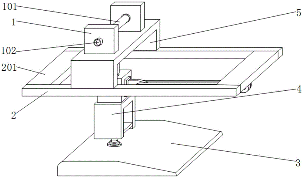
FIG. 1 is a schematic side view of the present invention;
FIG. 2 is a schematic front sectional view of the present invention;
FIG. 3 is a schematic side view of the present invention;
FIG. 4 is a schematic side view of the guide clip of the present invention;
FIG. 5 is a schematic view of the structure of the guide clip of the present invention.
In the figure: 1. a connecting plate; 101. a connecting rod; 102. installing a joint; 2. a strut; 201. a first transverse support plate; 202. a second transverse support plate; 3. a base; 4. a guide clamping plate; 401. punching a first hole; 402. a chute; 5. a top mounting piece; 501. an electric telescopic rod; 6. a built-in block; 601. punching a second hole; 7. a buffer spring member; 701. a lower propping plate; 702. a moving block; 8. a connecting member; 801. a first mounting part; 802. a second mounting part; 9. an upper resisting plate; 901. a vertical rod; 902. an auxiliary plate.
Detailed Description
The technical solutions in the embodiments of the present invention will be clearly and completely described below with reference to the drawings in the embodiments of the present invention, and it is obvious that the described embodiments are only a part of the embodiments of the present invention, and not all of the embodiments. All other embodiments, which can be derived by a person skilled in the art from the embodiments given herein without making any creative effort, shall fall within the protection scope of the present invention.
Referring to fig. 1-5, an embodiment of the present invention is shown: a steel bar guiding mechanism of a steel bar truss forming machine comprises a connecting plate 1, a supporting rod 2, a guiding clamping plate 4, a jacking piece 5 and a built-in block 6, wherein a first transverse supporting plate 201 and a second transverse supporting plate 202 are installed on one side of the supporting rod 2, a connecting piece 8 is installed at the bottom of the second transverse supporting plate 202 through a second mounting piece 802, one end of the connecting piece 8 is connected and installed on the built-in block 6 through a first mounting piece 801, the jacking piece 5 is installed at the top of the supporting rod 2, the connecting plate 1 which is used in a matched mode is installed at the top of the jacking piece 5, a connecting rod 101 penetrates through one side of the connecting plate 1, an installing joint 102 which is used in a matched mode is installed between one end of the connecting rod 101 and one side of the connecting plate 1, and the built-in block 6 is installed at the bottom in the jacking piece 5 through an electric telescopic rod 501;
specifically, the connecting plate 1 which is used in a matched mode is installed at the top of the top installation piece 5, when the top installation piece is used in a guiding mode, corresponding processing operation needs to be carried out on a guide mechanism on a steel bar truss forming machine, the whole device can be installed in a plurality of corresponding butt joints through the connecting assembly at the top, the operation stability of the whole device can be effectively guaranteed, processing operation of processing a plurality of steel bars is achieved, and the practical effect of the whole device is improved;
specifically, a guide clamping plate 4 is installed at the bottom of the built-in block 6, an upper abutting buckle plate 9 matched with the guide clamping plate 4 for use is installed in the built-in block 6 through a vertical rod 901, a first through hole 401 matched with the upper abutting buckle plate 9 for use is formed in the top of the guide clamping plate 4, the top of the vertical rod 901 is connected with an electric telescopic rod 501 through an auxiliary plate 902, and a second through hole 601 matched with the built-in block 6 is formed in the top of the built-in block 6;
specifically, the top of the supporting rod 2 is provided with the jacking piece 5, the bottom of the jacking piece 5 is provided with the built-in block 6 through the electric telescopic rod 501, the bottom of the built-in block 6 is provided with the guide clamping plate 4, the built-in block 6 is internally provided with the upper abutting buckle plate 9 matched with the guide clamping plate 4 for use through the vertical rod 901, when the device is used for guiding, a steel bar can pass through the guide clamping plate 4 for guiding operation, and then the upper abutting buckle plate 9 clamps and fixes the steel bar in the guide clamping plate 4 through the driving component on the device, so that the steel bar is stably clamped, and the integral guiding practical effect of the device is also improved;
specifically, a lower abutting plate 701 is installed at the bottom inside the guide clamping plate 4, a buffer spring part 7 matched with the lower abutting plate 701 is connected and installed at the bottom of the lower abutting plate 701, a base 3 matched with the lower abutting plate 701 is installed at the bottom of the buffer spring part 7, and a moving block 702 and a sliding groove 402 matched with the lower abutting plate 701 are respectively arranged between one side of the lower abutting plate 701 and the inside of the guide clamping plate 4;
specifically, the lower retaining plate 701 is installed at the bottom in the guide clamping plate 4, the bottom of the lower retaining plate 701 is connected with the buffer spring part 7 which is used in a matched mode, and when the guide clamping plate is used in guiding operation, the lower retaining plate 701 can assist the steel bars in clamping and can effectively relieve the impact force caused by the descending of the upper retaining plate 9.
The working principle is as follows: when the device is used, firstly, the top of the supporting rod 2 is provided with the jacking piece 5, the bottom of the jacking piece 5 is provided with the built-in block 6 through the electric telescopic rod 501, the bottom of the built-in block 6 is provided with the guide clamping plate 4, the built-in block 6 is internally provided with the upper abutting buckle plate 9 matched with the guide clamping plate 4 for use through the vertical rod 901, when the device is used for guiding, a steel bar of the device can pass through the guide clamping plate 4 for guiding operation, and then the upper abutting buckle plate 9 clamps and fixes the steel bar in the guide clamping plate 4 through the driving component on the device;
then, the connecting plate 1 which is matched with the top mounting piece 5 is mounted at the top of the top mounting piece, when the top mounting piece is used for guiding and mounting, corresponding processing operation needs to be carried out on each guiding mechanism on the steel bar truss forming machine, the whole device can be subjected to a plurality of corresponding butt joint installation through the connecting assembly at the top, and then processing operation of processing a plurality of steel bars is realized;
finally, a lower abutting plate 701 is installed at the bottom in the guide clamping plate 4, and the bottom of the lower abutting plate 701 is connected with a buffer spring part 7 which is used in a matched mode, so that when the guide clamping plate is used in guiding operation, the lower abutting plate 701 can assist in clamping the reinforcing steel bars, and meanwhile impact force caused by descending of the upper abutting plate 9 can be effectively relieved.
It will be evident to those skilled in the art that the utility model is not limited to the details of the foregoing illustrative embodiments, and that the present invention may be embodied in other specific forms without departing from the spirit or essential attributes thereof. The present embodiments are therefore to be considered in all respects as illustrative and not restrictive, the scope of the utility model being indicated by the appended claims rather than by the foregoing description, and all changes which come within the meaning and range of equivalency of the claims are therefore intended to be embraced therein. Any reference sign in a claim should not be construed as limiting the claim concerned.