CN216061577U - Ventilation device for realizing different ventilation states of two lungs - Google Patents
Ventilation device for realizing different ventilation states of two lungs Download PDFInfo
- Publication number
- CN216061577U CN216061577U CN202121102289.XU CN202121102289U CN216061577U CN 216061577 U CN216061577 U CN 216061577U CN 202121102289 U CN202121102289 U CN 202121102289U CN 216061577 U CN216061577 U CN 216061577U
- Authority
- CN
- China
- Prior art keywords
- ventilation
- conduit
- pipe
- catheter
- lungs
- Prior art date
- Legal status (The legal status is an assumption and is not a legal conclusion. Google has not performed a legal analysis and makes no representation as to the accuracy of the status listed.)
- Expired - Fee Related
Links
- 238000009423 ventilation Methods 0.000 title claims abstract description 58
- 210000004072 lung Anatomy 0.000 title claims abstract description 36
- 230000002980 postoperative effect Effects 0.000 abstract description 5
- 230000002685 pulmonary effect Effects 0.000 abstract description 4
- 230000000241 respiratory effect Effects 0.000 abstract description 2
- 210000000621 bronchi Anatomy 0.000 description 5
- 238000010586 diagram Methods 0.000 description 3
- 230000029058 respiratory gaseous exchange Effects 0.000 description 3
- 238000000034 method Methods 0.000 description 2
- 210000003456 pulmonary alveoli Anatomy 0.000 description 2
- 238000005276 aerator Methods 0.000 description 1
- 230000009977 dual effect Effects 0.000 description 1
- 238000012986 modification Methods 0.000 description 1
- 230000004048 modification Effects 0.000 description 1
- 230000033764 rhythmic process Effects 0.000 description 1
- 238000001356 surgical procedure Methods 0.000 description 1
- 210000000115 thoracic cavity Anatomy 0.000 description 1
- 210000003437 trachea Anatomy 0.000 description 1
- 238000013022 venting Methods 0.000 description 1
Images


Landscapes
- External Artificial Organs (AREA)
Abstract
The utility model provides a ventilation device for realizing different ventilation states of two lungs, which belongs to the technical field of medical instruments and comprises a main pipe, a double-cavity bronchial catheter, an air bag and an air bag inflation pipe, wherein the air bag is arranged on the outer side of the double-cavity bronchial catheter, the air bag is connected with the air bag inflation pipe, the air bag inflation pipe is used for realizing inflation or exhaust of the air bag, the ventilation device further comprises a three-cavity ventilation pipe and a connector, one end of the three-cavity ventilation pipe is connected with the main pipe, the other end of the three-cavity ventilation pipe is connected with the double-cavity bronchial catheter through the connector, the three-cavity ventilation pipe comprises a second catheter, and a timing valve is arranged on the second catheter. The ventilation device can control ventilation of the two lungs according to different tidal volumes, frequencies and pressures, effectively ensures that the operative lung operation can keep a smaller respiratory state relative to the non-operative lung operation, and the operative lung operation is fully expanded after the operation so as to reduce postoperative pulmonary complications.
Description
Technical Field
The utility model belongs to the technical field of medical instruments, and particularly relates to a ventilation device for realizing different ventilation states of two lungs.
Background
At present, in thoracic surgery, a unilung ventilation technique is generally adopted, that is, a lung on a non-operation side is ventilated, and a lung on an operation side is not ventilated, so that the lung on the operation side is in a collapse state.
SUMMERY OF THE UTILITY MODEL
In view of the above, the present invention is directed to a ventilation device capable of reducing postoperative pulmonary complications and achieving different ventilation states of both lungs.
In order to achieve the purpose, the technical scheme of the utility model is realized as follows: realize different ventilation state's of both sides lung ventilation device, including being responsible for, two-chamber endotracheal tube, gasbag and gasbag gas tube, the outside of two-chamber endotracheal tube is provided with the gasbag, the gasbag is connected with the gasbag gas tube, the gasbag gas tube is used for realizing the aerifing or the exhaust of gasbag, ventilation device still includes three chamber breather pipes and connects, three chamber breather pipe one end with be responsible for and connect, the other end passes through connect with two-chamber endotracheal tube connects, three chamber breather pipes include the second pipe, be provided with timing valve on the second pipe.
Further, three chamber breather pipes include full air-permeable pipe, first pipe, second pipe, pressure limiting valve, relief pressure valve and exhale the pipe, the one end of full air-permeable pipe, first pipe and second pipe is merged into a pipe, simultaneously, the other end of full air-permeable pipe with the articulate, the other end of first pipe and second pipe is merged into a pipe then with the articulate, the pressure limiting valve sets up on the first pipe, the relief pressure valve sets up on the second pipe, exhale the pipe setting and be in the second pipe is close to one side of joint, just exhale the pipe with the lumen of second pipe communicates with each other, be provided with the check valve that has timing function on the exhale pipe.
Furthermore, pressure gauges are respectively arranged on the pressure reducing valve and the pressure limiting valve.
Further, a timing valve arranged on the second conduit is arranged between the pressure reducing valve and the main pipe.
Furthermore, the joint comprises a connecting block and two connecting through holes, wherein the two connecting through holes are arranged in the connecting block, one end of each connecting through hole is used for connecting the full-ventilation catheter, the other end of each connecting through hole is used for connecting the double-cavity bronchial catheter, the other end of each connecting through hole is used for connecting the merging end of the first catheter and the merging end of the second catheter, and the other end of each connecting through hole is used for connecting the double-cavity bronchial catheter.
Furthermore, a bronchus cuff is arranged on the outer side of the tail end of the double-cavity bronchus catheter, the bronchus cuff is connected with a cuff inflation tube, and the cuff inflation tube is used for inflating or exhausting the bronchus cuff.
Compared with the prior art, the ventilation device for realizing different ventilation states of the two lungs has the following advantages: the ventilation device disclosed by the utility model controls ventilation of the two lungs with different tidal volumes, frequencies and pressures, so that the respiratory state of the lung on the operative side can be kept relatively smaller than that of the lung on the non-operative side in the lung operation, and the lung is fully expanded after the operation, so that postoperative pulmonary complications are reduced.
Drawings
The accompanying drawings, which are incorporated in and constitute a part of this specification, illustrate an embodiment of the utility model and, together with the description, serve to explain the utility model and not to limit the utility model. In the drawings:
FIG. 1 is a schematic structural diagram of an embodiment of an aerator apparatus according to the present invention;
FIG. 2 is a schematic structural diagram of a three-chamber vent pipe according to an embodiment of the present invention;
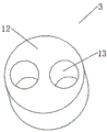
fig. 3 is a schematic structural diagram of a joint according to an embodiment of the present invention.
Description of reference numerals:
1. a main pipe; 2. a three-cavity vent pipe; 3. a joint; 4. a dual lumen bronchial catheter; 5. an air bag; 6. an air bag inflation tube; 7. a full-venting conduit; 8. a first conduit; 9. a second conduit; 10. a pressure limiting valve; 11. a pressure reducing valve; 12. connecting blocks; 13. a connecting through hole; 14. a bronchial cuff; 15. A cuff inflation tube; 16. an expiratory conduit.
Detailed Description
It should be noted that the embodiments and features of the embodiments may be combined with each other without conflict.
In the description of the present invention, it is to be understood that the terms "center", "longitudinal", "lateral", "up", "down", "front", "back", "left", "right", "vertical", "horizontal", "top", "bottom", "inner", "outer", and the like, indicate orientations or positional relationships based on those shown in the drawings, and are used only for convenience in describing the present invention and for simplicity in description, and do not indicate or imply that the referenced devices or elements must have a particular orientation, be constructed and operated in a particular orientation, and thus, are not to be construed as limiting the present invention. Furthermore, the terms "first", "second", etc. are used for descriptive purposes only and are not to be construed as indicating or implying relative importance or implicitly indicating the number of technical features indicated. Thus, a feature defined as "first," "second," etc. may explicitly or implicitly include one or more of that feature. In the description of the present invention, "a plurality" means two or more unless otherwise specified.
In the description of the present invention, it should be noted that, unless otherwise explicitly specified or limited, the terms "mounted," "connected," and "connected" are to be construed broadly, e.g., as meaning either a fixed connection, a removable connection, or an integral connection; can be mechanically or electrically connected; they may be connected directly or indirectly through intervening media, or they may be interconnected between two elements. The specific meaning of the above terms in the present invention can be understood by those of ordinary skill in the art through specific situations.
The present invention will be described in detail below with reference to the embodiments with reference to the attached drawings.
As shown in fig. 1-3, the ventilation device of the present invention for realizing different ventilation states of two lungs comprises a main tube 1, a dual-cavity bronchial tube 4, an air bag 5 and an air bag inflation tube 6, wherein the air bag 5 is arranged outside the dual-cavity bronchial tube 4, the air bag 5 is connected to the air bag inflation tube 6, the air bag inflation tube 6 is used for realizing inflation or exhaust of the air bag 5, the ventilation device further comprises a three-cavity ventilation tube 2 and a connector 3, one end of the three-cavity ventilation tube 2 is connected to the main tube 1, the other end of the three-cavity ventilation tube is connected to the dual-cavity bronchial tube 4 through the connector 3, one end of the main tube 1 far away from the three-cavity ventilation tube 2 is connected to a ventilator, and the ventilator is in the prior art.
The three-cavity vent pipe 2 comprises a full-vent pipe 7, a first pipe 8, a second pipe 9, a pressure limiting valve 10, a pressure reducing valve 11 and an expiration pipe 16, one end of the full-vent pipe 7, one end of the first pipe 8 and one end of the second pipe 9 are combined into one pipe, meanwhile, the other end of the full-vent pipe 7 is connected with the joint 3, the other end of the first pipe 8 and the other end of the second pipe 9 are combined into one pipe and then connected with the joint 3, the pressure reducing valve 11 is arranged on the second pipe 9, the pressure of the gas fed by the respirator can be reduced through the pressure reducing valve 11, the pressure of the second pipe 9 on the operation side is kept constant, the pressure can be adjusted according to actual conditions, and the gas higher than a pressure set value cannot enter the lungs on the operation side, for example: the pressure reducing valve 11 can be adjusted to only pass 10cmH2Gas of O pressure, ventilator given 30cmH2O gas, the lung at the operation side is only 10cmH2The gas with O pressure is used for ventilation with small tidal volume, thereby facilitating the operation of a doctor, and the lung on the other side is normal 30cmH2The gas of O is mechanically aerated. The pressure limiting valve 10 is arranged atOn the first conduit 8, after the operation is finished, the operation side lung needs to keep a certain expansion degree of the alveolus at the end of expiration, the pressure limiting valve 10 can maintain the pressure in the operation side lung at a certain value, and the gas smaller than the pressure value is not discharged, so that the alveolus at the operation side keeps an open state with at least certain pressure, such as: after the operation is finished, the pressure limiting valve 10 is adjusted to maintain 10cmH2Gas under O pressure, the operative lung always has 10H2O pressure gas, which keeps the alveoli collapsed due to small tidal volume in the operation fully expanded after the operation and reduces the occurrence of postoperative pulmonary complications, wherein the expiratory conduit 16 is arranged at one side of the second conduit 9 close to the joint 3, the expiratory conduit 16 is communicated with the lumen of the second conduit 9, and a one-way valve with a timing function is arranged on the expiratory conduit 16 and is used for ensuring that the expiratory conduit 16 can normally exhaust outwards during the expiration.
Pressure gauges are respectively arranged on the pressure reducing valve 11 and the pressure limiting valve 10, so that an operator can conveniently and visually read the set pressure value of the pressure reducing valve 11 or the pressure limiting valve 10.
Be provided with the timing valve on the second pipe 9, simultaneously the timing valve that sets up on the second pipe 9 is installed relief pressure valve 11 with be responsible for between 1, the timing valve can control the second pipe 9 ventilate or close the gas time, and the operator adjusts the timing valve according to actual need to realize the different frequency of ventilating of operation side lung and non-operation side lung, the timing valve is linked with the breathing machine, thereby realizes better breathing rhythm unified control.
The joint 3 comprises a connecting block 12 and two connecting through holes 13, wherein the connecting through holes 13 are arranged in the connecting block 12, one end of one of the connecting through holes 13 is used for connecting the full-ventilation catheter 7, the other end of the connecting through hole is used for connecting the double-cavity bronchial catheter 4, the other end of the other connecting through hole 13 is used for connecting the merging end of the first catheter 8 and the second catheter 9, and the other end of the connecting through hole 13 is used for connecting the double-cavity bronchial catheter 4.
The outer side of the tail end of the double-cavity bronchial catheter 4 is provided with a bronchial cuff 14, the bronchial cuff 14 is connected with a cuff inflating tube 15, and the cuff inflating tube 15 is used for inflating or exhausting the bronchial cuff 14.
The presence of the balloon 5 and the bronchial cuff 14 serves to secure the ventilation device in position and prevent air leakage during lung ventilation.
In the actual work process, at first place into patient's trachea with two-chamber endotracheal tube 4 through patient's mouth, and inflate through gasbag 5 and bronchus cuff 14 and fix it in corresponding position, be connected person in charge 1 with the breathing machine, close pressure limiting valve 10, open relief pressure valve 11 and set for the pressure value that the operation needs, open timing valve simultaneously and set for the frequency of ventilating, can carry out the operation, after the operation, close relief pressure valve 11 and timing valve, set for pressure limiting valve 10 pressure and open pressure limiting valve 10 can, so that let the less lung postoperative of ventilating in the operation fully expand.
The above description is only for the purpose of illustrating the preferred embodiments of the present invention and is not to be construed as limiting the utility model, and any modifications, equivalents, improvements and the like that fall within the spirit and principle of the present invention are intended to be included therein.
Claims (6)
Priority Applications (1)
| Application Number | Priority Date | Filing Date | Title |
|---|---|---|---|
| CN202121102289.XU CN216061577U (en) | 2021-05-21 | 2021-05-21 | Ventilation device for realizing different ventilation states of two lungs |
Applications Claiming Priority (1)
| Application Number | Priority Date | Filing Date | Title |
|---|---|---|---|
| CN202121102289.XU CN216061577U (en) | 2021-05-21 | 2021-05-21 | Ventilation device for realizing different ventilation states of two lungs |
Publications (1)
| Publication Number | Publication Date |
|---|---|
| CN216061577U true CN216061577U (en) | 2022-03-18 |
Family
ID=80662507
Family Applications (1)
| Application Number | Title | Priority Date | Filing Date |
|---|---|---|---|
| CN202121102289.XU Expired - Fee Related CN216061577U (en) | 2021-05-21 | 2021-05-21 | Ventilation device for realizing different ventilation states of two lungs |
Country Status (1)
| Country | Link |
|---|---|
| CN (1) | CN216061577U (en) |
-
2021
- 2021-05-21 CN CN202121102289.XU patent/CN216061577U/en not_active Expired - Fee Related
Similar Documents
| Publication | Publication Date | Title |
|---|---|---|
| US20130047993A1 (en) | Tracheal tube having a flange with a variable volume | |
| CN110237390A (en) | artificial airway | |
| CN110585544A (en) | Endotracheal tube with adjustable internal diameter | |
| CN102068742A (en) | Single-cavity multi-bag trachea catheter | |
| CN201558393U (en) | Single-cavity multi-bag tracheal tube | |
| CN218075112U (en) | Disposable multi-bag right lung bronchus blocking device | |
| CN213823033U (en) | Ventilation device for realizing different ventilation states of two lungs | |
| CN215537526U (en) | Tube wall-free right double-cavity bronchial catheter | |
| CN209713913U (en) | Right double lumen endobronchial tube | |
| CN219354982U (en) | Laryngeal mask with adapter | |
| CN220309390U (en) | Synchronous chest wall supercharging system breathes in | |
| CN110448775A (en) | Airway is isolated in lung | |
| CN210078522U (en) | Formula of can letting out trachea shutoff type trachea cannula | |
| CN217311503U (en) | A high-frequency jet ventilation tracheal tube | |
| CN213789429U (en) | Single-lumen double-balloon endotracheal tube | |
| CN113425965B (en) | Bronchial catheter and catheter assembly for accurate pulmonary re-tensioning | |
| CN213131409U (en) | Inflatable tracheal catheter | |
| CN214970705U (en) | Bronchus two-chamber intubate | |
| CN207085036U (en) | Exempt to inflate drainage laryngeal mask tracheal catheter | |
| CN211024645U (en) | Lung isolation ventilation catheter | |
| CN113384791A (en) | Tube wall-free right double-cavity bronchial catheter | |
| CN112336957A (en) | Double-cavity bronchial catheter for realizing rapid collapse of lateral lung of operation | |
| CN209451092U (en) | A kind of air bag expansion formula tracheal catheter | |
| CN213048830U (en) | Double-cavity bronchial cannula capable of avoiding cross infection of patients | |
| CN223112115U (en) | A tracheal tube |
Legal Events
| Date | Code | Title | Description |
|---|---|---|---|
| GR01 | Patent grant | ||
| GR01 | Patent grant | ||
| CF01 | Termination of patent right due to non-payment of annual fee | ||
| CF01 | Termination of patent right due to non-payment of annual fee |
Granted publication date: 20220318 |