CN216059418U - Portable anti-skid sole - Google Patents
Portable anti-skid sole Download PDFInfo
- Publication number
- CN216059418U CN216059418U CN202122332598.2U CN202122332598U CN216059418U CN 216059418 U CN216059418 U CN 216059418U CN 202122332598 U CN202122332598 U CN 202122332598U CN 216059418 U CN216059418 U CN 216059418U
- Authority
- CN
- China
- Prior art keywords
- sole
- skidding
- skid
- groove
- rotating
- Prior art date
- Legal status (The legal status is an assumption and is not a legal conclusion. Google has not performed a legal analysis and makes no representation as to the accuracy of the status listed.)
- Expired - Fee Related
Links
- 230000035939 shock Effects 0.000 claims description 20
- 238000010521 absorption reaction Methods 0.000 claims 5
- 238000013016 damping Methods 0.000 abstract description 7
- 230000000694 effects Effects 0.000 abstract description 5
- 230000009286 beneficial effect Effects 0.000 description 1
- 239000000155 melt Substances 0.000 description 1
- 238000000926 separation method Methods 0.000 description 1
- XLYOFNOQVPJJNP-UHFFFAOYSA-N water Substances O XLYOFNOQVPJJNP-UHFFFAOYSA-N 0.000 description 1
Images




Landscapes
- Footwear And Its Accessory, Manufacturing Method And Apparatuses (AREA)
Abstract
The utility model relates to the technical field of articles for daily use, and discloses a portable anti-skidding sole, which comprises a sole, wherein a damping mechanism is arranged on the upper side of the sole, an anti-skidding mechanism is arranged on the lower side of the sole, a fixed short column is arranged on one side of the anti-skidding mechanism, the anti-skidding mechanism comprises a rotating connecting rod, an anti-skidding plate is connected to one side of the rotating connecting rod, a plurality of anti-skidding nails are arranged on the outer side of the anti-skidding plate, and a rotating limiting groove and a fixed limiting groove are formed in the middle of the rotating connecting rod. The anti-skid device is fixed in different nut grooves through the positioning screw rods, so that the anti-skid purpose of toe parts or heel parts is achieved, the positioning screw rods rotate in the fixed limiting grooves, when an anti-skid mechanism is not needed, the positioning screw rods and the separable rotating rods are taken down, a user can use the anti-skid device conveniently, the anti-skid nails on the anti-skid plates have a better anti-skid effect, the fixing edges are convenient to install the damping mechanism, and the anti-skid heels meet the common anti-skid requirement when the anti-skid mechanism is not available.
Description
Technical Field
The utility model relates to the technical field of articles for daily use, in particular to a portable anti-skidding sole.
Background
After snow or accumulated water on the road surface freezes into ice after snowing in winter, the road surface becomes very wet and slippery and is easy to slip, and pedestrians are not convenient to walk. People often wear different shoes to deal with different ground conditions.
Most current anti-skidding shoes only increase the degree of depth of decorative pattern at the sole, and this kind of way is good to the possible effect of snow, but to the ice sheet that forms after ponding melts, the anti-skidding measure of decorative pattern formula is often not good enough, can not be fine realization anti-skidding effect. Accordingly, those skilled in the art have provided a portable anti-slip shoe sole to solve the problems set forth in the above background art.
Disclosure of Invention
The present invention is directed to a portable anti-slip sole for solving the above-mentioned problems of the prior art.
In order to achieve the purpose, the utility model provides the following technical scheme:
portable anti-skidding sole, including the sole, the upside of sole is provided with damper, the downside of sole is provided with anti-skidding mechanism, one side of anti-skidding mechanism is provided with fixed short column, anti-skidding mechanism is including rotating the connecting rod, one side of rotating the connecting rod is connected with the antiskid ribbed tile, the outside of antiskid ribbed tile is provided with a plurality of antiskid ribbed tile, the centre of rotating the connecting rod has been seted up and has been rotated spacing groove and fixed spacing groove, the centre of rotating the spacing groove is provided with separable dwang, the centre of fixed spacing groove is provided with positioning screw, the sole includes the sole body, the upside intermediate position of sole body is provided with the constant head tank, the nut groove has been seted up to the both sides of constant head tank.
As a still further scheme of the utility model: the edge of the upper end of one side of the sole body is provided with a fixed edge, and the two ends of the upper side of the sole body are provided with limit holes.
As a still further scheme of the utility model: the downside of sole body is provided with a set of fixed slot, the lower extreme edge of sole body one side is provided with anti-skidding heel.
As a still further scheme of the utility model: separable dwang and constant head tank phase-match, positioning screw and nut groove phase-match.
As a still further scheme of the utility model: the rotary connecting rod is fixedly connected with the antiskid plate, and the antiskid plate is fixedly connected with the antiskid nails.
As a still further scheme of the utility model: the anti-skid mechanism is fixedly connected with the fixed short columns, the fixed grooves are matched with the fixed short columns, and the sole body is fixedly connected with the anti-skid heels.
As a still further scheme of the utility model: damping mechanism includes the shock attenuation shoe-pad, the both ends of shock attenuation shoe-pad downside are provided with spacing circular gasket, first auxiliary tank has been seted up to the intermediate position of shock attenuation shoe-pad downside, the second auxiliary tank has all been seted up to the both sides that the downside of shock attenuation shoe-pad is located first auxiliary tank.
As a still further scheme of the utility model: spacing round gasket and spacing hole phase-match, first supplementary groove and separable dwang phase-match, the supplementary groove of second and positioning screw phase-match.
Compared with the prior art, the utility model has the beneficial effects that:
1. make its separation through rotating positioning screw, later make the rotation connecting rod rotate round rotating separable dwang, make fixed stub inlay in different fixed slots, separable dwang inlay in rotating the limiting groove internal rotation, fix positioning screw at different nut inslots again, thereby reach the anti-skidding purpose at toe position or heel position, positioning screw is at fixed limiting groove internal rotation, through taking off positioning screw and separable dwang when not needing anti-skidding mechanism, the person of facilitating the use uses, the antiskid nail on the antiskid ribbed tile plays better anti-skidding effect, fixed limit easy to assemble damper, the ordinary anti-skidding demand when anti-skidding heel plays no anti-skidding mechanism.
2. Inlay in spacing downthehole through the spacing circle gasket card with on the shock attenuation shoe-pad, make the shock attenuation shoe-pad can not remove easily, make separable dwang and positioning screw can not oppress the shock attenuation shoe-pad through first auxiliary groove and second auxiliary groove, make things convenient for the staff to separate separable dwang and positioning screw simultaneously.
Drawings
FIG. 1 is a schematic structural view of a portable anti-slip sole;
FIG. 2 is an exploded view of the portable anti-slip sole;
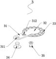
FIG. 3 is a schematic structural view of an anti-slip mechanism in the portable anti-slip shoe sole;
FIG. 4 is a schematic structural view of a sole of the portable anti-slip shoe sole;
fig. 5 is a schematic structural view of a shock-absorbing mechanism in a portable anti-slip shoe sole.
In the figure: 1. a sole; 11. a sole body; 12. fixing the edge; 13. a limiting hole; 14. positioning a groove; 15. a nut groove; 16. anti-skid heels; 17. fixing grooves; 2. a damping mechanism; 21. shock-absorbing insoles; 22. a limiting round gasket; 23. a first auxiliary groove; 24. a second auxiliary groove; 3. an anti-slip mechanism; 30. a fixed short column; 31. rotating the connecting rod; 311. rotating the limiting groove; 312. fixing a limit groove; 32. an anti-skid plate; 33. anti-skid nails; 34. the rotating rod can be separated; 35. and (5) positioning the screw rod.
Detailed Description
Referring to fig. 1 to 5, in the embodiment of the present invention, the portable anti-slip shoe sole includes a shoe sole 1, a shock absorbing mechanism 2 is disposed on an upper side of the shoe sole 1, an anti-slip mechanism 3 is disposed on a lower side of the shoe sole 1, a fixing short column 30 is disposed on one side of the anti-slip mechanism 3, the anti-slip mechanism 3 includes a rotating connecting rod 31, an anti-slip plate 32 is connected to one side of the rotating connecting rod 31, a plurality of anti-slip nails 33 are disposed on an outer side of the anti-slip plate 32, a rotating limiting groove 311 and a fixing limiting groove 312 are disposed in a middle of the rotating connecting rod 31, a separable rotating rod 34 is disposed in a middle of the rotating limiting groove 311, a positioning screw 35 is disposed in a middle of the fixing limiting groove 312, the shoe sole 1 includes a shoe sole body 11, a positioning groove 14 is disposed in a middle position on an upper side of the shoe sole body 11, and nut grooves 15 are disposed on two sides of the positioning groove 14.
In fig. 1, 2, 3 and 4: the edge of the upper end of one side of the sole body 11 is provided with a fixed edge 12, both ends of the upper side of the sole body 11 are provided with limit holes 13, the lower side of the sole body 11 is provided with a group of fixed grooves 17, the edge of the lower end of one side of the sole body 11 is provided with an antiskid heel 16, a separable rotating rod 34 is matched with a locating groove 14, a locating screw 35 is matched with a nut groove 15, a rotating connecting rod 31 is fixedly connected with an antiskid plate 32, the antiskid plate 32 is fixedly connected with an antiskid nail 33, an antiskid mechanism 3 is fixedly connected with a fixed short column 30, the fixed groove 17 is matched with a fixed short column 30, the sole body 11 is fixedly connected with the antiskid heel 16, the rotating connecting rod 35 is separated by rotating, then the rotating connecting rod 31 rotates around the separable rotating rod 34, the fixed short column 30 is clamped in different fixed grooves 17, the separable rotating rod 34 is clamped in the rotating limit groove 311, fix the positioning screw 35 in different nut grooves 15 again to reach the antiskid purpose at toe position or heel position, positioning screw 35 is at fixed spacing inslot 312 internal rotation, through taking off positioning screw 35 and separable dwang 34 when needing no anti-skidding mechanism 3, the person of facilitating the use uses, the antiskid nail 33 on the antiskid ribbed tile 32 plays better anti-skidding effect, fixed limit 12 is easy to assemble damper 2, ordinary antiskid demand when anti-skidding heel 16 plays no anti-skidding mechanism 3.
In fig. 1, 2 and 5: damper 2 includes shock attenuation shoe-pad 21, the both ends of shock attenuation shoe-pad 21 downside are provided with spacing round gasket 22, first auxiliary groove 23 has been seted up to the intermediate position of shock attenuation shoe-pad 21 downside, second auxiliary groove 24 has all been seted up to the both sides that the downside of shock attenuation shoe-pad 21 is located first auxiliary groove 23, spacing round gasket 22 and spacing hole 13 phase-match, first auxiliary groove 23 and separable dwang 34 phase-match, second auxiliary groove 24 and positioning screw 35 phase-match, through spacing round gasket 22 inlay card on shock attenuation shoe-pad 21 in spacing hole 13, make shock attenuation shoe-pad 21 can not remove easily, make separable dwang 34 and positioning screw 35 can not oppress shock attenuation shoe-pad 21 through first auxiliary groove 23 and second auxiliary groove 24, make things convenient for the staff to separate separable dwang 34 and positioning screw 35 simultaneously.
The working principle of the utility model is as follows: the positioning screw rods 35 are separated by rotating, then the rotating connecting rod 31 rotates around the rotating separable rotating rod 34, the fixed short columns 30 are clamped and embedded in different fixed grooves 17, the separable rotating rod 34 is clamped and embedded in the rotating limiting groove 311 to rotate, the positioning screw rods 35 are fixed in different nut grooves 15, so that the anti-skidding purpose of toe parts or heel parts is achieved, the positioning screw rods 35 rotate in the fixed limiting grooves 312, when the anti-skidding mechanism 3 is not needed, the use of a user is facilitated by taking down the positioning screw rods 35 and the separable rotating rod 34, the anti-skidding nails 33 on the anti-skidding plates 32 play a better anti-skidding role, the fixed edges 12 are convenient to install the damping mechanism 2, the anti-skidding heels 16 play a common anti-skidding requirement when the anti-skidding mechanism 3 is not available, and the damping insoles 21 cannot easily move by clamping and embedding the limiting round gaskets 22 on the damping insoles 21 in the limiting holes 13, the separable rotating rod 34 and the positioning screw 35 do not press the shock-absorbing insole 21 through the first auxiliary groove 23 and the second auxiliary groove 24, and at the same time, the worker can separate the separable rotating rod 34 and the positioning screw 35 conveniently.
The above description is only for the preferred embodiment of the present invention, but the scope of the present invention is not limited thereto, and any person skilled in the art should be considered to be within the scope of the present invention, and the technical solutions and the utility model concepts of the present invention are equivalent to or changed within the scope of the present invention.
Claims (8)
1. Portable anti-skidding sole, including sole (1), its characterized in that, the upside of sole (1) is provided with damper (2), the downside of sole (1) is provided with anti-skidding mechanism (3), one side of anti-skidding mechanism (3) is provided with fixed short column (30), anti-skidding mechanism (3) includes rotates connecting rod (31), one side of rotating connecting rod (31) is connected with antiskid ribbed tile (32), the outside of antiskid ribbed tile (32) is provided with a plurality of antiskid ribbed tile (33), rotation spacing groove (311) and fixed spacing groove (312) have been seted up to the centre of rotating connecting rod (31), the centre of rotating spacing groove (311) is provided with separable dwang (34), the centre of fixed spacing groove (312) is provided with positioning screw (35), sole (1) includes sole body (11), the upside intermediate position of sole body (11) is provided with constant head tank (14), and nut grooves (15) are formed in two sides of the positioning groove (14).
2. The portable anti-skidding sole according to claim 1, wherein a fixing edge (12) is arranged at the edge of the upper end of one side of the sole body (11), and limiting holes (13) are formed at two ends of the upper side of the sole body (11).
3. The portable non-slip shoe sole according to claim 1, wherein a set of fixing grooves (17) is provided at a lower side of the sole body (11), and a non-slip heel (16) is provided at a lower end edge of one side of the sole body (11).
4. The portable anti-slip shoe sole according to claim 1, characterized in that the separable rotating rod (34) matches with the positioning groove (14), and the positioning screw (35) matches with the nut groove (15).
5. The portable anti-slip shoe sole according to claim 1, characterized in that said rotation link (31) is fixedly connected to a cleat (32), said cleat (32) being fixedly connected to a cleat (33).
6. The portable anti-slip shoe sole according to claim 3, characterized in that the anti-slip mechanism (3) is fixedly connected with the fixing studs (30), the fixing grooves (17) are matched with the fixing studs (30), and the shoe sole body (11) is fixedly connected with the anti-slip shoe heel (16).
7. The portable anti-slip shoe sole according to claim 1, wherein the shock absorption mechanism (2) comprises a shock absorption insole (21), both ends of the lower side of the shock absorption insole (21) are provided with limiting round gaskets (22), a first auxiliary groove (23) is formed in the middle of the lower side of the shock absorption insole (21), and both sides of the lower side of the shock absorption insole (21) positioned in the first auxiliary groove (23) are provided with second auxiliary grooves (24).
8. The portable anti-slip shoe sole according to claim 7, wherein the limiting round gasket (22) is matched with the limiting hole (13), the first auxiliary groove (23) is matched with the separable rotating rod (34), and the second auxiliary groove (24) is matched with the positioning screw (35).
Priority Applications (1)
| Application Number | Priority Date | Filing Date | Title |
|---|---|---|---|
| CN202122332598.2U CN216059418U (en) | 2021-09-26 | 2021-09-26 | Portable anti-skid sole |
Applications Claiming Priority (1)
| Application Number | Priority Date | Filing Date | Title |
|---|---|---|---|
| CN202122332598.2U CN216059418U (en) | 2021-09-26 | 2021-09-26 | Portable anti-skid sole |
Publications (1)
| Publication Number | Publication Date |
|---|---|
| CN216059418U true CN216059418U (en) | 2022-03-18 |
Family
ID=80635750
Family Applications (1)
| Application Number | Title | Priority Date | Filing Date |
|---|---|---|---|
| CN202122332598.2U Expired - Fee Related CN216059418U (en) | 2021-09-26 | 2021-09-26 | Portable anti-skid sole |
Country Status (1)
| Country | Link |
|---|---|
| CN (1) | CN216059418U (en) |
Cited By (1)
| Publication number | Priority date | Publication date | Assignee | Title |
|---|---|---|---|---|
| CN117137225A (en) * | 2023-09-21 | 2023-12-01 | 福建鸿星尔克体育用品有限公司 | Cushioning and sprain-proof sole and shoe |
-
2021
- 2021-09-26 CN CN202122332598.2U patent/CN216059418U/en not_active Expired - Fee Related
Cited By (1)
| Publication number | Priority date | Publication date | Assignee | Title |
|---|---|---|---|---|
| CN117137225A (en) * | 2023-09-21 | 2023-12-01 | 福建鸿星尔克体育用品有限公司 | Cushioning and sprain-proof sole and shoe |
Similar Documents
| Publication | Publication Date | Title |
|---|---|---|
| US8122617B1 (en) | Boot with heel spikes and method of use thereof | |
| WO2021026631A1 (en) | Non-slip outsole for winter shoes | |
| US20020178613A1 (en) | Shoe having interchangeable soles | |
| CN105795601A (en) | Telescopic snowshoe anti-skid devices | |
| CN203087691U (en) | Ice and snow spiked shoe | |
| CN201577636U (en) | Novel anti-skid shoe | |
| CN201243669Y (en) | Antislipping device of shoe soles | |
| CN203226330U (en) | Safe and efficient antiskid shoe cover | |
| CN105876993A (en) | Anti-slipping rain boots | |
| CN207855125U (en) | A kind of Antiskid durable plastic slipper | |
| CN209965383U (en) | Novel snowfield antiskid shoe assembly | |
| CN211558958U (en) | sports shoes | |
| CN201234615Y (en) | Anti-skidding shoes head for ice and snow | |
| CN209498743U (en) | Non-slip shoes and their soles | |
| CN202436240U (en) | Rubber anti-skidding shoe cover | |
| CN210094829U (en) | Antiskid shoe with transparent TPU (thermoplastic polyurethane) base layer | |
| CN210299733U (en) | Sole with anti-skid bottom sheet | |
| CN201967781U (en) | Anti-skid shoes | |
| CN2619504Y (en) | Anti-skid shoe-sole | |
| CN216961662U (en) | Multi-terrain anti-slip shoe for fishing | |
| CN213128304U (en) | Elastic health-care sole | |
| CN201153592Y (en) | Multifunctional non-skid shoes | |
| CN223653309U (en) | A type of amphibious, fast-diving, water-permeable shoe sole | |
| CN205963043U (en) | Drainage antiskid safety shoes | |
| CN222722509U (en) | Anti-skid device for sole |
Legal Events
| Date | Code | Title | Description |
|---|---|---|---|
| GR01 | Patent grant | ||
| GR01 | Patent grant | ||
| CF01 | Termination of patent right due to non-payment of annual fee |
Granted publication date: 20220318 |
|
| CF01 | Termination of patent right due to non-payment of annual fee |