CN216051065U - A high-precision quadruple constant-strain direct shearing instrument - Google Patents
A high-precision quadruple constant-strain direct shearing instrument Download PDFInfo
- Publication number
- CN216051065U CN216051065U CN202121959853.XU CN202121959853U CN216051065U CN 216051065 U CN216051065 U CN 216051065U CN 202121959853 U CN202121959853 U CN 202121959853U CN 216051065 U CN216051065 U CN 216051065U
- Authority
- CN
- China
- Prior art keywords
- base table
- shaped sliding
- base platform
- direct shear
- shear apparatus
- Prior art date
- Legal status (The legal status is an assumption and is not a legal conclusion. Google has not performed a legal analysis and makes no representation as to the accuracy of the status listed.)
- Expired - Fee Related
Links
Images

Landscapes
- Investigation Of Foundation Soil And Reinforcement Of Foundation Soil By Compacting Or Drainage (AREA)
Abstract
The utility model discloses a high-precision quadruple equal-strain direct shear apparatus which comprises a fixed frame, wherein a direct shear apparatus body is fixedly arranged at the top of the fixed frame, the bottom of the fixed frame is fixedly connected with a first base table, and a T-shaped sliding groove is formed in the side wall of the fixed frame. This high accuracy tetrad is waited and is met an emergency staight scissors appearance, be provided with the bubble spirit level, can be used to detect whether first base platform is the level, and be provided with servo motor and ball screw between first base platform and second base platform, regulation through ball screw, make first base platform progressively adjust to the horizontality, thereby guaranteed that the staight scissors appearance of installing at its top can be in a horizontality, this staight scissors appearance can adapt to the ground that has certain inclination, through the adjustment to bottom base platform, make it can carry out work under the horizontality, thereby make the inside vertical pressure of staight scissors appearance also be the vertical direction under natural state, can avoid because there is the error that the device slope caused, the measurement accuracy of device has been improved.
Description
Technical Field
The utility model relates to the technical field of geotechnical surveying, in particular to a high-precision quadruple equal-strain direct shear apparatus.
Background
The direct shear apparatus is an indoor apparatus for measuring the shear strength of soil, during the measurement, a soil sample is placed between an upper metal box and a lower metal box of the direct shear apparatus, a certain vertical pressure is applied to the soil sample through a pressure transmission plate and a ball, then a horizontal thrust is applied to the lower box, so that the sample is sheared and displaced along the horizontal contact surface of the upper box and the lower box until the sample is damaged, a constant-speed shear strain method is usually adopted, namely strain control shearing, the most commonly used direct shear apparatus at present is a quadruple equal-strain direct shear apparatus which can simultaneously detect four groups of soil samples, the working efficiency of geotechnical investigation work is greatly improved, however, certain defects still exist during the use, for example, an electric quadruple strain control type direct shear apparatus with the application number of 201720231529.3 cannot guarantee that the ground erected by the apparatus is a horizontal ground during the use, and if the ground where the apparatus is located has a certain inclination, the vertical pressure inside the apparatus is only vertical relative to the soil sample, the vertical pressure under the natural state can not be guaranteed, the device operates under the inclined state and measurement errors easily occur, the measurement precision of the device is influenced, and the direct shear apparatus is not favorable for use.
Aiming at the problems, innovative design is urgently needed on the basis of the structure of the original direct shear apparatus.
SUMMERY OF THE UTILITY MODEL
The utility model aims to provide a high-precision quadruple equal-strain direct shear apparatus to solve the problem that the horizontal state of the apparatus cannot be guaranteed during operation in the background art.
In order to achieve the purpose, the utility model provides the following technical scheme: a high accuracy quadruple equal strain direct shear apparatus, includes:
the direct shear apparatus comprises a fixed frame, a first base table and a second base table, wherein the top of the fixed frame is fixedly provided with a direct shear apparatus body, the bottom of the fixed frame is fixedly connected with the first base table, and the side wall of the fixed frame is provided with a T-shaped sliding groove;
the T-shaped sliding block is arranged on the side wall of the fixing frame in a lifting mode, one side of the T-shaped sliding block is fixedly connected with a connecting steel rod, one end of the connecting steel rod is welded with a fixing block, a servo motor is fixedly arranged inside the fixing block, an output shaft of the servo motor is fixedly connected with a ball screw through a coupler, and meanwhile the bottom end of the ball screw is fixedly connected with a second base table;
the second base table is fixedly arranged at the bottom end of the ball screw, and a square groove is formed in the top of the second base table;
the electric telescopic rod is installed at the bottom of the first base table, the bottom end of the electric telescopic rod is fixedly connected with a fixed plate, and the bottom of the fixed plate is provided with universal wheels;
and the bubble level meters are embedded and installed at the top of the first base platform, and are symmetrically arranged at the top of the first base platform.
Preferably, the number of T style of calligraphy spout and the number of T style of calligraphy slider are four, and T style of calligraphy spout and T style of calligraphy slider one-to-one setting, and the equal movable mounting in inside of each T style of calligraphy spout has a T style of calligraphy slider, and T style of calligraphy spout and T style of calligraphy slider symmetry set up the left and right sides outer wall of mount.
Preferably, the T-shaped sliding block and the fixing frame form a sliding structure through the T-shaped sliding groove, the T-shaped sliding block slides along the inner wall of the T-shaped sliding groove, and the shape and the size of the T-shaped sliding block are matched with those of the T-shaped sliding groove.
Preferably, the outer wall of ball screw and first base platform fixed connection, and the bottom of ball screw and the top fixed connection of second base platform, and first base platform and second base platform pass through ball screw swing joint.
Preferably, the second base table is located directly below the first base table, and the universal wheels penetrate through the second base table through square grooves.
Preferably, electric telescopic handle's top and the bottom fixed connection of first base platform, and electric telescopic handle's bottom and the top fixed connection of fixed plate, and first base platform, electric telescopic handle and fixed plate constitute integration fixed knot and construct, and the fixed plate passes through the bottom at first base platform of installing of electric telescopic handle liftable.
Compared with the prior art, the utility model provides a high-precision quadruple equal-strain direct shear apparatus, which has the following advantages:
1. the improved direct shear apparatus can adapt to the ground with a certain inclination angle, and can work in the horizontal state by adjusting the base table at the bottom, so that the vertical pressure in the direct shear apparatus is vertical in a natural state, errors caused by the inclination of the apparatus can be avoided, and the measurement accuracy of the apparatus is improved;
2. be provided with electric telescopic handle, can drive the universal wheel and reciprocate, when the device need remove, put down the universal wheel, utilize the universal wheel to make things convenient for the device to remove, when the device is measured, then pack up the universal wheel, utilize the second base platform to support to ground for the device can be more stable stand subaerially.
Drawings
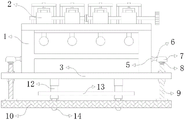
FIG. 1 is a schematic front view of the present invention;
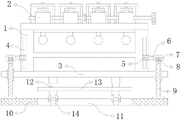
FIG. 2 is a schematic cross-sectional structural view of the present invention;
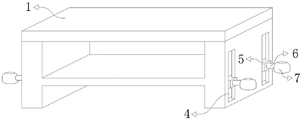
FIG. 3 is a front view of the fixing frame of the present invention;
FIG. 4 is a front view of the first base table of the present invention.
In the figure: 1. a fixed mount; 2. a direct shear apparatus body; 3. a first base table; 4. a T-shaped chute; 5. a T-shaped sliding block; 6. connecting a steel rod; 7. a fixed block; 8. a servo motor; 9. a ball screw; 10. a second base table; 11. a square groove; 12. an electric telescopic rod; 13. a fixing plate; 14. a universal wheel; 15. a bubble level.
Detailed Description
The technical solutions in the embodiments of the present invention will be clearly and completely described below with reference to the drawings in the embodiments of the present invention, and it is obvious that the described embodiments are only a part of the embodiments of the present invention, and not all of the embodiments. All other embodiments, which can be derived by a person skilled in the art from the embodiments given herein without making any creative effort, shall fall within the protection scope of the present invention.
Referring to fig. 1-4, the present invention provides a technical solution: a high accuracy quadruple equal strain direct shear apparatus, includes: a fixed frame 1, a direct shear apparatus body 2, a first base platform 3, a T-shaped sliding chute 4, a T-shaped sliding block 5, a connecting steel rod 6, a fixed block 7, a servo motor 8, a ball screw 9, a second base platform 10, a square groove 11, an electric telescopic rod 12, a fixed plate 13, a universal wheel 14 and a bubble level gauge 15,
the direct shear apparatus comprises a fixed frame 1, wherein a direct shear apparatus body 2 is fixedly mounted at the top of the fixed frame 1, the bottom of the fixed frame 1 is fixedly connected with a first base table 3, and a T-shaped sliding groove 4 is formed in the side wall of the fixed frame 1;
the T-shaped sliding block 5 is arranged on the side wall of the fixing frame 1 in a lifting mode, one side of the T-shaped sliding block 5 is fixedly connected with a connecting steel rod 6, one end of the connecting steel rod 6 is welded with a fixing block 7, a servo motor 8 is fixedly arranged inside the fixing block 7, an output shaft of the servo motor 8 is fixedly connected with a ball screw 9 through a coupler, and meanwhile the bottom end of the ball screw 9 is fixedly connected with a second base table 10;
the second base table 10 is fixedly arranged at the bottom end of the ball screw 9, and a square groove 11 is formed in the top of the second base table 10;
the electric telescopic rod 12 is installed at the bottom of the first base table 3, the bottom end of the electric telescopic rod 12 is fixedly connected with a fixing plate 13, and the bottom of the fixing plate 13 is provided with a universal wheel 14;
and a bubble level 15 which is fitted on the top of the first base table 3, and the bubble level 15 is symmetrically arranged on the top of the first base table 3.
Specifically, as shown in fig. 2 and 3, the number of the T-shaped chutes 4 and the number of the T-shaped sliders 5 are four, the T-shaped chutes 4 and the T-shaped sliders 5 are arranged in one-to-one correspondence, a T-shaped slider 5 is movably mounted inside each T-shaped chute 4, the T-shaped chutes 4 and the T-shaped sliders 5 are symmetrically arranged on the outer walls of the left side and the right side of the fixing frame 1, and the ball screw 9 is limited to a certain extent by the arranged T-shaped chutes 4 and the T-shaped sliders 5, so that the connection relationship between the structures is increased;
specifically, as shown in fig. 2 and 3, the T-shaped sliding block 5 forms a sliding structure with the fixed frame 1 through the T-shaped sliding groove 4, the T-shaped sliding block 5 slides along the inner wall of the T-shaped sliding groove 4, the shape and size of the T-shaped sliding block 5 are matched with the shape and size of the T-shaped sliding groove 4, and the T-shaped sliding block 5 is convenient to move up and down through the arranged T-shaped sliding groove 4, so that the up-and-down movement of a screw rod in the ball screw 9 is adapted;
specifically, as shown in fig. 2, the outer wall of the ball screw 9 is fixedly connected with the first base table 3, the bottom end of the ball screw 9 is fixedly connected with the top of the second base table 10, the first base table 3 and the second base table 10 are movably connected through the ball screw 9, and the movable connection between the first base table 3 and the second base table 10 is facilitated through the arranged ball screw 9, so that the first base table 3 is conveniently adjusted;
specifically, as shown in fig. 1, 2 and 4, the second base table 10 is located right below the first base table 3, and the universal wheel 14 passes through the second base table 10 through the square groove 11, so that the universal wheel 14 passes through the second base table 10 to drive the device to move integrally through the square groove 11;
specifically as shown in fig. 1, fig. 2 and fig. 4, the top end of the electric telescopic rod 12 is fixedly connected with the bottom of the first base table 3, the bottom end of the electric telescopic rod 12 is fixedly connected with the top of the fixing plate 13, the first base table 3, the electric telescopic rod 12 and the fixing plate 13 form an integrated fixing structure, the fixing plate 13 is installed at the bottom of the first base table 3 through the electric telescopic rod 12 capable of ascending and descending, the integrated structure enables connection among all the parts to be tighter, and the device is more solid and durable.
The working principle is as follows: when the high-precision quadruple equal-strain staight-shear apparatus is used, according to the figures 1, 2, 3 and 4, firstly, the electric telescopic rod 12 is started to extend to drive the fixing plate 13 to descend so as to drive the universal wheels 14 to move downwards, and because the universal wheels 14 are abutted to the ground, the second base table 10 is reversely lifted to leave the ground, at this time, the device can be pushed, the device is moved to a place needing to be used under the action of the electric telescopic rod 12, then the device is erected on the ground, the electric telescopic rod 12 is started to contract again, the second base table 10 slowly returns to the ground along with the shortening of the electric telescopic rod 12, the device is stably erected on the ground under the support of the second base table 10, then the position of the air bubble in the air bubble level gauge 15 is observed, if the air bubble is in the middle position, the staight-shear apparatus body 2 can be used immediately, if the air bubble is not in the middle position, the first base table 3 needs to be adjusted, can start servo motor 8 and drive ball screw 9 and rotate, turn into the power of up-and-down motion with the revolving force, T style of calligraphy slider 5 slides from top to bottom along T style of calligraphy spout 4 thereupon, through adjusting four ball screw 9, progressively adjusts the bubble in the bubble spirit level 15 to between two parties, and the back is accomplished in the adjustment, and direct shear appearance body 2 is in the horizontality, can begin the official start-up.
Those not described in detail in this specification are within the skill of the art.
Although embodiments of the present invention have been shown and described, it will be appreciated by those skilled in the art that changes, modifications, substitutions and alterations can be made in these embodiments without departing from the principles and spirit of the utility model, the scope of which is defined in the appended claims and their equivalents.
Claims (6)
1. The utility model provides a high accuracy quadruple direct shear apparatus that meets an emergency, its characterized in that includes:
the direct shear apparatus comprises a fixed frame, a first base table and a second base table, wherein the top of the fixed frame is fixedly provided with a direct shear apparatus body, the bottom of the fixed frame is fixedly connected with the first base table, and the side wall of the fixed frame is provided with a T-shaped sliding groove;
the T-shaped sliding block is arranged on the side wall of the fixing frame in a lifting mode, one side of the T-shaped sliding block is fixedly connected with a connecting steel rod, one end of the connecting steel rod is welded with a fixing block, a servo motor is fixedly arranged inside the fixing block, an output shaft of the servo motor is fixedly connected with a ball screw through a coupler, and meanwhile the bottom end of the ball screw is fixedly connected with a second base table;
the second base table is fixedly arranged at the bottom end of the ball screw, and a square groove is formed in the top of the second base table;
the electric telescopic rod is installed at the bottom of the first base table, the bottom end of the electric telescopic rod is fixedly connected with a fixed plate, and the bottom of the fixed plate is provided with universal wheels;
and the bubble level meters are embedded and installed at the top of the first base platform, and are symmetrically arranged at the top of the first base platform.
2. The high-precision quadruple equal-strain direct shear apparatus according to claim 1, wherein: the quantity of T style of calligraphy spout and the quantity of T style of calligraphy slider are four, and T style of calligraphy spout and T style of calligraphy slider one-to-one setting, and the equal movable mounting in inside of each T style of calligraphy spout has a T style of calligraphy slider, and T style of calligraphy spout and T style of calligraphy slider symmetry set up the left and right sides outer wall of mount.
3. The high-precision quadruple equal-strain direct shear apparatus according to claim 1, wherein: the T-shaped sliding block and the fixing frame form a sliding structure through the T-shaped sliding groove, the T-shaped sliding block slides along the inner wall of the T-shaped sliding groove, and the shape and the size of the T-shaped sliding block are matched with those of the T-shaped sliding groove.
4. The high-precision quadruple equal-strain direct shear apparatus according to claim 1, wherein: the outer wall of the ball screw is fixedly connected with the first base table, the bottom end of the ball screw is fixedly connected with the top of the second base table, and the first base table and the second base table are movably connected through the ball screw.
5. The high-precision quadruple equal-strain direct shear apparatus according to claim 1, wherein: the second base platform is located under the first base platform, and the universal wheel passes through the second base platform through square groove.
6. The high-precision quadruple equal-strain direct shear apparatus according to claim 1, wherein: the top of electric telescopic handle and the bottom fixed connection of first base platform, and electric telescopic handle's bottom and the top fixed connection of fixed plate, and first base platform, electric telescopic handle and fixed plate constitute integration fixed knot and construct, and the fixed plate passes through the bottom at first base platform of installing of electric telescopic handle liftable.
Priority Applications (1)
| Application Number | Priority Date | Filing Date | Title |
|---|---|---|---|
| CN202121959853.XU CN216051065U (en) | 2021-08-19 | 2021-08-19 | A high-precision quadruple constant-strain direct shearing instrument |
Applications Claiming Priority (1)
| Application Number | Priority Date | Filing Date | Title |
|---|---|---|---|
| CN202121959853.XU CN216051065U (en) | 2021-08-19 | 2021-08-19 | A high-precision quadruple constant-strain direct shearing instrument |
Publications (1)
| Publication Number | Publication Date |
|---|---|
| CN216051065U true CN216051065U (en) | 2022-03-15 |
Family
ID=80620504
Family Applications (1)
| Application Number | Title | Priority Date | Filing Date |
|---|---|---|---|
| CN202121959853.XU Expired - Fee Related CN216051065U (en) | 2021-08-19 | 2021-08-19 | A high-precision quadruple constant-strain direct shearing instrument |
Country Status (1)
| Country | Link |
|---|---|
| CN (1) | CN216051065U (en) |
Cited By (1)
| Publication number | Priority date | Publication date | Assignee | Title |
|---|---|---|---|---|
| CN110530739A (en) * | 2019-08-26 | 2019-12-03 | 常熟市徐润机电有限公司 | Full-automatic tetrad strain controlling formula direct shear apparatus |
-
2021
- 2021-08-19 CN CN202121959853.XU patent/CN216051065U/en not_active Expired - Fee Related
Cited By (2)
| Publication number | Priority date | Publication date | Assignee | Title |
|---|---|---|---|---|
| CN110530739A (en) * | 2019-08-26 | 2019-12-03 | 常熟市徐润机电有限公司 | Full-automatic tetrad strain controlling formula direct shear apparatus |
| CN110530739B (en) * | 2019-08-26 | 2024-02-27 | 常熟市徐润机电有限公司 | Full-automatic four-linkage strain control type direct shear apparatus |
Similar Documents
| Publication | Publication Date | Title |
|---|---|---|
| CN114837441B (en) | Wall body positioner for assembled building | |
| CN209397937U (en) | One kind, which builds to build, uses beam regulating instrument | |
| CN113915478B (en) | A high-precision vertical mobile platform device | |
| CN219889213U (en) | Movable tripod leveling bearing platform device | |
| CN213902351U (en) | A new type of building measuring instrument | |
| CN102128676A (en) | Toy noise detection profiling mechanism | |
| CN110514229A (en) | A kind of level device and leveling method measuring instrument of surveying and mapping | |
| CN111059422A (en) | VR locator with quick locate function | |
| CN214747982U (en) | Engineering measurement equipment based on communication tower under sunshine | |
| CN211601945U (en) | Electric power engineering cost construction levelness check out test set | |
| CN223138661U (en) | A plumb bob rack that is easy to erect | |
| CN211477114U (en) | A measuring stick for unmanned aerial vehicle high accuracy aerial survey | |
| CN220870442U (en) | High-precision measuring device for roof steel frame structure | |
| CN115596950B (en) | Measuring device for construction of light source angularly adjustable | |
| CN221860407U (en) | An ancient building wall tilt measurement scanning device | |
| CN222316517U (en) | A device with a stable structure for deformation and precise measurement | |
| CN216923882U (en) | Precise triangular height measuring device | |
| CN223974580U (en) | Soft soil foundation pile deviation correcting device with sensor | |
| CN220039443U (en) | Vertical leveling device for tiles | |
| CN224254740U (en) | Adjusting device for pipe gang saw turning plate mechanism | |
| CN215596943U (en) | Multifunctional engineering measuring device | |
| CN224033419U (en) | Wall perpendicularity detection device for building engineering | |
| CN215066675U (en) | Concrete slump detection device of even vibrations | |
| CN218090407U (en) | Road surface leveling instrument | |
| CN218326935U (en) | Section measuring device for construction |
Legal Events
| Date | Code | Title | Description |
|---|---|---|---|
| GR01 | Patent grant | ||
| GR01 | Patent grant | ||
| CF01 | Termination of patent right due to non-payment of annual fee |
Granted publication date: 20220315 |
|
| CF01 | Termination of patent right due to non-payment of annual fee |