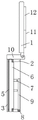
Wired earplug convenient to store
Technical Field
The utility model relates to a containing device, in particular to a wired earplug convenient to contain.
Background
The wired earphone is a wired earphone device, generally comprises an earphone main body and a storage bag, is used for storing the wired earphone, is widely used for listening music and watching videos, and is generally matched with electronic equipment for use.
The existing wired earplug is inconvenient to store, is usually manually wound on a hand and then placed in a storage bag or a storage box, so that the existing wired earplug is inconvenient to store, easy to wind and inconvenient to use, and therefore a wired earplug device which is not easy to wind and convenient to store is needed.
Disclosure of Invention
The utility model aims to solve the problems that the existing wired earplugs are inconvenient to store, are usually wound on hands manually and then are placed in a storage bag or a storage box, so that the wired earplugs are inconvenient to store, easy to wind and inconvenient to use.
In order to achieve the purpose, the utility model provides the following technical scheme:
a wired earplug convenient to store comprises a box cover, an upper half box body, a lower half box body and an earplug body, wherein bearings are fixed on opposite surfaces of the upper half box body and the lower half box body, a rotating block is fixed on the other side of each bearing, the rotating block is movably connected inside the upper half box body, a limiting column is fixed on one side, away from the lower half box body, of the rotating block, the limiting column is positioned inside the upper half box body, a groove is formed in one side, away from the bearing, of the upper half box body, a limiting rod is rotatably connected inside the groove, one end of the limiting rod is movably connected with one end of the limiting column, the earplug body is wound on the surface of the limiting column, the earplug body is movable inside the upper half box body, connecting blocks are fixed on one sides of the upper half box body and the lower half box body, the box cover is rotatably connected on the surface of the connecting blocks, a protective layer is arranged on one side, close to the upper half box body, and a placing groove is formed in the position, corresponding to the limiting rod, the gag lever post activity is in the inside of standing groove, and the magnet is embedded to one side surface that first half box body and lid contact.
Preferably: the number of the limiting columns is two, and the two limiting columns are distributed in an annular array mode by taking the axis of the rotating block as an array center.
Preferably: the number of the bearings is two, and the surface of the rotating block between the two bearings is provided with anti-skid grains.
Preferably: the magnetism of the magnet on the upper half box body is opposite to that of the magnet on the box cover.
Preferably: the bearing is a thrust bearing.
Due to the adoption of the technical scheme, the utility model has the following advantages:
through setting up the turning block, a bearing, spacing post, gag lever post and lid, during the operation, at first with gag lever post and spacing post separation, then place the intermediate position of earplug body between two spacing posts, then with the one end and the spacing post contact of gag lever post, then place on the gag lever post with one hand and carry out spacingly to it, then another hand rotates the turning block, make it drive two spacing post rotations, spacing post rotates and drives the earplug body around the inside of first box body, then cover the lid on first box body, it is firm to be connected lid and first box body through magnet, reached and conveniently accomodate the earplug body, difficult cause the earplug body to twine and be difficult to the detached problem.
Drawings
Fig. 1 is a front view of a wired earplug for easy stowing.
Fig. 2 is a left side cross-sectional view of a corded earplug pair in the position of a restraining post for ease of stowing.
Fig. 3 is a perspective view of a wired earplug for easy storage.
Detailed Description
The technical solution in the embodiments of the present invention will be clearly and completely described below with reference to the accompanying drawings in the embodiments of the present invention.
Referring to fig. 1 to 3, in the embodiment of the utility model, the wired earplug convenient to store comprises a box cover 1, an upper half box body 2, a lower half box body 3 and an earplug body 4, wherein bearings 5 are fixed on opposite surfaces of the upper half box body 2 and the lower half box body 3, the number of the bearings 5 is two, anti-slip threads are arranged on the surface of a rotating block 6 located between the two bearings 5, so that the rotating block 6 can rotate manually and prevent hand slip, the bearings 5 are thrust bearings, the rotating block 6 is fixed on the other side of each bearing 5, the rotating block 6 is movably connected inside the upper half box body 2, limiting columns 7 are fixed on one side of the rotating block 6, which is far away from the lower half box body 3, the number of the limiting columns 7 is two, the two limiting columns 7 are distributed in an annular array by taking the axis of the rotating block 6 as an array center, so that the earplug body can be conveniently wound on the surface of the limiting columns 7, and the limiting columns 7 are located inside the upper half box body 2.
The utility model discloses a spacing structure of earphone, including first box body 2, bearing 5, recess 8, gag lever post 9, gag lever post 7, earplug body 4, the inside rotation of recess 8 is connected with gag lever post 9, gag lever post 9 one end and the one end swing joint of spacing post 7, earplug body 4 encircles on the surface of spacing post 7, earplug body 4 activity is in the inside of first box body 2, first box body 2 all is fixed with connecting block 10 with one side of second box body 3, the rotation of lid 1 is connected on the surface of connecting block 10, lid 1 is close to one side of first box body 2 and is provided with protective layer 11, protective layer 11 has seted up standing groove 12 corresponding to the position of gag lever post 9, gag lever post 9 activity is in the inside of standing groove 12, one side surface that first box body 2 and lid 1 contact is embedded to have magnet 13, the magnetism of the magnet 13 on first box body 2 is opposite with the magnetism of magnet 13 on the lid 1, connect first box body 2 and lid 1 through magnet 13.