CN216031656U - Preparation facilities of environment-friendly insulation concrete - Google Patents
Preparation facilities of environment-friendly insulation concrete Download PDFInfo
- Publication number
- CN216031656U CN216031656U CN202121812468.2U CN202121812468U CN216031656U CN 216031656 U CN216031656 U CN 216031656U CN 202121812468 U CN202121812468 U CN 202121812468U CN 216031656 U CN216031656 U CN 216031656U
- Authority
- CN
- China
- Prior art keywords
- roller
- fixedly arranged
- push rod
- electric push
- concrete
- Prior art date
- Legal status (The legal status is an assumption and is not a legal conclusion. Google has not performed a legal analysis and makes no representation as to the accuracy of the status listed.)
- Active
Links
- 239000004567 concrete Substances 0.000 title claims abstract description 50
- 238000002360 preparation method Methods 0.000 title claims abstract description 21
- 238000009413 insulation Methods 0.000 title description 3
- 238000003756 stirring Methods 0.000 claims abstract description 36
- 238000003860 storage Methods 0.000 claims description 16
- 230000007246 mechanism Effects 0.000 claims description 12
- 238000004321 preservation Methods 0.000 claims description 4
- 239000000463 material Substances 0.000 claims description 3
- 239000002994 raw material Substances 0.000 abstract description 11
- 238000000034 method Methods 0.000 abstract description 5
- 230000008569 process Effects 0.000 abstract description 4
- 238000004140 cleaning Methods 0.000 description 3
- 239000010426 asphalt Substances 0.000 description 2
- 230000000694 effects Effects 0.000 description 2
- 238000007790 scraping Methods 0.000 description 2
- XLYOFNOQVPJJNP-UHFFFAOYSA-N water Substances O XLYOFNOQVPJJNP-UHFFFAOYSA-N 0.000 description 2
- 230000009471 action Effects 0.000 description 1
- 239000000654 additive Substances 0.000 description 1
- 239000012615 aggregate Substances 0.000 description 1
- 239000011384 asphalt concrete Substances 0.000 description 1
- 230000009286 beneficial effect Effects 0.000 description 1
- 239000004568 cement Substances 0.000 description 1
- 238000010276 construction Methods 0.000 description 1
- 230000007547 defect Effects 0.000 description 1
- 238000005265 energy consumption Methods 0.000 description 1
- 230000006872 improvement Effects 0.000 description 1
- 239000000203 mixture Substances 0.000 description 1
- 238000012986 modification Methods 0.000 description 1
- 230000004048 modification Effects 0.000 description 1
- 238000005303 weighing Methods 0.000 description 1
Images



Landscapes
- Preparation Of Clay, And Manufacture Of Mixtures Containing Clay Or Cement (AREA)
Abstract
The utility model discloses a preparation device of environment-friendly heat-insulating concrete, which comprises a bottom plate, wherein an electric push rod is fixedly arranged at one end of the bottom plate, a fixed table is fixedly arranged at one end of the bottom plate, which is far away from the electric push rod, a roller is arranged above the middle part of the bottom plate, and a first bearing is arranged in the middle part of one end, which is close to the electric push rod, of the roller. According to the utility model, when concrete is manufactured and poured out, the electric push rod drives the support column and the roller to incline towards one side of the discharge port, the concrete flows out of the discharge port and enters the bearing vehicle, the stirring rotating shaft can drive the stirring blades to rotate, so that the concrete is stirred more uniformly, the roller is also more convenient to clean, when raw materials are required to be filled into the roller, the joint and the joint are clamped through threads, the roller rotates to process the raw materials into the concrete, and the heat-insulating layer effectively ensures that the temperature of the concrete is kept within a set value range during processing, so that the quality of the produced concrete is improved.
Description
Technical Field
The utility model relates to the technical field of concrete preparation, in particular to a preparation device of environment-friendly heat-insulating concrete.
Background
The concrete preparation equipment is equipment for weighing and mixing cement, gravel aggregate, water, additives and the like according to a certain mixing proportion to prepare a concrete mixture, and in recent years, on the basis of two original drop-out and forced basic structural forms, a planetary mixer, a drum mixer, a mixer with a vibration device, a sound wave mixer, a drop-out forced mixer and the like are successively provided, and the novel mixing main machines have new breakthroughs in the aspects of reducing energy consumption, improving mixing quality, adaptability to various aggregates and the like.
Current concrete preparation facilities possess the heat preservation function very few to after concrete mixing accomplishes, the concrete is emptyd unclean, and the concrete spills easily at the in-process of empting, causes the harm to the environment, to above problem, needs to improve current equipment.
The prior patent (patent publication No. CN 212000486U) discloses a recycled asphalt concrete waterproof bonding material preparation device, which comprises a device main body, supporting rods, a base and a shell cover, wherein the two sides of the bottom of the device main body are fixedly connected with the supporting rods, the top of the device main body is fixedly connected with the shell cover, the middle part of the bottom of the shell cover is fixedly connected with a telescopic rod, the bottom of the telescopic rod is movably connected with a rotary table, the bottom of the rotary table is fixedly connected with a stirring mechanism, when the stirring mechanism is driven by the rotary table to stir, scraping knives on the stirring mechanism are unfolded towards two sides under the action of a movable shaft, so that recycled asphalt attached to the inner wall of an inner barrel is cleaned through the scraping knives, resources can be better utilized, the cleaning effect of the device is greatly improved, locking bolts can well mount and dismount the stirring mechanism, thereby better stirring asphalt can be stirred after the stirring mechanism is replaced, has wide development prospect in the future. However, in the new patent, the concrete preparation device has no heat preservation function, the stirring effect is poor, the cleaning process is complex, and the improvement is needed.
SUMMERY OF THE UTILITY MODEL
The utility model aims to solve the defects in the prior art and provides a preparation device of environment-friendly heat-insulating concrete.
In order to achieve the purpose, the utility model adopts the following technical scheme: the environment-friendly heat-insulating concrete preparation device comprises a bottom plate, wherein an electric push rod is fixedly arranged at one end of the bottom plate, a fixed table is fixedly arranged at one end, away from the electric push rod, of the bottom plate, a roller is arranged above the middle part of the bottom plate, a first bearing is arranged in the middle of one end, close to the electric push rod, of the roller, a discharge hole is formed in the lower end of the side wall, close to the electric push rod, of the roller, a feed hole is formed in the upper end of the side wall, close to the fixed table, of the roller, a connector is fixedly arranged in the feed hole, and a second bearing is fixedly arranged in the middle of the inner wall of one end, away from the first bearing, of the roller;
a first cavity chamber is arranged in the electric push rod, a first placing platform is fixedly arranged at the inner bottom end of the first cavity chamber, a first motor is fixedly arranged on the first placing platform, the output end of the first motor is fixedly connected with a stirring rotating shaft, a support column is fixedly arranged at the upper end of the side wall of the electric push rod, which is close to the stirring rotating shaft, is rotatably connected with a first bearing, a through hole is arranged in the support column, and the stirring rotating shaft passes through the through hole and is rotatably connected with a second bearing;
the fixed station is internally provided with a second cavity chamber and a third cavity chamber, the bottom end of the second cavity chamber is fixedly provided with a second placing platform, a second motor is fixedly arranged on the second placing platform, the output end of the second motor is fixedly connected with a main rotating shaft, one end of the main rotating shaft, far away from the second motor, is fixedly connected with a roller, the bottom end of the third cavity chamber is fixedly provided with a third placing platform, the third placing platform is fixedly provided with a controller, the top end of the fixed station is fixedly provided with a placing platform, the placing platform is fixedly provided with a storage box, the storage box is close to the middle part of the side wall of the roller, and one end of the conveying pipe, far away from the storage box, is fixedly provided with a joint.
As a further description of the above technical solution:
the bearing vehicle is arranged above the middle part of the bottom plate, and a plurality of roller mechanisms are fixedly arranged at the bottom end of the bearing vehicle.
As a further description of the above technical solution:
and the inner wall of the roller is provided with a heat insulation layer.
As a further description of the above technical solution:
a plurality of stirring blades are fixedly arranged on the stirring rotating shaft.
As a further description of the above technical solution:
the top end of the storage box is fixedly provided with a feeding tank.
As a further description of the above technical solution:
the interface is detachably connected with the joint through threads.
As a further description of the above technical solution:
the bottom of the front end face of the electric push rod is provided with a loudspeaker, the lower end of the side wall of the electric push rod, which is close to the roller, is fixedly provided with an infrared emitter, and the lower end of the side wall of the fixed platform, which is close to the roller, is fixedly provided with an infrared receiver.
As a further description of the above technical solution:
the infrared transmitter and the infrared receiver are electrically connected with the controller.
The utility model has the following beneficial effects:
1. according to the utility model, the electric push rod, the support column, the roller, the stirring rotating shaft, the stirring blade and the discharge hole are arranged, when the concrete is manufactured and poured out, the electric push rod moves downwards to drive the support column and the roller to incline towards one side of the discharge hole, so that the collection rate of concrete preparation is improved, the stirring rotating shaft can drive the stirring blade to rotate, the concrete is stirred more uniformly, and the roller is also cleaned more conveniently.
2. The utility model is provided with a roller, a discharge port, a bearing vehicle, an infrared emitter, a controller and a roller mechanism, when the concrete is poured out after being made, the concrete flows out of the discharge port and enters the bearing vehicle, when the concrete blocks the light emitted by the infrared emitter, the controller controls the loudspeaker to make a sound, and the bearing vehicle is dragged by the roller mechanism to convey the concrete to a required place, thereby effectively avoiding the concrete from spilling and protecting the ground cleanness of a construction place.
3. The utility model is provided with a joint, a connector, a conveying pipe and a roller, wherein one end of the conveying pipe is fixedly provided with the joint, when raw materials need to be filled into the roller, the joint and the connector are clamped through threads, the raw materials can enter the roller through the conveying pipe, after the raw materials are filled, the joint is disassembled from the connector, the roller rotates to process the raw materials into concrete, and the concrete processing is more efficient due to the arrangement of a detachable structure.
4. The utility model is provided with the roller and the heat-insulating layer, and the heat-insulating layer effectively ensures that the temperature of the concrete is kept within the range of a set value during processing, thereby improving the quality of the produced concrete.
Drawings
FIG. 1 is a schematic perspective view of an apparatus for preparing environment-friendly heat-insulating concrete according to the present invention;
FIG. 2 is a front sectional view of an apparatus for preparing environment-friendly heat-insulating concrete according to the present invention;
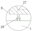
FIG. 3 is an enlarged view at B in FIG. 2;
fig. 4 is an enlarged view of a portion a in fig. 2.
Illustration of the drawings:
1. a base plate; 2. an electric push rod; 3. a fixed table; 4. a drum; 5. a first bearing; 6. a discharge port; 7. a feed inlet; 8. an interface; 9. a second bearing; 10. a first hollow chamber; 11. a first placement platform; 12. a first motor; 13. a stirring rotating shaft; 14. a support pillar; 15. a through hole; 16. a second hollow chamber; 17. a third hollow chamber; 18. a second placement platform; 19. a second motor; 20. a main rotating shaft; 21. a third placement platform; 22. a controller; 23. a platform is placed; 24. a material storage box; 25. a delivery pipe; 26. a joint; 27. a load-bearing vehicle; 28. a roller mechanism; 29. a heat-insulating layer; 30. a stirring blade; 31. a feed tank; 32. a speaker; 33. an infrared emitter; 34. an infrared receiver.
Detailed Description
The technical solutions in the embodiments of the present invention will be clearly and completely described below with reference to the drawings in the embodiments of the present invention, and it is obvious that the described embodiments are only a part of the embodiments of the present invention, and not all of the embodiments. All other embodiments, which can be derived by a person skilled in the art from the embodiments given herein without making any creative effort, shall fall within the protection scope of the present invention.
In the description of the present invention, it should be noted that the terms "center", "upper", "lower", "left", "right", "vertical", "horizontal", "inner", "outer", etc., indicate orientations or positional relationships based on the orientations or positional relationships shown in the drawings, and are only for convenience of description and simplicity of description, but do not indicate or imply that the device or element being referred to must have a particular orientation, be constructed and operated in a particular orientation, and thus, should not be construed as limiting the present invention; the terms "first," "second," and "third" are used for descriptive purposes only and are not to be construed as indicating or implying relative importance, and furthermore, unless otherwise explicitly stated or limited, the terms "mounted," "connected," and "connected" are to be construed broadly and may be, for example, fixedly connected, detachably connected, or integrally connected; can be mechanically or electrically connected; they may be connected directly or indirectly through intervening media, or they may be interconnected between two elements. The specific meanings of the above terms in the present invention can be understood in specific cases to those skilled in the art.
Referring to fig. 1-4, one embodiment of the present invention is provided: the environment-friendly heat-insulating concrete preparation device comprises a bottom plate 1, wherein an electric push rod 2 is fixedly arranged at one end of the bottom plate 1, a fixed table 3 is fixedly arranged at one end, away from the electric push rod 2, of the bottom plate 1, a roller 4 is arranged above the middle part of the bottom plate 1, a first bearing 5 is arranged in the middle of one end, close to the electric push rod 2, of the roller 4, a discharge hole 6 is formed in the lower end of the side wall, close to the electric push rod 2, of the roller 4, a feed inlet 7 is formed in the upper end of the side wall, close to the fixed table 3, of the roller 4, a connector 8 is fixedly arranged in the feed inlet 7, and a second bearing 9 is fixedly arranged in the middle of the inner wall of one end, away from the first bearing 5, of the roller 4;
a first hollow chamber 10 is arranged inside the electric push rod 2, a first placing platform 11 is fixedly arranged at the inner bottom end of the first hollow chamber 10, a first motor 12 is fixedly arranged on the first placing platform 11, the output end of the first motor 12 is fixedly connected with a stirring rotating shaft 13, a supporting column 14 is fixedly arranged at the upper end of the side wall of the electric push rod 2 close to the stirring rotating shaft 13, the supporting column 14 is rotatably connected with the first bearing 5, a through hole 15 is arranged inside the supporting column 14, and the stirring rotating shaft 13 penetrates through the through hole 15 to be rotatably connected with the second bearing 9;
inside second cavity 16 and the third cavity 17 of being provided with of fixed station 3, the 16 bottom mounting of second cavity sets up second place the platform 18, the fixed second motor 19 that is provided with on second place the platform 18, second motor 19's output fixedly connected with owner pivot 20, the one end and the cylinder 4 fixed connection of second motor 19 are kept away from to main pivot 20, the 17 bottom mounting of third cavity is provided with third place the platform 21, the fixed controller 22 that is provided with on third place the platform 21, the fixed platform 23 that falls that is provided with in top of fixed station 3, the fixed storage case 24 that is provided with on the platform 23 that falls, storage case 24 is close to the lateral wall middle part fixedly connected with conveyer pipe 25 of cylinder 4, the fixed joint 26 that is provided with in one end that storage case 24 was kept away from to conveyer pipe 25.
The working principle is as follows: when the raw material is filled into the roller 4, the joint 26 is clamped with the interface 8 through threads, the raw material enters the roller 4 through the conveying pipe 25, after the raw material is filled, the joint 26 is detached from the interface 8, the roller 4 rotates to process the raw material into concrete, the stirring rotating shaft 13 can drive the stirring blade 30 to rotate, so that the concrete is stirred more uniformly, when the concrete is manufactured and needs to be poured out, the electric push rod 2 moves downwards to drive the support column 14 and the roller 4 to incline towards the side of the discharge port 6, the concrete flows out of the discharge port 6 to enter the bearing vehicle 27, when the concrete blocks light emitted by the infrared emitter 33, the controller 22 controls the loudspeaker 32 to make sound, the bearing vehicle 27 is dragged to convey the concrete to a needed place through the roller mechanism 28, when the roller 4 is cleaned, clear water is added, and the stirring rotating shaft 13 drives the stirring blade 30 to rotate, cleaning of the drum 4 is achieved.
Finally, it should be noted that: although the present invention has been described in detail with reference to the foregoing embodiments, it will be apparent to those skilled in the art that modifications may be made to the embodiments or portions thereof without departing from the spirit and scope of the utility model.
Claims (8)
1. The utility model provides a preparation facilities of environment-friendly heat preservation concrete, includes bottom plate (1), its characterized in that: an electric push rod (2) is fixedly arranged at one end of the bottom plate (1), a fixed table (3) is fixedly arranged at one end, away from the electric push rod (2), of the bottom plate (1), a roller (4) is arranged above the middle of the bottom plate (1), a first bearing (5) is arranged in the middle of one end, close to the electric push rod (2), of the roller (4), a discharge hole (6) is formed in the lower end of the side wall, close to the electric push rod (2), of the roller (4), a feed hole (7) is formed in the upper end of the side wall, close to the fixed table (3), of the roller (4), a connector (8) is fixedly arranged in the feed hole (7), and a second bearing (9) is fixedly arranged in the middle of the inner wall, away from the first bearing (5), of one end, away from the first bearing (5), of the roller (4);
a first cavity chamber (10) is arranged inside the electric push rod (2), a first placing platform (11) is fixedly arranged at the inner bottom end of the first cavity chamber (10), a first motor (12) is fixedly arranged on the first placing platform (11), the output end of the first motor (12) is fixedly connected with a stirring rotating shaft (13), a supporting column (14) is fixedly arranged at the upper end of the side wall, close to the stirring rotating shaft (13), of the electric push rod (2), the supporting column (14) is rotatably connected with the first bearing (5), a through hole (15) is formed inside the supporting column (14), and the stirring rotating shaft (13) penetrates through the through hole (15) to be rotatably connected with the second bearing (9);
a second cavity chamber (16) and a third cavity chamber (17) are arranged inside the fixed table (3), a second placing platform (18) is fixedly arranged at the bottom end of the second cavity chamber (16), a second motor (19) is fixedly arranged on the second placing platform (18), a main rotating shaft (20) is fixedly connected with the output end of the second motor (19), one end, far away from the second motor (19), of the main rotating shaft (20) is fixedly connected with the roller (4), a third placing platform (21) is fixedly arranged at the bottom end of the third cavity chamber (17), a controller (22) is fixedly arranged on the third placing platform (21), a storage platform (23) is fixedly arranged at the top end of the fixed table (3), a storage box (24) is fixedly arranged on the storage platform (23), and a conveying pipe (25) is fixedly connected with the middle part of the side wall of the storage box (24) close to the roller (4), and a joint (26) is fixedly arranged at one end of the conveying pipe (25) far away from the material storage box (24).
2. The preparation device of the environment-friendly heat-insulating concrete according to claim 1, characterized in that: the bottom plate (1) middle part top is provided with bears car (27), bear car (27) bottom mounting and be provided with a plurality of gyro wheel mechanisms (28).
3. The preparation device of the environment-friendly heat-insulating concrete according to claim 1, characterized in that: and a heat-insulating layer (29) is arranged on the inner wall of the roller (4).
4. The preparation device of the environment-friendly heat-insulating concrete according to claim 1, characterized in that: and a plurality of stirring blades (30) are fixedly arranged on the stirring rotating shaft (13).
5. The preparation device of the environment-friendly heat-insulating concrete according to claim 1, characterized in that: the top end of the storage box (24) is fixedly provided with a feed tank (31).
6. The preparation device of the environment-friendly heat-insulating concrete according to claim 1, characterized in that: the interface (8) is detachably connected with the joint (26) through threads.
7. The preparation device of the environment-friendly heat-insulating concrete according to claim 1, characterized in that: the electric push rod (2) is characterized in that a loudspeaker (32) is arranged at the bottom of the front end face of the electric push rod (2), an infrared emitter (33) is fixedly arranged at the lower end of the side wall of the electric push rod (2) close to the roller (4), and an infrared receiver (34) is fixedly arranged at the lower end of the side wall of the fixed platform (3) close to the roller (4).
8. The preparation device of the environment-friendly heat-insulating concrete according to claim 7, characterized in that: the infrared transmitter (33) and the infrared receiver (34) are both electrically connected with the controller (22).
Priority Applications (1)
| Application Number | Priority Date | Filing Date | Title |
|---|---|---|---|
| CN202121812468.2U CN216031656U (en) | 2021-08-05 | 2021-08-05 | Preparation facilities of environment-friendly insulation concrete |
Applications Claiming Priority (1)
| Application Number | Priority Date | Filing Date | Title |
|---|---|---|---|
| CN202121812468.2U CN216031656U (en) | 2021-08-05 | 2021-08-05 | Preparation facilities of environment-friendly insulation concrete |
Publications (1)
| Publication Number | Publication Date |
|---|---|
| CN216031656U true CN216031656U (en) | 2022-03-15 |
Family
ID=80619113
Family Applications (1)
| Application Number | Title | Priority Date | Filing Date |
|---|---|---|---|
| CN202121812468.2U Active CN216031656U (en) | 2021-08-05 | 2021-08-05 | Preparation facilities of environment-friendly insulation concrete |
Country Status (1)
| Country | Link |
|---|---|
| CN (1) | CN216031656U (en) |
-
2021
- 2021-08-05 CN CN202121812468.2U patent/CN216031656U/en active Active
Similar Documents
| Publication | Publication Date | Title |
|---|---|---|
| CN213829687U (en) | Foam concrete production equipment | |
| CN210206508U (en) | A processing agitating unit for microlite panel | |
| CN214954713U (en) | Temperature control device for concrete | |
| CN213918938U (en) | Recycled concrete processing is with portable stirring casting machine | |
| CN218834203U (en) | Heat preservation mortar agitating unit convenient to inside is clean | |
| CN218748530U (en) | A dust collection device for mixer for producing concrete | |
| CN217581286U (en) | Concrete vibrating equipment | |
| CN217621345U (en) | Mix concrete additive liquid solid mixing arrangement | |
| CN215282625U (en) | Be used for cement mixer for municipal road engineering construction | |
| CN212684521U (en) | Latex foaming machine is used in production of latex pillow | |
| CN214136674U (en) | Concrete mixing device for road construction | |
| CN213699644U (en) | Foaming agent solution preparation device | |
| CN206855755U (en) | A kind of construction site mixer | |
| CN114055625A (en) | Electronic ceramic material production and processing equipment | |
| CN222550658U (en) | A raw material mixing mechanism for producing environmentally friendly thermal insulation and aeration materials | |
| CN216372793U (en) | Concrete preparation equipment for improving performance of concrete | |
| CN217047059U (en) | A stirring dispersion devices for polyurethane raw materials | |
| CN216760352U (en) | Stirring equipment for lightweight plastering gypsum mortar | |
| CN112388830A (en) | GRC board processing is with pouring equipment | |
| CN220922842U (en) | Stirring device | |
| CN218838188U (en) | Low viscosity high performance concrete is with concrete agitating unit | |
| CN224167325U (en) | Environment-friendly biological pesticide suspending agent preparation device | |
| CN217829720U (en) | Heating and stirring device for graphite anode production | |
| CN217220990U (en) | Preparation device of anti-cracking waste tire rubber powder composite modified asphalt mixture | |
| CN221999685U (en) | A mixing device for producing phosphogypsum-based materials for road base construction |
Legal Events
| Date | Code | Title | Description |
|---|---|---|---|
| GR01 | Patent grant | ||
| GR01 | Patent grant |