Abrasive wheel cutting machine with controllable cutting depth
Technical Field
The utility model relates to the technical field of cutting machines, in particular to a grinding wheel cutting machine with a controllable cutting depth.
Background
The abrasive wheel cutting machine is a common electric tool in daily life, and can cut materials such as metal square flat tubes and angle irons, and the abrasive wheel of the abrasive wheel cutting machine is brittle, has high rotating speed and is dangerous to a certain extent when in use, so that the knowledge of correctly using the abrasive wheel cutting machine needs to be mastered to better use the abrasive wheel cutting machine, although the existing abrasive wheel cutting machine can meet part of work requirements.
But the inconvenient, the complicated and inconvenient problem of control cutting knife depth of cut of cutting knife swing process operation of cutting knife angle swing of current abrasive wheel cutting machine cutting knife.
Disclosure of Invention
The utility model aims to provide a grinding wheel cutting machine with controllable cutting depth, and aims to solve the problem that the angle of a cutting knife provided in the background technology is inconvenient to swing.
In order to achieve the purpose, the utility model provides the following technical scheme: a grinding wheel cutting machine with controllable cutting depth comprises a first box body, a second box body and a cutting knife, wherein the first box body is rotatably connected with the outer wall of the second box body, the cutting knife is arranged inside the second box body, and a swinging structure is arranged inside the first box body;
the swing structure comprises a turntable, a first screw, a trough plate, a connecting rod and a round head plate;
it is a plurality of the end and the second box fixed connection of head board, the round bar of head board tip and the inside spout sliding connection of frid are a plurality of the tip and the supporting seat of frid rotate to be connected, the both ends of connecting rod rotate with the frid to be connected, the right side frid and a tip sliding connection of first screw rod, the other end and the carousel fixed connection of first screw rod, the outer wall and the first box threaded connection of first screw rod.
Preferably, the inner wall of the first box body is fixedly connected with the supporting seat, the first box body is fixedly connected with the lower end of the clamp body, and the sliding groove of the second box body is connected with the outer walls of the sliding blocks in a sliding mode.
Preferably, the tail end of the sliding block is fixedly connected with the second frame, the second frame is fixedly connected with the outer wall of the second motor, the outer end of an output shaft of the second motor is fixedly connected with the input end of the gear set, the output end of the gear set is rotatably connected with the long shaft through a belt and a belt pulley, the long shaft is fixedly connected with the inner wall of the cutting knife, and two ends of the long shaft are rotatably connected with the second frame through bearings.
Preferably, a moving structure is installed inside the second box body;
the moving structure comprises a rack, a worm gear, a worm, a first motor and a first frame;
the inner side of the rack is meshed with a worm wheel, the worm wheel is meshed with a worm, the end of the worm wheel is rotatably connected with the first frame, two ends of the worm are rotatably connected with the first frame through bearings, the tail end of the worm is fixedly connected with an output shaft of the first motor, and the tail end of the rack is fixedly connected with the sliding block.
Preferably, the upper ends of the first motor and the first frame are fixedly connected with the second box body, and an output shaft of the first motor is rotatably connected with the first frame through a bearing.
Compared with the prior art, the utility model has the beneficial effects that: according to the abrasive wheel cutting machine with the controllable cutting depth, through the matching among the rotary table, the first screw, the groove plates, the connecting rod and the round head plates, the rotary table is rotated to drive the first screw to rotate, the first screw rotates to push the groove plates on the two sides to swing, the groove plates on the two sides are in a parallel swinging state through the connecting rod, the groove plates on the two sides swing in parallel to drive the round head plates to swing, when the required angle is reached, the rotation of the rotary table is stopped, and the problem that the angle of a cutting knife is inconvenient to swing is solved;
through the matching among the circular head plate, the first motor, the second motor, the rotary table and the second box body, the circular head plate is driven to swing through the rotation of the rotary table, so that the second box body is in an inclined state, the second box body is inclined to drive the cutting knife to incline, and then angle cutting can be carried out by starting the second motor and the first motor, so that the problem that the operation of the cutting knife in the swinging process is complex is solved;
through first motor, the worm wheel, the cooperation between rack and the slider, first motor rotates and drives the worm and rotate, the worm rotates and drives the worm wheel and rotate, the worm wheel rotates and drives rack removal, at this moment, rack removal drives the second frame through the slider and removes, the cutting knife just cuts the work piece on the clamp body, treat to reach required depth of cut alright with the rotation that stops first motor, the depth of cut of control cutting knife is realized through first motor pivoted number of turns, the inconvenient problem of the depth of cut of control cutting knife has been solved.
Drawings
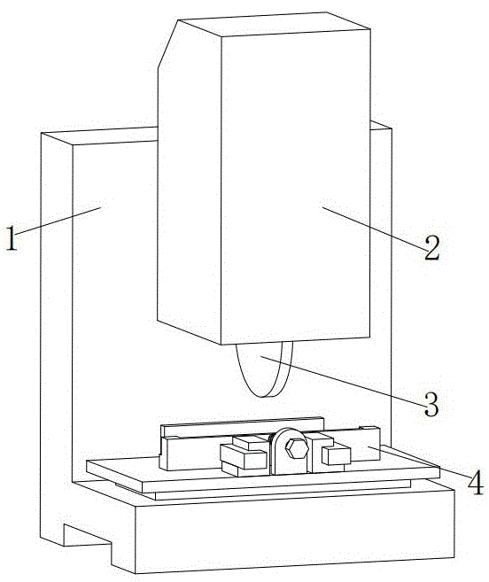
FIG. 1 is a schematic structural view of the present invention;
FIG. 2 is a schematic view of a connection structure of the first box, the second box and the clamping block in FIG. 1;
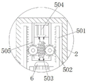
FIG. 3 is a schematic view of a connection structure of the first motor, the first frame and the worm wheel in FIG. 2;
fig. 4 is a schematic view of a connection structure of the rotary disc, the first screw and the first box in fig. 2.
In the figure: 1. the cutting device comprises a first box body, a second box body, a cutting knife, a first clamping body, a second clamping body, a moving structure, a rack 501, a rack 502, a worm gear, a worm 503, a worm 504, a first motor 505, a first frame 6, a second motor 7, a swinging structure 701, a turntable 702, a first screw rod 703, a groove plate 704, a connecting rod 705, a circular head plate 8, a long shaft 9, a gear set 10, a second frame 11, a sliding block 12, a belt 13, a belt pulley 14 and a supporting seat.
Detailed Description
The technical solutions in the embodiments of the present invention will be clearly and completely described below with reference to the drawings in the embodiments of the present invention, and it is obvious that the described embodiments are only a part of the embodiments of the present invention, and not all of the embodiments. All other embodiments, which can be derived by a person skilled in the art from the embodiments given herein without making any creative effort, shall fall within the protection scope of the present invention.
Referring to fig. 1-4, the present invention provides a technical solution: a grinding wheel cutting machine with controllable cutting depth comprises a first box body 1, a second box body 2 and a cutting knife 3, wherein the outer wall of the first box body 1 is rotatably connected with the outer wall of the second box body 2, the second box body 2 can rotate on the first box body 1, the cutting knife 3 is arranged inside the second box body 2, a swing structure 7 is arranged inside the first box body 1, the swing structure 7 comprises a turntable 701, a first screw 702, a groove plate 703, a connecting rod 704 and a round head plate 705, the tail ends of the round head plates 705 are fixedly connected with the second box body 2, the round head plate 705 can swing together with the second box body 2, a round rod at the end part of the round head plate 705 is in sliding connection with a sliding groove inside the groove plate 703, the groove plate 703 swings to drive the round head plate to swing, the end parts of the groove plates 703 are rotatably connected with a supporting seat 14, the groove plate 703 can swing on the supporting seat 14, two ends of the connecting rod 704 are rotatably connected with the groove plate 703, and the connecting rod 704 enables the groove plates 703 on the left side and the right side to swing synchronously, the right side trough plate 703 is connected with one end of the first screw 702 in a sliding way, the first screw 702 moves to drive the trough plate 703 to swing, the other end of the first screw 702 is fixedly connected with the turntable 701, the outer wall of the first screw 702 is connected with the first box body 1 in a threaded way, the first screw 702 can be driven to rotate by rotating the turntable 701, the inner wall of the first box body 1 is fixedly connected with the supporting seat 14, the first box body 1 is fixedly connected with the lower end of the clamp body 4, the clamp body 4 can fix a workpiece, the chute of the second box body 2 is connected with the outer walls of a plurality of sliding blocks 11 in a sliding way, the sliding blocks 11 can move on the second box body 2, the tail ends of the sliding blocks 11 are fixedly connected with the second frame 10, the sliding blocks 11 can move together with the second frame 10, the second frame 10 is fixedly connected with the outer wall of the second motor 6, the outer end of the output shaft of the second motor 6 is fixedly connected with the input end of the gear set 9, the second motor 6 can drive the gear set 9 to rotate, the output end of the gear set 9 is rotatably connected with the long shaft 8 through a belt 12 and a belt pulley 13, the output end of the gear set 9 drives the long shaft 8 to rotate, the long shaft 8 is fixedly connected with the inner wall of the cutting knife 3, the long shaft 8 can rotate together with the cutting knife 3, two ends of the long shaft 8 are rotatably connected with the second frame 10 through bearings, the long shaft 8 rotates on the second frame 10, and a user can meet working requirements according to actual conditions to select models of the second motor 6 and the first motor 504.
The second box body 2 is internally provided with a moving structure 5, the moving structure 5 comprises a rack 501 and a worm gear 502, the inner sides of the racks 501 are meshed with the worm wheel 502, the worm wheel 502 rotates to drive the racks 501 to move, the worm wheels 502 are meshed with the worm 503, the worm wheel 503 rotates to drive the worm wheel 502 to rotate, the end of the worm wheel 502 is rotatably connected with the first frame 505, two ends of the worm 503 are rotatably connected with the first frame 505 through bearings, the worm wheel 502 and the worm 503 are fixed in rotating positions, the tail end of the worm 503 is fixedly connected with an output shaft of the first motor 504, the first motor 504 can drive the worm 503 to rotate, the tail end of the rack 501 is fixedly connected with the sliding block 11, the sliding block 11 can be driven by the movement of the rack 501 to move, the upper ends of the first frame 505 and the first motor 504 are fixedly connected with the second box 2, and the output shaft of the first motor 504 is rotatably connected with the first frame 505 through bearings.
Before cutting, two options of vertical cutting and inclined cutting are provided, when inclined cutting is needed, firstly, a turntable 701 is rotated to drive a first screw 702 to rotate, the first screw 702 rotates to push two side groove plates 703 to swing, at the moment, the two side groove plates 703 are in a parallel swinging state through a connecting rod 704, the two side groove plates 703 are in a parallel swinging state to drive a circular head plate 705 to swing, when the required angle is reached, the rotation of the turntable 701 is stopped, a second box body 2 is in an inclined state through rotating the turntable 701 to drive the circular head plate 705 to swing, the second box body 2 is inclined to drive a cutting knife 3 to incline, vertical processing does not need to rotate the turntable 701, after a processing angle is determined, a second motor 6 is started to drive the cutting knife 3 to rotate, then a first motor 504 is started, the first motor 504 rotates to drive a worm 503 to rotate, the worm 503 rotates to drive a worm wheel 502 to rotate, and drives a rack 501 to move, at this moment, the rack 501 moves to drive the second frame 10 to move through the slider 11, then the cutting knife 3 cuts the workpiece on the fixture body 4, the rotation of the first motor 504 can be stopped when the required cutting depth is reached, and the cutting depth of the cutting knife 3 can be controlled through the number of rotating circles of the first motor 504.
In the description of the present invention, it is to be understood that the terms "coaxial", "bottom", "one end", "top", "middle", "other end", "upper", "one side", "top", "inner", "front", "center", "both ends", and the like, indicate orientations or positional relationships based on those shown in the drawings, and are only for convenience of description and simplicity of description, and do not indicate or imply that the referenced device or element must have a particular orientation, be constructed and operated in a particular orientation, and thus, are not to be construed as limiting the present invention.
In the present invention, unless otherwise expressly specified or limited, the terms "mounted," "disposed," "connected," "secured," "screwed" and the like are to be construed broadly, e.g., as meaning fixedly connected, detachably connected, or integrally formed; can be mechanically or electrically connected; the terms may be directly connected or indirectly connected through an intermediate, and may be communication between two elements or interaction relationship between two elements, unless otherwise specifically limited, and the specific meaning of the terms in the present invention will be understood by those skilled in the art according to specific situations.
Although embodiments of the present invention have been shown and described, it will be appreciated by those skilled in the art that changes, modifications, substitutions and alterations can be made in these embodiments without departing from the principles and spirit of the utility model, the scope of which is defined in the appended claims and their equivalents.