SUMMERY OF THE UTILITY MODEL
An object of the utility model is to provide a fastener with tensile function of pulling out to solve the problem that proposes in the above-mentioned background art.
In order to achieve the above object, the utility model provides a following technical scheme:
the utility model provides a fastener with anti-drawing function, includes the base, the top of base evenly runs through and is provided with a plurality of connecting holes, the top fixedly connected with fixing base of base, the top sliding connection of base has the slider, one side of slider is provided with the spring, the equal fixedly connected with fixture in top of fixing base and slider, fixture includes down the fastener, the outer wall of fastener articulates down has last fastener, the outer wall of going up the fastener runs through and is provided with first bolt, first bolt and last fastener rotate to be connected, the top of fastener and the department that corresponds of first bolt set up threaded hole down, the screw hole is connected with first bolt cooperation.
As a further aspect of the present invention: the top of the base is fixedly connected with a sliding rod through two mounting blocks, the sliding block is sleeved on the sliding rod in a sliding mode, the spring sleeve is arranged outside the sliding rod in a sleeved mode, the mounting blocks corresponding to one end of the spring abut against each other, and the other end of the spring is fixedly connected with the outer wall of the sliding block.
As a further aspect of the present invention: the sliding block is positioned between the spring and the fixed seat.
As a further aspect of the present invention: go up the top of fastener and run through and be provided with hand and twist the bolt, hand is twisted the bolt and is gone up fastener threaded connection, the bottom of hand is twisted the bolt and is rotated and be connected with the arc piece, the inner wall of going up the fastener is seted up with the groove of accomodating of arc piece looks adaptation.
As a further aspect of the present invention: the top of the arc piece is located two guide rods fixedly connected with two bilateral symmetry positions of the hand-screwed bolt, two guide holes matched with the guide rods are formed in the top of the upper wire clamp in a penetrating mode, and the top ends of the guide holes are located in the corresponding guide holes.
As a further aspect of the present invention: the inboard fixedly connected with second arc card strip of fastener down, the inboard fixedly connected with first arc card strip of arc piece.
Compared with the prior art, the beneficial effects of the utility model are that:
1. the utility model discloses in the use, when the cable received and violently dragged, the slider can slide on the slide bar to compress the spring, thereby utilize the deformation of spring to absorb the impact force in the twinkling of an eye that the cable received by the centre gripping department, in order to avoid the insulating outer wall of cable the damaged phenomenon of fracture to appear, played good tensile to the cable and pulled out and the guard action.
2. The utility model discloses a setting of bolt is twisted with the hand to the arc piece, when the cable diameter is less than the through-hole between fastener and the last fastener, can move down through rotating the hand and twist bolt drive arc piece, in order to utilize fastener to fix the centre gripping to the cable under the cooperation of arc piece, thereby be applicable to not unidimensional cable, through the setting of first arc card strip and second arc card strip, when carrying out the centre gripping to the cable, first arc card strip can imbed in the cable insulation skin with second arc card strip, thereby play good fixed action.
Drawings
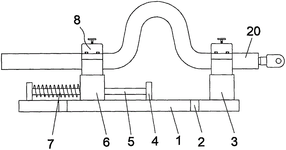
Fig. 1 is a structural schematic diagram of a wire clamp with a pulling-resistant function.
Fig. 2 is a schematic structural diagram of a clamping mechanism in a wire clamp with a pulling-resistant function.
Fig. 3 is a structural diagram of a first arc-shaped clamping strip in the wire clamp with the anti-pulling function.
The clamping device comprises a base 1, a connecting hole 2, a fixing seat 3, an installation block 4, a sliding rod 5, a sliding block 6, a spring 7, a clamping mechanism 8, a lower wire clamp 9, an upper wire clamp 10, a threaded hole 11, a first bolt 12, a containing groove 13, an arc-shaped sheet 14, a hand-screwed bolt 15, a guide rod 16, a guide hole 17, a first arc-shaped clamping strip 18, a second arc-shaped clamping strip 19 and a cable 20.
Detailed Description
In order to make the technical problem, technical scheme and beneficial effect that the utility model will solve more clearly understand, will combine the embodiment below, it is right to the utility model discloses go on further detailed description. It should be understood that the specific embodiments described herein are merely illustrative of the invention and are not intended to limit the invention.
It will be understood that when an element is referred to as being "secured to" or "disposed on" another element, it can be directly on the other element or be indirectly on the other element. When an element is referred to as being "connected to" another element, it can be directly connected to the other element or be indirectly connected to the other element.
It will be understood that the terms "upper", "lower", "front", "rear", "left", "right", "vertical", "horizontal", "top", "bottom", "inner", "outer", and the like, are used in the orientation or positional relationship indicated in the drawings for convenience in describing the invention and to simplify the description, and do not indicate or imply that the device or element so referred to must have the orientation, configuration, and operation specified in the specification and therefore should not be construed as limiting the invention.
Furthermore, the terms "first", "second", "third" are used for descriptive purposes only and are not to be construed as indicating or implying relative importance or implicitly indicating the number of technical features indicated. Thus, a feature defined as "first" or "second" may explicitly or implicitly include one or more of that feature.
Please refer to fig. 1-3, in the embodiment of the present invention, an anti-pulling wire clamp includes a base 1, the top of the base 1 is uniformly provided with a plurality of connecting holes 2, the top fixedly connected with fixing base 3 of the base 1, the top sliding connected with slider 6 of the base 1, one side of the slider 6 is provided with a spring 7, the top of the fixing base 3 and the slider 6 is fixedly connected with a clamping mechanism 8, the clamping mechanism 8 includes a lower wire clamp 9, the outer wall of the lower wire clamp 9 is hinged with an upper wire clamp 10, the outer wall of the upper wire clamp 10 is provided with a first bolt 12 in a penetrating manner, the first bolt 12 is rotatably connected with the upper wire clamp 10, the top of the lower wire clamp 9 and the corresponding position of the first bolt 12 are provided with a threaded hole 11, and the threaded hole 11 is connected with the first bolt 12 in a matching manner.
The top of the base 1 is fixedly connected with a sliding rod 5 through two mounting blocks 4, the sliding block 6 is sleeved on the sliding rod 5 in a sliding mode, the spring 7 is sleeved outside the sliding rod 5, the mounting blocks 4 corresponding to one end of the spring 7 are abutted, and the other end of the spring 7 is fixedly connected with the outer wall of the sliding block 6.
Through the setting of slide bar 5, can effectual improvement slider 6 gliding stability, play good guide effect to spring 7 simultaneously, appear the skew when avoiding spring 7 atress compression.
The slide 6 is located between the spring 7 and the holder 3.
Go up the top of fastener 10 and run through and be provided with hand screwed bolt 15, hand screwed bolt 15 and last fastener 10 threaded connection, the bottom swivelling joint of hand screwed bolt 15 has arc piece 14, the inner wall of going up fastener 10 is seted up the groove 13 of accomodating with arc piece 14 looks adaptation.
Through the setting of arc piece 14 and hand screw bolt 15, when the cable diameter is less than the through-hole between fastener 9 and the last fastener 10, can move down through rotating hand screw bolt 15 drive arc piece 14 to utilize 14 cooperation fastener 9 of arc piece to fix the centre gripping to the cable, thereby be applicable to not unidimensional cable.
The top of the arc-shaped piece 14 is positioned on two sides of the hand-screwed bolt 15 and is symmetrically and fixedly connected with two guide rods 16, the top of the upper wire clamp 10 is provided with two guide holes 17 matched with the guide rods 16 in a penetrating manner, and the top ends of the guide holes 17 are positioned in the corresponding guide holes 17.
By means of the matching of the guide hole 17 and the guide rod 16, the arc-shaped piece 14 can be well guided, and therefore the arc-shaped piece 14 is prevented from rotating along with the screwing of the bolt 15.
The inner side of the lower wire clamp 9 is fixedly connected with a second arc-shaped clamping strip 19, and the inner side of the arc-shaped piece 14 is fixedly connected with a first arc-shaped clamping strip 18.
Through the setting of first arc card strip 18 and second arc card strip 19, when carrying out the centre gripping to the cable, first arc card strip 18 and second arc card strip 19 can imbed in the cable insulation skin to play good fixed action.
The utility model discloses a theory of operation is:
the utility model discloses when using, fix the one end of installing the connection nose on the cable earlier on the fixture 8 at 3 tops of fixing base, later buckle the cable, fix the cable on the fixture 8 at 6 tops of slider again, and guarantee that the cable length between two fixtures 8 is greater than the spacing distance of fixing base 3 and slider 6, when the cable receives and violently pulls, slider 6 can slide on slide bar 5, and compress spring 7, thereby utilize the deformation of spring 7 to absorb the impact force in the twinkling of an eye that the cable received by the centre gripping department, in order to avoid the damaged phenomenon of fracture to appear in the insulating outer wall of cable, good tensile drawing and guard action have been played the cable.
The utility model discloses a setting of bolt 15 is twisted with the hand to arc piece 14, when the cable diameter is less than the through-hole between fastener 9 and the last fastener 10, can twist bolt 15 drive arc piece 14 through the rotation hand and move down, in order to utilize 14 cooperation fastener 9 of arc piece to fix the centre gripping to the cable, thereby be applicable to not unidimensional cable, through the setting of first arc card strip 18 with second arc card strip 19, when carrying out the centre gripping to the cable, first arc card strip 18 can imbed in the cable insulation cover with second arc card strip 19, thereby play good fixed action.
Although the present invention has been described in detail with reference to the foregoing embodiments, it will be apparent to those skilled in the art that modifications may be made to the embodiments or portions thereof without departing from the spirit and scope of the invention.