Special-shaped piece processing combination frock
Technical Field
The utility model belongs to the technical field of the frock, concretely relates to dysmorphism processing combination frock.
Background
The tooling is technological equipment and is a general name of tools used in the production process, the tooling comprises a fixture, a die, a cutter and the like, in the machining process, the workpiece is machined, the tooling is generally required to be used for positioning the workpiece, at present, in the machining production of a special-shaped part such as a gear, the gear is clamped by a combined fixture, the position of the gear is continuously changed when the gear is machined, but the existing combined fixture for clamping the gear still has the defects when the gear is used, an inner hole of the gear cannot be firmly fastened after being extruded by the fixture, the gear is easy to loosen after the outer wall of the gear is subjected to the cutting force of the cutter, and in the machining process of a wide gear, the fixture cannot drive the gear to transversely move, so that the machining range of the gear is small.
SUMMERY OF THE UTILITY MODEL
An object of the utility model is to provide a dysmorphism processing combination frock to solve current modular fixture who is used for pressing from both sides tight gear behind the hole of extrusion gear, can not guarantee that the gear firmly fastens, the gear is easy not hard up, and anchor clamps can't drive the gear and carry out lateral shifting, the little problem of range of processing of gear.
In order to achieve the above object, the utility model provides a following technical scheme: the utility model provides a dysmorphism piece processing combination frock, includes first mounting panel, but horizontal slip's second mounting panel is installed to one side of first mounting panel, install rotatable first installation axle and second installation axle on the lateral wall of first mounting panel and second mounting panel respectively, first installation axle and second installation epaxial fixed cover respectively are equipped with first clamping piece and second clamping piece, the centre gripping has the gear between first clamping piece and the second clamping piece, install the jack catch device on the first clamping piece.
Preferably, the bottom of first mounting panel is connected with the bottom plate, the second mounting panel slides and sets up in the top of bottom plate, the mount pad is installed to the bottom of bottom plate, the inside of mount pad is provided with first lead screw drive assembly, first lead screw drive assembly includes the first slider of slidable, be connected with the connecting block between first slider and the bottom plate, the spout has been seted up at the top of mount pad, the connecting block slides and sets up in the spout.
Preferably, the hole has been seted up to the inside of gear, the jack catch device is including two jack catchs and two second screw drive subassemblies, two that the symmetry is installed on first clamping piece lateral wall the jack catch all is located the inboard of hole, two mounting grooves have been seted up to the inside symmetry of first clamping piece, every second screw drive subassembly all includes installs second gag lever post on the mounting groove inner wall, rotates and sets up in the inside second lead screw of mounting groove and close soon through the screw thread and connect the second slider on the second lead screw, every the outside of a second gag lever post is located to the equal sliding sleeve of second slider to and be connected with the connecting rod between the jack catch.
Preferably, the first screw rod transmission assembly further comprises a first limiting rod arranged inside the mounting seat and a first screw rod rotatably arranged inside the mounting seat, and the first sliding block is connected to the first screw rod in a screwing mode through threads and is sleeved outside the first limiting rod in a sliding mode.
Preferably, a transverse electric push rod is installed at the top of the bottom plate, and the movable end of the electric push rod is connected to one side wall of the second installation plate.
Preferably, a side wall mounting of mount pad has first motor, and the drive shaft of first motor and the one end fixed connection of first lead screw, a side wall mounting of second mounting panel has the second motor, and the drive shaft and the second installation axle fixed connection of second motor, install two third motors on the outer wall of first clamping piece, and the drive shaft of every third motor all with the tip fixed connection of a second lead screw.
Compared with the prior art, the utility model, following beneficial effect has:
(1) the utility model discloses a with the first clamping piece of last installation of jack catch device, first clamping piece fixed mounting is in first installation epaxially to set up second installation axle and second clamping piece, the jack catch device is with the hole extrusion back of gear, presss from both sides tightly in the both sides of gear through first clamping piece and second clamping piece, makes the gear firmly fastened, makes it difficult not hard up at the in-process of cutting, has guaranteed the machining precision of gear.
(2) Based on first installation axle and second installation axle construction, through installing first installation axle and second installation axle on the bottom plate to with bottom plate slidable mounting on the mount pad, drive the bottom plate through the lead screw and remove, thereby make the clamping piece drive gear lateral shifting, enlarged the range of processing of gear, make this combination frock can centre gripping wide gear process.
Drawings
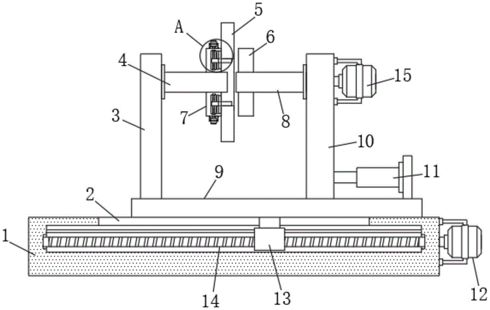
Fig. 1 is a schematic structural view of the present invention;
FIG. 2 is an enlarged view taken at A in FIG. 1;
FIG. 3 is an external view of the present invention;
in the figure: 1. a mounting seat; 2. a chute; 3. a first mounting plate; 4. a first mounting shaft; 5. a gear; 6. a second clip; 7. a first clip piece; 8. a second mounting shaft; 9. a base plate; 10. a second mounting plate; 11. an electric push rod; 12. a first motor; 13. a first slider; 14. a first lead screw; 15. a second motor; 16. an inner bore; 17. a claw; 18. a second lead screw; 19. a third motor; 20. and (4) mounting the groove.
Detailed Description
The technical solutions in the embodiments of the present invention will be described clearly and completely with reference to the accompanying drawings in the embodiments of the present invention, and it is obvious that the described embodiments are only some embodiments of the present invention, not all embodiments. Based on the embodiments in the present invention, all other embodiments obtained by a person skilled in the art without creative work belong to the protection scope of the present invention.
Referring to fig. 1-3, the present invention provides the following technical solutions: a combined tool for machining a special-shaped part comprises a first mounting plate 3, a second mounting plate 10 capable of sliding horizontally is mounted on one side of the first mounting plate 3, a rotatable first mounting shaft 4 and a rotatable second mounting shaft 8 are mounted on one side wall of the first mounting plate 3 and one side wall of the second mounting plate 10 respectively, a first clamping piece 7 and a second clamping piece 6 are fixedly sleeved on the first mounting shaft 4 and the second mounting shaft 8 respectively, a gear 5 is clamped between the first clamping piece 7 and the second clamping piece 6, a clamping jaw device is mounted on the first clamping piece 7, specifically, an inner hole 16 of the gear 5 is extruded by the clamping jaw device, one side wall of the gear 5 is abutted against the first clamping piece 7, an electric push rod 11 is started to push the second mounting plate 10 to approach towards the first mounting plate 3 until the second clamping piece 6 is abutted against the other side wall of the gear 5, and the gear 5 is clamped by the second clamping piece 6 and the first clamping piece 7, the gear 5 is firmly fastened, so that the gear is not easy to loosen in the cutting process, and the machining precision of the gear 5 is ensured.
Further, the bottom of first mounting panel 3 is connected with bottom plate 9, second mounting panel 10 slides and sets up in the top of bottom plate 9, mount pad 1 is installed to the bottom of bottom plate 9, the inside of mount pad 1 is provided with first lead screw drive assembly, first lead screw drive assembly includes slidable first slider 13, be connected with the connecting block between first slider 13 and the bottom plate 9, spout 2 has been seted up at the top of mount pad 1, the connecting block slides and sets up in spout 2, specifically, slide through first lead screw drive assembly drive bottom plate 9, and then drive second clamping piece 6 and 7 clamping gear 5 lateral shifting of first clamping piece, gear 5's processing scope has been enlarged, make this combination frock can the big gear 5 of centre gripping width process.
Furthermore, an inner hole 16 is formed in the gear 5, the jaw device comprises two jaws 17 and two second lead screw transmission assemblies which are symmetrically installed on one side wall of the first clamping piece 7, the two jaws 17 are located on the inner side of the inner hole 16, two installation grooves 20 are symmetrically formed in the first clamping piece 7, each second lead screw transmission assembly comprises a second limiting rod installed on the inner wall of the installation groove 20, a second lead screw 18 which is rotatably arranged in the installation groove 20 and a second sliding block which is connected to the second lead screw 18 through threads in a screwing mode, each second sliding block is sleeved outside one second limiting rod in a sliding mode and connected with a connecting rod between one jaw 17, specifically, one end face, connected with the jaws 17, of each connecting rod is flush with the side wall of the first clamping piece 7, two third motors 19 are simultaneously started to drive the two second lead screws 18 to rotate, and the two second sliding blocks drive the two jaws 17 to move in opposite directions or move towards each other under the action of the second limiting rods And the inner hole 16 of the gear 5 is squeezed or loosened, the gear 5 is fastened during squeezing, and the gear 5 can be taken down after loosening.
Specifically, first lead screw drive assembly still sets up in the inside first lead screw 14 of mount pad 1 including installing in the inside first gag lever post of mount pad 1 and rotating, first slider 13 closes soon through the screw thread and connects on first lead screw 14 to the outside of first gag lever post is located to the slip cap, and is concrete, during the gear 5 that the machining width is big, start first motor 12 and drive first lead screw 14 and rotate, make first slider 13 drive bottom plate 9 lateral shifting under the effect of first gag lever post, realize the lateral shifting that gear 5 adds man-hour.
It is worth mentioning that a transverse electric push rod 11 is mounted on the top of the bottom plate 9, a movable end of the electric push rod 11 is connected to a side wall of the second mounting plate 10, and the electric push rod 11 is used for driving the second mounting plate 10 to move on the surface of the bottom plate 9.
Further, a side wall of the mounting seat 1 is provided with a first motor 12, a driving shaft of the first motor 12 is fixedly connected with one end of the first lead screw 14, a side wall of the second mounting plate 10 is provided with a second motor 15, the driving shaft of the second motor 15 is fixedly connected with the second mounting shaft 8, the outer wall of the first clamping piece 7 is provided with two third motors 19, the driving shaft of each third motor 19 is fixedly connected with the end of one second lead screw 18, after the second clamping piece 6 and the first clamping piece 7 clamp the gear 5, the gear starts the second motor 15 to drive the second mounting shaft 8 to rotate in the processing process, and further drives the second clamping piece 6, the first clamping piece 7, the gear 5 and the first mounting shaft 4 to synchronously rotate, so that the circumferential processing of the gear 5 is realized.
Although embodiments of the present invention have been shown and described, it will be appreciated by those skilled in the art that changes, modifications, substitutions and alterations can be made in these embodiments without departing from the principles and spirit of the invention, the scope of which is defined in the appended claims and their equivalents.