CN215997950U - Reactor blockage cleaning device - Google Patents
Reactor blockage cleaning device Download PDFInfo
- Publication number
- CN215997950U CN215997950U CN202122221366.XU CN202122221366U CN215997950U CN 215997950 U CN215997950 U CN 215997950U CN 202122221366 U CN202122221366 U CN 202122221366U CN 215997950 U CN215997950 U CN 215997950U
- Authority
- CN
- China
- Prior art keywords
- nozzle
- base
- sleeve
- pipe
- shower nozzle
- Prior art date
- Legal status (The legal status is an assumption and is not a legal conclusion. Google has not performed a legal analysis and makes no representation as to the accuracy of the status listed.)
- Expired - Fee Related
Links
- 238000004140 cleaning Methods 0.000 title claims abstract description 12
- XLYOFNOQVPJJNP-UHFFFAOYSA-N water Substances O XLYOFNOQVPJJNP-UHFFFAOYSA-N 0.000 claims abstract description 24
- 239000000126 substance Substances 0.000 abstract description 3
- 230000000694 effects Effects 0.000 abstract description 2
- 239000007921 spray Substances 0.000 description 11
- 239000002351 wastewater Substances 0.000 description 3
- 238000000576 coating method Methods 0.000 description 2
- 239000007788 liquid Substances 0.000 description 2
- 238000005507 spraying Methods 0.000 description 2
- 101100080052 Arabidopsis thaliana NIP2 gene Proteins 0.000 description 1
- 230000009286 beneficial effect Effects 0.000 description 1
- 238000012824 chemical production Methods 0.000 description 1
- 239000011248 coating agent Substances 0.000 description 1
- 150000001875 compounds Chemical class 0.000 description 1
- 238000007599 discharging Methods 0.000 description 1
- 238000010438 heat treatment Methods 0.000 description 1
- 239000002184 metal Substances 0.000 description 1
- 230000004048 modification Effects 0.000 description 1
- 238000012986 modification Methods 0.000 description 1
- 229920002401 polyacrylamide Polymers 0.000 description 1
- 238000004321 preservation Methods 0.000 description 1
- 239000007787 solid Substances 0.000 description 1
- 238000003756 stirring Methods 0.000 description 1
- 239000004094 surface-active agent Substances 0.000 description 1
Images



Landscapes
- Cleaning By Liquid Or Steam (AREA)
Abstract
The utility model discloses a reation kettle plug cleaning device relates to chemical industry equipment technical field, including rotatory nozzle, shower nozzle support piece, high-pressure water pump, rotatory nozzle pass through the water pipe intercommunication, shower nozzle support piece is used for supporting rotatory nozzle, rotatory nozzle includes shower nozzle pipe, base, nozzle, high-pressure water pump, shower nozzle pipe, base, nozzle communicate in proper order, the nozzle with the base rotates to be connected, 2 are no less than to the quantity of nozzle, the base with the shower nozzle pipe rotates to be connected, the pivot of base is perpendicular with the horizontal plane, the utility model discloses a clearance that is used for reation kettle's discharge gate and cauldron bottom has advantages such as the clearance does not need to observe reation kettle internal conditions when having the clearance and does not have the dead angle, clearance, can solve manual clearance mode cleaning efficiency low, the poor problem of effect.
Description
Technical Field
The utility model relates to a chemical industry equipment technical field specifically is a reation kettle plug cleaning device.
Background
The reaction kettle is a common chemical production device, has the functions of stirring, heating, heat preservation, pressure maintaining and the like, and is commonly used for producing liquid chemicals such as surfactants, coatings and the like.
When a reaction kettle is used for producing high-solid-content products such as coating and the like and high-molecular compounds such as polyacrylamide and the like, a discharge port of the reaction kettle is often blocked due to the fact that the products are thick, and a large amount of solid or semisolid residues are attached to the bottom of the reaction kettle and need to be cleaned; at present main clearance mode is through the handheld dedicated clearance instrument of operating personnel, inserts reation kettle from the feed inlet and inside carries out manual clearance, because inside darker, is difficult to observe the jam condition, hardly the clean up because reation kettle.
SUMMERY OF THE UTILITY MODEL
The utility model aims to provide a: the utility model provides a reation kettle plug cleaning device has the advantage at clearance fast, the comprehensive no dead angle of clearance to solve the problem that manual clearance mode clearance efficiency is low, the effect is poor.
The utility model adopts the technical scheme as follows:
the utility model provides a reation kettle plug cleaning device, includes rotatory nozzle, shower nozzle support piece, high pressure water pump, rotatory nozzle pass through the water pipe intercommunication, shower nozzle support piece is used for supporting rotatory nozzle, rotatory nozzle includes shower nozzle pipe, base, nozzle, high pressure water pump, shower nozzle pipe, base, nozzle communicate in proper order, the nozzle with the base rotates to be connected, 2 are no less than to the quantity of nozzle, the base with the shower nozzle pipe rotates to be connected, the pivot and the horizontal plane of base are perpendicular.
Preferably, the nozzle support member comprises a flange, a first sleeve, a second sleeve, the flange is arranged at the upper end of the first sleeve, the second sleeve is positioned inside the first sleeve, the first sleeve and the second sleeve are fixedly connected, and the upper end and the lower end of the first sleeve are communicated.
Preferably, a plurality of nozzles are arranged on the side surface of the nozzle.
Preferably, the nozzle guide pipe passes through the second sleeve.
Preferably, the lower end of the spray head guide pipe is provided with a handle.
To sum up, owing to adopted above-mentioned technical scheme, the beneficial effects of the utility model are that:
(1) through setting up high pressure water pump and rotatory nozzle, spout high pressure water flow from the nozzle on the rotatory nozzle, promote the shower nozzle simultaneously and continuously rotate, can insert rotatory nozzle and utilize high pressure water flow to clear up from reation kettle's discharge gate department, simultaneously through the height of the handle adjustment nozzle on the shower nozzle pipe, can clear up reation kettle's discharge gate and reation kettle bottom comprehensively, owing to adopted the rotatory nozzle of liftable, basically do not have the dead angle during the clearance, need not to confirm through observing reation kettle inside whether clean up, the utility model discloses the mode that can replace artifical shovel to clear up reation kettle, improved cleaning efficiency greatly.
(2) The rotary spray nozzle is arranged at the discharge port of the reaction kettle, and then the inside and the discharge port of the reaction kettle are cleaned in an all-round way by adjusting the height of the rotary spray nozzle through a handle;
(3) the nozzle is rotatably connected with the base, the nozzle opening of the nozzle is positioned on the side surface of the base, and the reaction force of the sprayed water flow can be utilized to push the spray head to rotate automatically, so that dead angles of high-pressure water flow spraying are greatly reduced.
Drawings
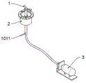
Fig. 1 is a perspective view of the present invention.
FIG. 2 is a structural view of a rotary showerhead and a showerhead support.
FIG. 3 is a schematic view of the connection between the showerhead conduits and the base.
FIG. 4 is a schematic view of the connection of the showerhead conduits to the spray nozzles.
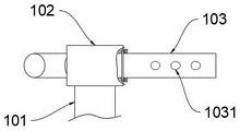
Fig. 5 is a structural view of the nozzle.
The labels in the figure are: 1. rotating the spray head; 2. a showerhead support member; 3. a high pressure water pump; 101. a nozzle guide; 102. a base; 103. a nozzle; 201. a flange; 202. a first sleeve; 203. a second sleeve; 1011. a handle; 1031. and (4) a nozzle.
Detailed Description
In order to make the objects, technical solutions and advantages of the present invention more clearly understood, the following detailed description of the present invention is made with reference to the accompanying drawings and examples, and it should be understood that the specific examples described herein are only for the purpose of explaining the present invention and are not intended to limit the present invention.
As shown in fig. 1-2, a cleaning device for reactor blockage comprises a rotary nozzle 1, a nozzle support 2, and a high pressure water pump 3, wherein the high pressure water pump 3 is an ATL25 type water pump, the maximum water pressure is 25MPa, the high pressure water pump 3 and the rotary nozzle 1 are communicated by a pressure-resistant metal hose, the nozzle support 2 comprises a flange 201, a first sleeve 202, a second sleeve 203, and a flange 201 is arranged at the upper end of the first sleeve 202, the flange 201 is used for connecting with a flange at the discharge port of the reactor, the second sleeve 203 is arranged in the first sleeve 202, the first sleeve 202 and the second sleeve 203 are fixedly connected, the axes of the first sleeve 202 and the second sleeve 203 are coincident, the upper end and the lower end of the first sleeve 202 are communicated for supporting the rotary nozzle 1, the rotary nozzle 1 comprises a nozzle guide pipe 101, a base 102 and a nozzle 103, the high pressure water pump 3, the nozzle guide pipe 101, the base 102 and the nozzle 103 are sequentially communicated, the nozzle guide pipe 101 passes through the second sleeve 203, and the nozzle guide pipe 101 slides relative to the sleeve 203, and the lower end of the nozzle guide pipe 101 is provided with a handle 1011 for adjusting the height of the nozzle guide pipe 101.
As shown in fig. 3, a thrust bearing is provided at the connection between the base 102 and the nozzle guide 101, and the base 102 is rotatably connected to the nozzle guide 101 by the thrust bearing, and the rotation axis of the base 102 is perpendicular to the horizontal plane.
As shown in fig. 2, 4 and 5, a thrust bearing is arranged at the connection part of the nozzle 103 and the base 102, the nozzle 103 and the base 102 are rotatably connected through the thrust bearing, the number of the nozzles 103 is 3, the nozzles 103 are arranged in a central symmetry manner by taking the spray head conduit 101 as a center, 3 spray orifices 1031 are arranged on the side surface of the nozzle 103, and the included angle between the axis of each spray orifice 1031 and the axis of the nozzle 103 is 30 degrees.
The working principle is as follows: before cleaning the reaction kettle, firstly discharging liquid in the reaction kettle through a discharge hole of the reaction kettle, then adjusting an included angle between a nozzle 1031 and a horizontal plane to be 45 degrees downwards in an inclined manner, spraying high-pressure water flow in the downwards inclined direction, connecting a flange 201 with a flange of the discharge hole of the reaction kettle, then placing a waste water barrel right below a first sleeve 202 for collecting waste water, then starting a high-pressure water pump 3 to spray the high-pressure water flow out of the nozzle 1031 and push a nozzle 103 to drive a base 102 to rotate around a nozzle guide pipe 101, so that the high-pressure water flow fully washes the discharge hole and the kettle bottom of the reaction kettle, removes blockages at the bottom and the discharge hole of the reaction kettle, and falls into the waste water barrel from an opening at the lower end of the first sleeve 202; when the shower nozzle is washed, the height of the rotary shower nozzle 1 can be adjusted through the handle 1011, so that the blockages with different heights can be conveniently cleared.
On the basis of the above embodiment, the number of the nozzles 103 can be adjusted between 2 to 4, only the nozzles 103 need to be kept centrosymmetric, the number of the nozzles 1031 can be properly adjusted between 2 to 6, the axes of the nozzles 1031 on a single nozzle 103 need to be kept parallel, and the included angle between the nozzle 1031 and the axis of the nozzle 103 needs to be kept consistent, so that the rotary spray head 1 can stably rotate.
The above description is only exemplary of the present invention and should not be taken as limiting the scope of the present invention, as any modifications, equivalents, improvements and the like made within the spirit and principles of the present invention are intended to be included within the scope of the present invention.
Claims (5)
1. The utility model provides a reation kettle plug cleaning device, characterized in that, includes rotatory nozzle (1), shower nozzle support piece (2), high pressure water pump (3), rotatory nozzle (1) lead to pipe intercommunication, shower nozzle support piece (2) are used for supporting rotatory nozzle (1), rotatory nozzle (1) is including shower nozzle pipe (101), base (102), nozzle (103), high pressure water pump (3), shower nozzle pipe (101), base (102), nozzle (103) communicate in proper order, nozzle (103) with base (102) rotate to be connected, 2 are no less than in the quantity of nozzle (103), base (102) with shower nozzle pipe (101) rotate to be connected, the pivot of base (102) is perpendicular with the horizontal plane.
2. The reactor blockage cleaning device according to claim 1, wherein the nozzle support (2) comprises a flange (201), a first sleeve (202), a second sleeve (203), the flange (201) is arranged at the upper end of the first sleeve (202), the second sleeve (203) is positioned inside the first sleeve (202), the first sleeve (202) and the second sleeve (203) are fixedly connected, and the upper end and the lower end of the first sleeve (202) are communicated.
3. The reactor blockage removing device according to claim 1, wherein the side of the nozzle (103) is provided with a plurality of nozzles (1031).
4. The reactor blockage removal apparatus as claimed in claim 2, wherein the nozzle guide pipe (101) passes through the second sleeve (203).
5. The reactor blockage removal apparatus as claimed in claim 2, wherein the lower end of the nozzle guide pipe (101) is provided with a handle (1011).
Priority Applications (1)
| Application Number | Priority Date | Filing Date | Title |
|---|---|---|---|
| CN202122221366.XU CN215997950U (en) | 2021-09-14 | 2021-09-14 | Reactor blockage cleaning device |
Applications Claiming Priority (1)
| Application Number | Priority Date | Filing Date | Title |
|---|---|---|---|
| CN202122221366.XU CN215997950U (en) | 2021-09-14 | 2021-09-14 | Reactor blockage cleaning device |
Publications (1)
| Publication Number | Publication Date |
|---|---|
| CN215997950U true CN215997950U (en) | 2022-03-11 |
Family
ID=80531644
Family Applications (1)
| Application Number | Title | Priority Date | Filing Date |
|---|---|---|---|
| CN202122221366.XU Expired - Fee Related CN215997950U (en) | 2021-09-14 | 2021-09-14 | Reactor blockage cleaning device |
Country Status (1)
| Country | Link |
|---|---|
| CN (1) | CN215997950U (en) |
Cited By (1)
| Publication number | Priority date | Publication date | Assignee | Title |
|---|---|---|---|---|
| CN116902501A (en) * | 2023-06-25 | 2023-10-20 | 苏州贝彩纳米科技有限公司 | Anti-blocking structure for sludge treatment |
-
2021
- 2021-09-14 CN CN202122221366.XU patent/CN215997950U/en not_active Expired - Fee Related
Cited By (1)
| Publication number | Priority date | Publication date | Assignee | Title |
|---|---|---|---|---|
| CN116902501A (en) * | 2023-06-25 | 2023-10-20 | 苏州贝彩纳米科技有限公司 | Anti-blocking structure for sludge treatment |
Similar Documents
| Publication | Publication Date | Title |
|---|---|---|
| CN208245288U (en) | A kind of cleaning equipment for parts | |
| CN211758765U (en) | Mechanical motion transmission shaft surface milling equipment | |
| CN215963426U (en) | Clean type automatic blending device | |
| CN215781929U (en) | Automatic on-line purging filter | |
| CN211563957U (en) | Rotary chemical cleaning device for storage tank and chemical cleaning system for storage tank | |
| CN210079491U (en) | Reaction vessel is used in industrial chemicals preparation convenient to it is clean | |
| CN203635578U (en) | Automatic bidirectional cleaning device for inner part and outer part of wine bottle | |
| CN118978238A (en) | A deep nitrogen removal sewage treatment equipment | |
| CN218508944U (en) | Indoor spraying device of construction | |
| CN204865703U (en) | Mixer is assisted to air water | |
| CN213855243U (en) | Modularization arm spraying equipment | |
| CN212403643U (en) | Anaerobic reactor and agitating unit thereof | |
| CN212885484U (en) | Atomizing iron wire rust cleaning device | |
| CN110846086B (en) | A direct cooling tower for washing coal gas | |
| CN218692048U (en) | Washing device for preparing high-purity isobutene through MTBE (methyl tert-butyl ether) cracking | |
| CN210963982U (en) | Distillation still with automatic cleaning equipment | |
| CN211562933U (en) | Pharmaceutical chemical industry reation kettle convenient to wash | |
| CN115090250A (en) | Propane dehydrogenation reaction device | |
| CN210876461U (en) | Cleaning device for metal electroplating production line | |
| CN223366925U (en) | Built-in cleaning assembly of reaction kettle | |
| CN221157840U (en) | Line side spray pipe inspection and roller cleaning device of circuit board production line | |
| CN222550909U (en) | Polycarboxylate water reducer reactor with cleaning function | |
| CN212492558U (en) | Stirring device of coating stirring kettle | |
| CN222984017U (en) | A semiconductor sandblasting dust removal device | |
| CN214552761U (en) | Scale inhibitor feeding device for water making workshop |
Legal Events
| Date | Code | Title | Description |
|---|---|---|---|
| GR01 | Patent grant | ||
| GR01 | Patent grant | ||
| CF01 | Termination of patent right due to non-payment of annual fee |
Granted publication date: 20220311 |
|
| CF01 | Termination of patent right due to non-payment of annual fee |