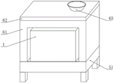
Screw air-cooled water chilling unit
Technical Field
The utility model relates to the technical field of screw type water chilling units, in particular to a screw type air cooling water chilling unit.
Background
The screw type water chilling unit is a water chilling unit which takes various screw compressors as a main machine and is an assembled refrigerating device consisting of a screw type refrigerating compressor, a condenser, an evaporator, a thermal expansion valve, an oil separator, an automatic control element, an instrument and the like.
However, the existing screw type water chilling unit generates a large amount of heat in use and inside, if the heat cannot be volatilized in time, two parts in the screw type water chilling unit are easily damaged, the service life of the screw type water chilling unit is shortened, and meanwhile, the screw type water chilling unit is heavy in self weight, so that the screw type water chilling unit is inconvenient to carry and move. Therefore, a screw type air-cooled water chilling unit is provided for solving the problems.
SUMMERY OF THE UTILITY MODEL
The utility model aims to provide a screw type air-cooled water chilling unit to solve the problems in the background technology.
In order to solve the technical problems, the utility model adopts the following technical scheme: the utility model provides a screw air-cooled cooling water set, which comprises an outer shell, the lower inner wall rigid coupling of shell has the condenser, the upper surface of condenser rigid coupling has oil separator and screw compressor respectively, and oil separator and screw compressor are linked together, the lower surface of shell is provided with removes the subassembly, it includes the base to remove the subassembly, the mounting groove has been seted up to the inside of base, the last inner wall rigid coupling of mounting groove has electric putter, electric putter's flexible end rigid coupling has the lifter plate, the equal rigid coupling of four corners of lifter plate lower surface has the support, the lower surface rigid coupling of support has the universal wheel, the lower surface rigid coupling of base has two fixed blocks, the spacing groove has been seted up to the inside of fixed block, the last inner wall of spacing groove is provided with the spring, the below of spring is provided with the limiting plate.
Preferably, the outside of shell is provided with radiator unit, and radiator unit includes the water tank, and the upper surface of water tank articulates there is the apron, and the feed inlet has been seted up to the upper surface of apron, and the inner wall rigid coupling has the immersible pump under one side of water tank, and the play water end rigid coupling of immersible pump has the water pipe, and first arc splint have been cup jointed in the surface activity of water pipe, and one side of first arc splint articulates there is second arc splint, and one side rigid coupling of water tank has the heat conduction stick.
Preferably, the upper surface of base and the lower surface looks rigid coupling of shell, and the equal rigid coupling in four corners of base lower surface has the supporting leg.
Preferably, the upper surface of the limiting plate is connected with the upper inner wall of the limiting groove through a spring.
Preferably, four sliding grooves are formed in the lower surface of the base, and the lower surface of the support penetrates through the inside of the sliding grooves and is located at the lower end of the base.
Preferably, one side of the heat conducting rod is fixedly connected with the outer surface of the shell.
Preferably, one side of the first arc-shaped clamping plate is fixedly connected with the inner wall of the water tank through the mounting block, and a bolt penetrates through the inner parts of one sides of the first arc-shaped clamping plate and the second arc-shaped clamping plate movably.
Compared with the prior art, the utility model has the beneficial effects that:
1. by arranging the moving assembly, when the shell needs to be moved in a short distance, the telescopic end of the electric push rod extends to drive the universal wheel to be lower than the position of the supporting leg, at the moment, the position of the shell can be easily moved, then, when the shell needs to be moved in a long distance, the shell can be moved by means of a forklift, when the forklift is used, a shovel of the forklift can be placed between two limiting plates in the limiting groove, at the moment, the position of the shovel of the forklift can be fixed by means of the acting force of the spring, and the shell is prevented from being deviated in the process of moving the shell, so that the shell is damaged;
2. through setting up radiator unit, can be with the help of the effort of heat conduction stick to the surface of heat transfer to the water tank on the shell, then through putting into ice-cube and water to the inside of water tank, and make the immersible pump begin to work simultaneously, drive the inside frozen water of water tank and carry out the circulation flow, can reduce the heat on water tank surface, the further heat that reduces the shell surface of being convenient for avoids the inside part of shell to overheat and damage.
Drawings
In order to more clearly illustrate the embodiments of the present invention or the technical solutions in the prior art, the drawings used in the description of the embodiments or the prior art will be briefly described below, it is obvious that the drawings in the following description are only some embodiments of the present invention, and for those skilled in the art, other drawings can be obtained according to the drawings without creative efforts.
FIG. 1 is a schematic view of the structure of the present invention.
Fig. 2 is a schematic view of the internal structure of the present invention.
FIG. 3 is a schematic view of a moving assembly according to the present invention;
fig. 4 is a schematic view of the installation structure of the first arc-shaped splint according to the present invention.
In the figure: 1. a housing; 2. a condenser; 3. an oil separator; 4. a screw compressor; 5. a moving assembly; 51. a base; 52. mounting grooves; 53. an electric push rod; 54. a lifting plate; 55. a support; 56. a universal wheel; 57. a fixed block; 58. a limiting groove; 59. a spring; 510. a limiting plate; 6. a heat dissipating component; 61. a water tank; 62. a cover plate; 63. a feed inlet; 64. a submersible pump; 65. a water pipe; 66. a first arc splint; 67. a second arc-shaped splint; 68. a heat conducting rod.
Detailed Description
The technical solutions in the embodiments of the present invention will be clearly and completely described below with reference to the drawings in the embodiments of the present invention, and it is obvious that the described embodiments are only a part of the embodiments of the present invention, and not all of the embodiments. All other embodiments, which can be derived by a person skilled in the art from the embodiments given herein without making any creative effort, shall fall within the protection scope of the present invention.
Example (b): as shown in fig. 1, 2 and 3, the present invention provides a screw air-cooled chiller, which comprises a housing 1, a condenser 2 is fixedly connected to the lower inner wall of the housing 1, an oil separator 3 and a screw compressor 4 are respectively fixedly connected to the upper surface of the condenser 2, the oil separator 3 is communicated with the screw compressor 4, a moving assembly 5 is arranged on the lower surface of the housing 1, the moving assembly 5 comprises a base 51, the upper surface of the base 51 is fixedly connected with the lower surface of the housing 1, supporting legs are fixedly connected to four corners of the lower surface of the base 51, an installation groove 52 is formed in the base 51, an electric push rod 53 is fixedly connected to the upper inner wall of the installation groove 52, a lifting plate 54 is fixedly connected to the telescopic end of the electric push rod 53, four corners of the lower surface of the lifting plate 54 are fixedly connected with supports 55, four sliding grooves are formed in the lower surface of the base 51, and the lower surface of the supports 55 penetrates through the inside of the sliding grooves and is located at the lower end of the base 51, the lower surface of the bracket 55 is fixedly connected with a universal wheel 56, the lower surface of the base 51 is fixedly connected with two fixed blocks 57, the inside of each fixed block 57 is provided with a limit groove 58, the upper inner wall of each limit groove 58 is provided with a spring 59, the lower part of each spring 59 is provided with a limit plate 510, the upper surfaces of the limit plates 510 are connected with the upper inner wall of each limit groove 58 through the springs 59, when the position of the shell 1 needs to be moved in a short distance, the telescopic end of the electric push rod 53 can be extended, when the telescopic end of the electric push rod 53 is extended, the lifting plate 54, the bracket 55 and the universal wheel 56 can be synchronously driven to descend, when the position of the universal wheel 56 is lower than the position of the supporting leg, the universal wheel 56 can be easily used for moving the position of the shell 1, when the shell 1 needs to be moved in a long distance, when the fork truck is used, the shovel of the fork truck can be placed between the two limit plates 510 in the limit grooves 58, under the effect of spring 59 can be convenient for fix the position of fork truck shovel, avoid the position of shell 1 to produce the skew and lead to the shell 1 to damage in the in-process that removes shell 1.
As shown in fig. 1, 2 and 4, further, a heat dissipation assembly 6 is disposed outside the housing 1, the heat dissipation assembly 6 includes a water tank 61, a cover plate 62 is hinged to an upper surface of the water tank 61, a feed inlet 63 is disposed on an upper surface of the cover plate 62, a submersible pump 64 is fixedly connected to a lower inner wall of one side of the water tank 61, a water pipe 65 is fixedly connected to a water outlet end of the submersible pump 64, a first arc clamp plate 66 is movably sleeved on a surface of the water pipe 65, a second arc clamp plate 67 is hinged to one side of the first arc clamp plate 66, one side of the first arc clamp plate 66 is fixedly connected to an inner wall of the water tank 61 through a mounting block, a bolt movably penetrates through an inner portion of one side of the first arc clamp plate 66 and the second arc clamp plate 67, a heat conduction rod 68 is fixedly connected to one side of the water tank 61, one side of the heat conduction rod 68 is fixedly connected to an outer surface of the housing 1, when the housing 1 emits a large amount of heat in use, the heat conduction rod 68 transfers the upper heat of the housing 1 to the surface of the water tank 61, at this time, ice and water can be put in from the cover plate 62, then the submersible pump 64 starts to work, when the submersible pump 64 works, the water is driven to circularly flow in the water pipe 65, the heat on the surface of the water tank 61 can be reduced through the continuous circular flow of the water, the heat on the surface of the shell 1 can be further reduced, and the damage of parts inside the shell 1 caused by overhigh temperature is avoided.
The working principle is as follows: when the shell 1 emits a large amount of heat in the using process, the heat conducting rod 68 transfers the upper heat of the shell 1 to the surface of the water tank 61, at this time, ice blocks and water can be put in from the cover plate 62, then the submersible pump 64 starts to work, when the submersible pump 64 works, water is driven to circularly flow in the water pipe 65, the heat on the surface of the water tank 61 can be reduced through the continuous circular flow of the water, the heat on the surface of the shell 1 can be further reduced, the damage of parts inside the shell 1 caused by overhigh temperature can be avoided, meanwhile, the position of the water pipe 65 can be fixed due to the arrangement of the first arc-shaped clamping plate 66 and the second arc-shaped clamping plate 67, the impact force can be prevented from causing the position movement of the water pipe 65 in the flowing process, meanwhile, the threaded connection of the first arc-shaped clamping plate 66 and the second arc-shaped clamping plate 67 is convenient for replacing the water pipe 65 at the later period, and then when the position of the shell 1 needs to be moved for a short distance, the telescopic end of the electric push rod 53 can be extended, and when the telescopic end of the electric push rod 53 is extended, the lifting plate 54, the bracket 55 and the universal wheel 56 are synchronously driven to lower, and when the position of the universal wheel 56 is lower than that of the supporting leg, the universal wheel 56 can be easily used to move the position of the shell 1, when the universal wheel is moved to the position, the telescopic end of the electric push rod 53 can be shortened again, the position of the universal wheel 56 is driven to be higher than the position of the supporting leg, the position of the housing 1 can be fixed, so that the universal wheels 56 are prevented from being damaged due to large-scale weight bearing for a long time, and when the housing 1 needs to be moved for a long distance, can be moved by a forklift, and when the forklift is used, the shovel of the forklift can be placed between the two limiting plates 510 in the limiting groove 58, under the effect of spring 59 can be convenient for fix the position of fork truck shovel, avoid the position of shell 1 to produce the skew and lead to the shell 1 to damage in the in-process that removes shell 1.
It will be apparent to those skilled in the art that various changes and modifications may be made in the present invention without departing from the spirit and scope of the utility model. Thus, if such modifications and variations of the present invention fall within the scope of the claims of the present invention and their equivalents, the present invention is also intended to include such modifications and variations.