CN215982170U - Lamp structure convenient to mount and dismount - Google Patents
Lamp structure convenient to mount and dismount Download PDFInfo
- Publication number
- CN215982170U CN215982170U CN202122051260.XU CN202122051260U CN215982170U CN 215982170 U CN215982170 U CN 215982170U CN 202122051260 U CN202122051260 U CN 202122051260U CN 215982170 U CN215982170 U CN 215982170U
- Authority
- CN
- China
- Prior art keywords
- lamp
- lamp body
- installation
- cover
- structure convenient
- Prior art date
- Legal status (The legal status is an assumption and is not a legal conclusion. Google has not performed a legal analysis and makes no representation as to the accuracy of the status listed.)
- Active
Links
Images
Landscapes
- Non-Portable Lighting Devices Or Systems Thereof (AREA)
Abstract
This technical scheme discloses lamps and lanterns structure convenient to installation is dismantled, include the lamp body and set up the lamp shade on the lamp body, lamp body and lamp shade both ends all are equipped with the side cap, and side cap one side is equipped with the flip that is used for installing the lamp body, and flip includes the buckle with side cap both sides swing joint, and buckle one end is through pivot and side cap opposite side fixed connection. This technical scheme has solved the problem that there is the part risk of losing in the push pedal formula mounting structure of line lamp among the prior art.
Description
Technical Field
This technical scheme relates to lamps and lanterns structure field, in particular to lamps and lanterns structure convenient to installation is dismantled.
Background
LED line lamp is LED wall washer series aluminium alloy lamp body promptly, and compact light and handy end cover and installing support are by the high-pressure die-casting high temperature resistant silicon rubber seal circle of aluminum alloy, guarantee waterproof reliability. The light fixtures may be installed singly or in multiple combinations. The LED lamp is suitable for local or contour illumination of various buildings, indoor and outdoor. The lamp shell is formed by drawing aluminum alloy, has bright lines, simple structure, attractive appearance, firmness, corrosion resistance and convenient installation. The lamp surface is subjected to electrostatic spraying treatment, and the high-temperature resistance and weather resistance are good. In the prior art, the lamp is installed by pushing the push plate open and then taking out the lampshade and using screws, and the push plate has loss risk in the process of disassembly and installation and is inconvenient for high-altitude operation. This technical scheme provides a lamps and lanterns structure convenient to installation is dismantled, adopts flip formula side cap fixed knot to construct, can solve present line lamp installation or dismantle easily lose the gadget and be not convenient for high altitude construction's problem, according to the side cap shape of difference, applicable in various line lamps.
Technical solution content
The present technical solution is directed to solve at least one of the technical problems in the related art to some extent. Therefore, the main purpose of the technical scheme is to provide a lamp structure convenient to mount and dismount, and the lamp structure aims to solve the problem that the push plate type mounting structure of the linear lamp in the prior art has the risk of losing parts.
In order to achieve the above object, the present technical solution provides a lamp structure convenient to mount and dismount, including a lamp body and a lamp shade arranged on the lamp body, side covers are arranged at both ends of the lamp body and the lamp shade, a flip cover for mounting the lamp body is arranged at one side of the side cover, the flip cover includes a buckle movably connected with both sides of the side cover, and one end of the buckle is fixedly connected with the other side of the side cover through a rotating shaft.
In one embodiment, the side cover is an integrally molded injection molded structure.
In one embodiment, the side cover lampshade and the two sides of the lamp body are connected in a clamping mode through the side covers.
In one embodiment, the flip cover is a one-piece cover structure.
In one embodiment, the lamp body and the lamp shade are connected by ultrasonic welding.
In one embodiment, the inner side of the side cover is provided with a shaft sleeve for matching with the rotating shaft.
In one embodiment, a screw hole for installing and fixing the lamp body is arranged below the flip cover.
The beneficial effects of this technical scheme are as follows:
the lamp structure convenient to mount and dismount provided by the technical scheme adopts the flip type side cover fixing structure, can solve the problems that small parts are easily lost and overhead operation is inconvenient to carry out during mounting or dismounting of the existing line lamp, and is applicable to various line lamps according to different side cover shapes.
Drawings
In order to more clearly illustrate the embodiments of the present invention or the technical solutions in the prior art, the drawings used in the description of the embodiments or the prior art will be briefly introduced below, it is obvious that the drawings in the following description are only some embodiments of the present invention, and for those skilled in the art, other drawings can be obtained according to the structures shown in the drawings without creative efforts.
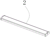
Fig. 1 is a schematic view of a lampshade in the technical scheme.
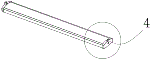
Fig. 2 is a schematic diagram of a setting position of the flip cover in the present technical solution.
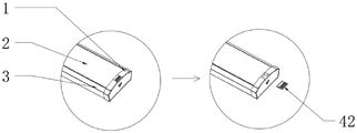
Fig. 3 is a schematic diagram of a push plate scheme adopted in the prior art in the technical scheme.
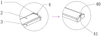
Fig. 4 is an enlarged schematic diagram of each component after the flip cover is adopted in the technical scheme.
[ list of reference numerals for main parts/components ]
| Reference numerals | Name (R) | Reference numerals | Name (R) |
| 1 | |
40 | |
| 2 | |
41 | |
| 3 | |
42 | |
| 4 | Flip cover |
Detailed Description
In order to make the purpose, technical solution and advantages of the present technical solution more clearly apparent, the technical solution in the embodiments of the present technical solution will be clearly and completely described below with reference to the drawings in the embodiments of the present technical solution. It is obvious that the described embodiments are only some, not all embodiments of the present solution.
All other embodiments obtained by a person skilled in the art based on the embodiments in the present technical solution without creative efforts belong to the protection scope of the present technical solution.
It should be noted that all the directional indicators (e.g., upper, lower, left, right, front, and rear … …) in the embodiment of the present invention are only used to explain the relative position relationship between the components, the movement condition, etc. in a specific state (as shown in the drawings), and if the specific posture is changed, the directional indicator is changed accordingly.
Descriptions in this technical solution as referring to "first", "second", etc. are only for descriptive purposes and are not to be interpreted as indicating or implying relative importance or implicitly indicating the number of technical features indicated. Thus, a feature defined as "first" or "second" may explicitly or implicitly include at least one such feature.
In the description of the present claims, "plurality" means at least two, e.g., two, three, etc., unless specifically limited otherwise.
In this technical solution, unless explicitly stated or limited otherwise, the terms "connected" and "fixed" should be understood broadly, for example, "fixed" may be a fixed connection, a detachable connection, or an integral formation; can be mechanically or electrically connected; they may be directly connected or indirectly connected through intervening media, or they may be connected internally or in any other suitable relationship, unless expressly stated otherwise. The specific meaning of the above terms in the present technical solution can be understood by those of ordinary skill in the art according to specific situations.
In addition, technical solutions between the embodiments in the present technical solution may be combined with each other, but it is necessary to be based on the realization of those skilled in the art, and when the technical solutions are contradictory or cannot be realized, such a combination of technical solutions should be considered to be absent, and is not within the protection scope claimed in the present technical solution.
Example 1:
referring to fig. 1 to 4, a lamp structure convenient to mount and dismount includes a lamp body 3 and a lampshade 2 arranged on the lamp body 3, side covers 1 are arranged at two ends of the lamp body 3 and the lampshade 2, a flip cover 4 for mounting the lamp body 3 is arranged on one side of the side cover 1, the flip cover 4 includes a buckle 40 movably connected with two sides of the side cover 1, and one end of the buckle 40 is fixedly connected with the other side of the side cover 1 through a rotating shaft 41.
Adopt 1 fixed knot of flip 4 formula side cap to construct, can solve present line lamp installation or dismantle and easily lose the problem of gadget and the high altitude construction of not being convenient for, according to 1 shape of side cap of difference, applicable in various line lamps. The structure of the utility model is different in that: the turnover structure is adopted, so that the small accessories are kept on the main body structure, the accessories are not lost in the dismounting process, and the high-altitude operation is convenient. The principle of the turnover is as follows: the round shafts at two sides of the flip cover 4 are arranged in the shaft sleeve of the side cover 1, the required angle turnover is realized through the limit of the side cover 1, and the disassembly and the installation are realized.
Referring to fig. 4, preferably, the side cover 1 is an integrally molded injection molded structure.
Referring to fig. 4, preferably, the side covers 1, the lamp housing 2 and the lamp body 3 are connected in a snap-fit manner at both sides through the side covers 1.
Referring to fig. 4, the folder 4 is preferably a one-piece cover structure.
Referring to fig. 4, preferably, the lamp body 3 and the lamp housing 2 are connected by ultrasonic welding.
Referring to fig. 4, preferably, a bushing for engaging the rotation shaft 41 is provided inside the side cover 1.
Referring to fig. 4, preferably, screw holes for mounting the fixed lamp body 3 are provided below the folder 4.
The working principle of the technical scheme is as follows:
1 fixed knot of flip 4 formula side cap constructs, can solve present line lamp installation or dismantle and easily lose the gadget and be not convenient for high altitude construction's problem, according to 1 shape of side cap of difference, applicable in various line lamps. The structure of the utility model is different in that: the turnover structure is adopted, so that the small accessories are kept on the main body structure, the accessories are not lost in the dismounting process, and the high-altitude operation is convenient. The principle of the turnover is as follows: the round shafts at two sides of the flip cover 4 are arranged in the shaft sleeve of the side cover 1, the required angle turnover is realized through the limit of the side cover 1, and the disassembly and the installation are realized.
The above description is only a preferred embodiment of the present disclosure, and not intended to limit the scope of the present disclosure, and all modifications and equivalents made by the contents of the specification and drawings of the present disclosure or directly/indirectly applied to other related technical fields are included in the scope of the present disclosure.
Claims (7)
1. The utility model provides a lamps and lanterns structure convenient to installation is dismantled, its characterized in that, include the lamp body and set up in lamp shade on the lamp body, the lamp body reaches the lamp shade both ends all are equipped with the side cap, side cap one side is equipped with the flip that is used for installing the lamp body, flip include with side cap both sides swing joint's buckle, buckle one end through the pivot with side cap opposite side fixed connection.
2. The light fixture structure of claim 1, wherein the side cover is an integrally molded plastic structure.
3. The lamp structure convenient for installation and disassembly of claim 1, wherein the side cover lampshade and the two sides of the lamp body are connected in a clamping manner through the side covers.
4. The light fixture structure convenient for installation and removal of claim 1, wherein the flip cover is a one-piece cover structure.
5. The lamp structure convenient for installation and disassembly as defined in claim 1, wherein the lamp body and the lampshade are connected by ultrasonic welding.
6. The lamp structure convenient for installation and disassembly as defined in claim 1, wherein a shaft sleeve for engaging with the rotating shaft is arranged inside the side cover.
7. The lamp structure convenient for assembly and disassembly as recited in claim 1, wherein a screw hole for fixing the lamp body is provided below the flip cover.
Priority Applications (1)
| Application Number | Priority Date | Filing Date | Title |
|---|---|---|---|
| CN202122051260.XU CN215982170U (en) | 2021-08-27 | 2021-08-27 | Lamp structure convenient to mount and dismount |
Applications Claiming Priority (1)
| Application Number | Priority Date | Filing Date | Title |
|---|---|---|---|
| CN202122051260.XU CN215982170U (en) | 2021-08-27 | 2021-08-27 | Lamp structure convenient to mount and dismount |
Publications (1)
| Publication Number | Publication Date |
|---|---|
| CN215982170U true CN215982170U (en) | 2022-03-08 |
Family
ID=80518775
Family Applications (1)
| Application Number | Title | Priority Date | Filing Date |
|---|---|---|---|
| CN202122051260.XU Active CN215982170U (en) | 2021-08-27 | 2021-08-27 | Lamp structure convenient to mount and dismount |
Country Status (1)
| Country | Link |
|---|---|
| CN (1) | CN215982170U (en) |
-
2021
- 2021-08-27 CN CN202122051260.XU patent/CN215982170U/en active Active
Similar Documents
| Publication | Publication Date | Title |
|---|---|---|
| CN213930557U (en) | High shed lamp | |
| CN113775984A (en) | Quick-connection structure and ceiling lamp | |
| CN201059479Y (en) | Light projector | |
| CN222230275U (en) | An LED bulb lamp that is easy to assemble | |
| CN211372124U (en) | A compact fan light | |
| CN219102732U (en) | A waterproof lamp | |
| CN221279348U (en) | Ceiling fan lamp support closing cap of buckle location | |
| CN222297774U (en) | Adjustable spotlight convenient to assemble | |
| CN224135827U (en) | High-luminous-efficiency direct-lighting structure purifying lamp | |
| CN224150881U (en) | Waterproof barrel spotlight | |
| CN206222031U (en) | A kind of easy-to-mount Lamp cup | |
| CN220249937U (en) | LED illuminating lamp string | |
| CN223020024U (en) | Ceiling lamp with luminous side part | |
| CN222122929U (en) | Street lamp structure | |
| CN214008993U (en) | Ceiling device and lamp assembly | |
| CN223020036U (en) | Low-cost post-mounting lamp holder structure | |
| CN222085962U (en) | A sealing structure of a wall washer lamp | |
| CN220082894U (en) | Headlight housing assembly | |
| CN210950968U (en) | A flip type integrated wire slot adjustable angle wall washer lamp | |
| CN221763382U (en) | Adjustable lamp structure | |
| CN223388473U (en) | LED lamp tube | |
| CN219063407U (en) | Novel waterproof projecting lamp | |
| CN221153297U (en) | Flashlight receiver and soft light recognition atmosphere lamp device | |
| CN216306279U (en) | Fan lamp with good heat dissipation effect | |
| CN212226813U (en) | An energy-saving spotlight with good waterproof performance |
Legal Events
| Date | Code | Title | Description |
|---|---|---|---|
| GR01 | Patent grant | ||
| GR01 | Patent grant |